2001 NISSAN ALMERA N16 P1690
[x] Cancel search: P1690Page 304 of 2493

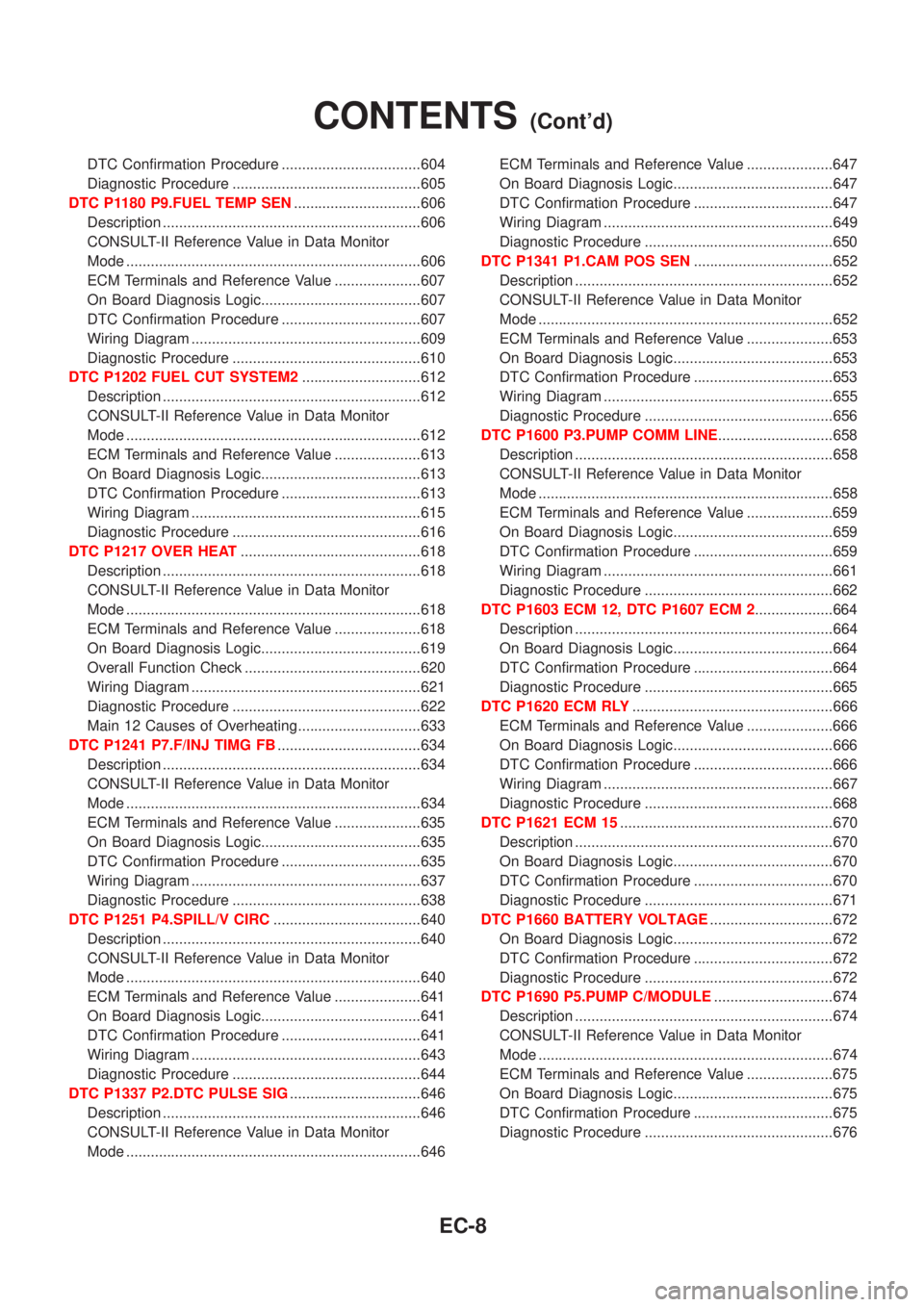
DTC Confirmation Procedure ..................................604
Diagnostic Procedure ..............................................605
DTC P1180 P9.FUEL TEMP SEN...............................606
Description ...............................................................606
CONSULT-II Reference Value in Data Monitor
Mode ........................................................................606
ECM Terminals and Reference Value .....................607
On Board Diagnosis Logic.......................................607
DTC Confirmation Procedure ..................................607
Wiring Diagram ........................................................609
Diagnostic Procedure ..............................................610
DTC P1202 FUEL CUT SYSTEM2.............................612
Description ...............................................................612
CONSULT-II Reference Value in Data Monitor
Mode ........................................................................612
ECM Terminals and Reference Value .....................613
On Board Diagnosis Logic.......................................613
DTC Confirmation Procedure ..................................613
Wiring Diagram ........................................................615
Diagnostic Procedure ..............................................616
DTC P1217 OVER HEAT............................................618
Description ...............................................................618
CONSULT-II Reference Value in Data Monitor
Mode ........................................................................618
ECM Terminals and Reference Value .....................618
On Board Diagnosis Logic.......................................619
Overall Function Check ...........................................620
Wiring Diagram ........................................................621
Diagnostic Procedure ..............................................622
Main 12 Causes of Overheating..............................633
DTC P1241 P7.F/INJ TIMG FB...................................634
Description ...............................................................634
CONSULT-II Reference Value in Data Monitor
Mode ........................................................................634
ECM Terminals and Reference Value .....................635
On Board Diagnosis Logic.......................................635
DTC Confirmation Procedure ..................................635
Wiring Diagram ........................................................637
Diagnostic Procedure ..............................................638
DTC P1251 P4.SPILL/V CIRC....................................640
Description ...............................................................640
CONSULT-II Reference Value in Data Monitor
Mode ........................................................................640
ECM Terminals and Reference Value .....................641
On Board Diagnosis Logic.......................................641
DTC Confirmation Procedure ..................................641
Wiring Diagram ........................................................643
Diagnostic Procedure ..............................................644
DTC P1337 P2.DTC PULSE SIG................................646
Description ...............................................................646
CONSULT-II Reference Value in Data Monitor
Mode ........................................................................646ECM Terminals and Reference Value .....................647
On Board Diagnosis Logic.......................................647
DTC Confirmation Procedure ..................................647
Wiring Diagram ........................................................649
Diagnostic Procedure ..............................................650
DTC P1341 P1.CAM POS SEN..................................652
Description ...............................................................652
CONSULT-II Reference Value in Data Monitor
Mode ........................................................................652
ECM Terminals and Reference Value .....................653
On Board Diagnosis Logic.......................................653
DTC Confirmation Procedure ..................................653
Wiring Diagram ........................................................655
Diagnostic Procedure ..............................................656
DTC P1600 P3.PUMP COMM LINE............................658
Description ...............................................................658
CONSULT-II Reference Value in Data Monitor
Mode ........................................................................658
ECM Terminals and Reference Value .....................659
On Board Diagnosis Logic.......................................659
DTC Confirmation Procedure ..................................659
Wiring Diagram ........................................................661
Diagnostic Procedure ..............................................662
DTC P1603 ECM 12, DTC P1607 ECM 2...................664
Description ...............................................................664
On Board Diagnosis Logic.......................................664
DTC Confirmation Procedure ..................................664
Diagnostic Procedure ..............................................665
DTC P1620 ECM RLY.................................................666
ECM Terminals and Reference Value .....................666
On Board Diagnosis Logic.......................................666
DTC Confirmation Procedure ..................................666
Wiring Diagram ........................................................667
Diagnostic Procedure ..............................................668
DTC P1621 ECM 15....................................................670
Description ...............................................................670
On Board Diagnosis Logic.......................................670
DTC Confirmation Procedure ..................................670
Diagnostic Procedure ..............................................671
DTC P1660 BATTERY VOLTAGE..............................672
On Board Diagnosis Logic.......................................672
DTC Confirmation Procedure ..................................672
Diagnostic Procedure ..............................................672
DTC P1690 P5.PUMP C/MODULE.............................674
Description ...............................................................674
CONSULT-II Reference Value in Data Monitor
Mode ........................................................................674
ECM Terminals and Reference Value .....................675
On Board Diagnosis Logic.......................................675
DTC Confirmation Procedure ..................................675
Diagnostic Procedure ..............................................676
CONTENTS(Cont'd)
EC-8
Page 788 of 2493

Alphabetical & P No. Index for DTCNJEC0600ALPHABETICAL INDEX FOR DTCNJEC0600S01X: Applicable Ð: Not applicable
Items
(CONSULT-II screen terms)DTC
MI illumination Reference page
CONSULT-II ECM
ACCEL POS SENSOR P0120 0403 X EC-577
BATTERY VOLTAGE P1660 0502 Ð EC-672
BRAKE SW P0571 0807 X EC-597
COOLANT TEMP SEN P0115 0103 X EC-572
CRANK POS SEN (TDC) P0335 0407 X EC-587
ECM RLY P1620 0902 X EC-666
ECM 2 P1607 0301 X EC-664
ECM 10 P1107 0802 X EC-604
ECM 12 P1603 0901 X EC-664
ECM 15 P1621 0903 Ð EC-670
FUEL CUT SYSTEM2 P1202 1002 X EC-612
MASS AIR FLOW SEN P0100 0102 X EC-566
NO DTC IS DETECTED.
FURTHER TESTING
MAY BE REQUIRED.P0000 0505ÐÐ
OVER HEAT P1217 0208 X EC-618
P1´CAM POS SEN P1341 0701 X EC-652
P2´TDC PULSE SIG P1337 0702 X EC-646
P3´PUMP COMM LINE P1600 0703 X EC-658
P4´SPILL/V CIRC P1251 0704 X EC-640
P5´PUMP C/MODULE P1690 0705 X EC-674
P7´F/INJ TIMG FB P1241 0707 X EC-634
P9´FUEL TEMP SEN P1180 0402 X EC-606
VEHICLE SPEED SEN P0500 0104 X EC-593
TROUBLE DIAGNOSIS Ð INDEXYD
Alphabetical & P No. Index for DTC
EC-492
Page 789 of 2493

P NO. INDEX FOR DTC=NJEC0600S02X: Applicable Ð: Not applicable
DTC
MI illuminationItems
(CONSULT-II screen terms)Reference page
CONSULT-II ECM
P0000 0505ÐNO DTC IS DETECTED.
FURTHER TESTING
MAY BE REQUIRED.Ð
P0100 0102 X MASS AIR FLOW SEN EC-566
P0115 0103 X COOLANT TEMP SEN EC-572
P0120 0403 X ACCEL POS SENSOR EC-577
P0335 0407 X CRANK POS SEN (TDC) EC-587
P0500 0104 X VEHICLE SPEED SEN EC-593
P0571 0807 X BRAKE SW EC-597
P1107 0802 X ECM 10 EC-604
P1180 0402 X P9´FUEL TEMP SEN EC-606
P1202 1002 X FUEL CUT SYSTEM2 EC-612
P1217 0208 X OVER HEAT EC-618
P1241 0707 X P7´F/INJ TIMG FB EC-634
P1251 0704 X P4´SPILL/V CIRC EC-640
P1337 0702 X P2´TDC PULSE SIG EC-646
P1341 0701 X P1´CAM POS SEN EC-652
P1600 0703 X P3´PUMP COMM LINE EC-658
P1603 0901 X ECM 12 EC-664
P1607 0301 X ECM 2 EC-664
P1620 0902 X ECM RLY EC-666
P1621 0903 Ð ECM 15 EC-670
P1660 0502 Ð BATTERY VOLTAGE EC-672
P1690 0705 X P5´PUMP C/MODULE EC-674
TROUBLE DIAGNOSIS Ð INDEXYD
Alphabetical & P No. Index for DTC (Cont'd)
EC-493
Page 970 of 2493

SEF437Y
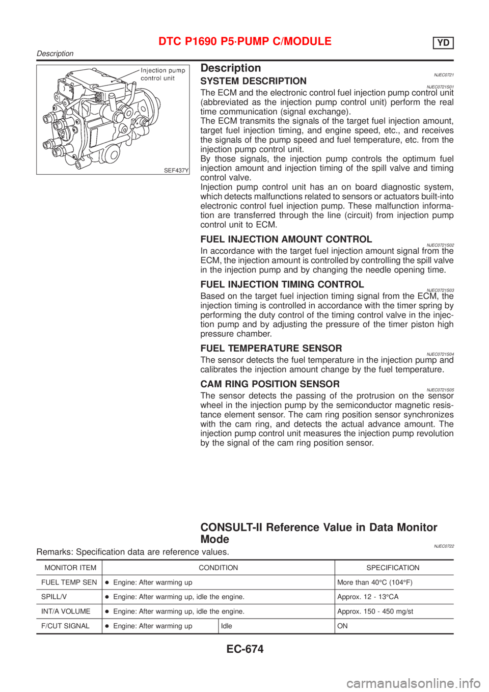
DescriptionNJEC0721SYSTEM DESCRIPTIONNJEC0721S01The ECM and the electronic control fuel injection pump control unit
(abbreviated as the injection pump control unit) perform the real
time communication (signal exchange).
The ECM transmits the signals of the target fuel injection amount,
target fuel injection timing, and engine speed, etc., and receives
the signals of the pump speed and fuel temperature, etc. from the
injection pump control unit.
By those signals, the injection pump controls the optimum fuel
injection amount and injection timing of the spill valve and timing
control valve.
Injection pump control unit has an on board diagnostic system,
which detects malfunctions related to sensors or actuators built-into
electronic control fuel injection pump. These malfunction informa-
tion are transferred through the line (circuit) from injection pump
control unit to ECM.
FUEL INJECTION AMOUNT CONTROLNJEC0721S02In accordance with the target fuel injection amount signal from the
ECM, the injection amount is controlled by controlling the spill valve
in the injection pump and by changing the needle opening time.
FUEL INJECTION TIMING CONTROLNJEC0721S03Based on the target fuel injection timing signal from the ECM, the
injection timing is controlled in accordance with the timer spring by
performing the duty control of the timing control valve in the injec-
tion pump and by adjusting the pressure of the timer piston high
pressure chamber.
FUEL TEMPERATURE SENSORNJEC0721S04The sensor detects the fuel temperature in the injection pump and
calibrates the injection amount change by the fuel temperature.
CAM RING POSITION SENSORNJEC0721S05The sensor detects the passing of the protrusion on the sensor
wheel in the injection pump by the semiconductor magnetic resis-
tance element sensor. The cam ring position sensor synchronizes
with the cam ring, and detects the actual advance amount. The
injection pump control unit measures the injection pump revolution
by the signal of the cam ring position sensor.
CONSULT-II Reference Value in Data Monitor
Mode
NJEC0722Remarks: Specification data are reference values.
MONITOR ITEM CONDITION SPECIFICATION
FUEL TEMP SEN+Engine: After warming up More than 40ÉC (104ÉF)
SPILL/V+Engine: After warming up, idle the engine. Approx. 12 - 13ÉCA
INT/A VOLUME+Engine: After warming up, idle the engine. Approx. 150 - 450 mg/st
F/CUT SIGNAL+Engine: After warming up Idle ON
DTC P1690 P5´PUMP C/MODULEYD
Description
EC-674
Page 971 of 2493

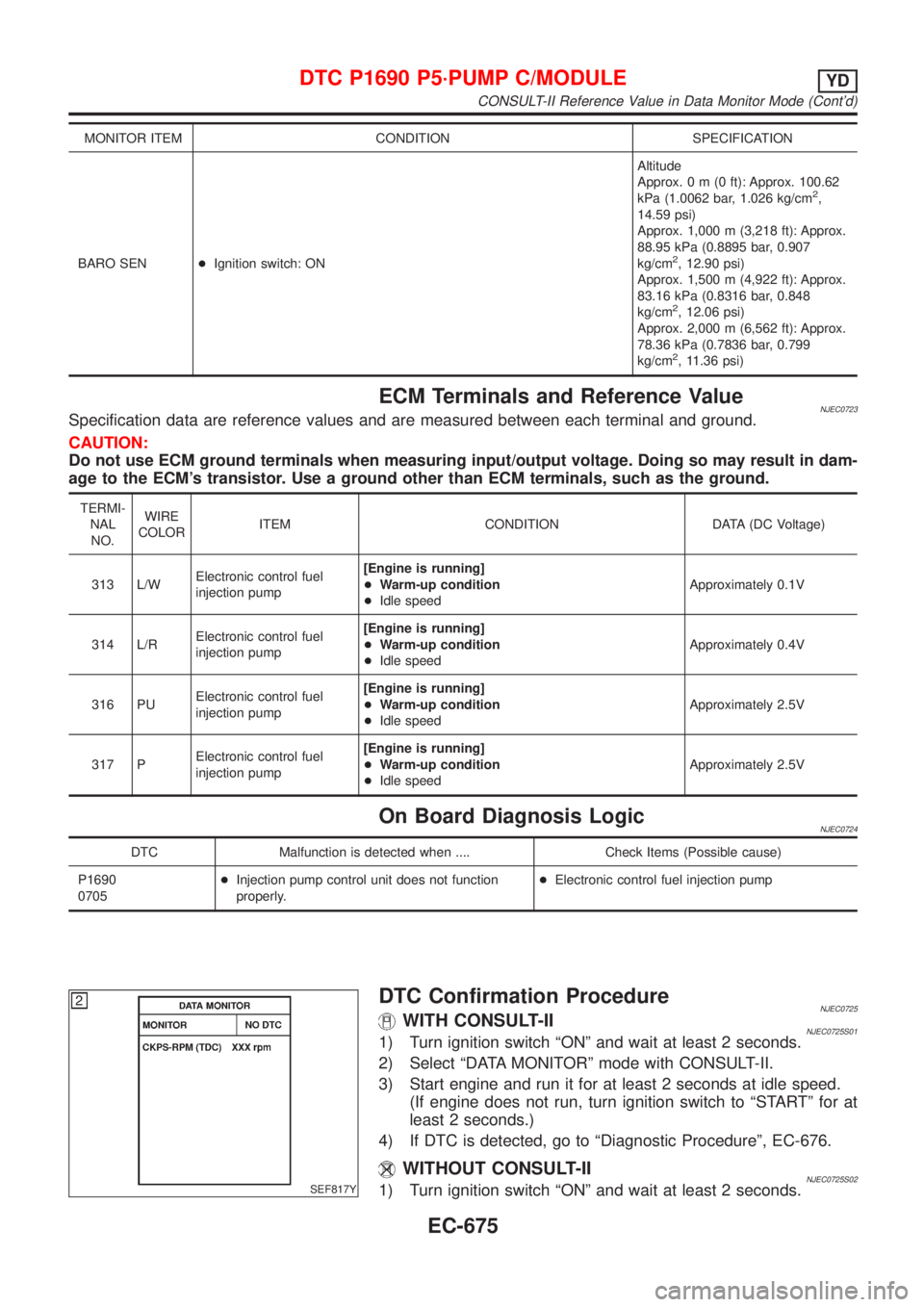
MONITOR ITEM CONDITION SPECIFICATION
BARO SEN+Ignition switch: ONAltitude
Approx.0m(0ft): Approx. 100.62
kPa (1.0062 bar, 1.026 kg/cm
2,
14.59 psi)
Approx. 1,000 m (3,218 ft): Approx.
88.95 kPa (0.8895 bar, 0.907
kg/cm
2, 12.90 psi)
Approx. 1,500 m (4,922 ft): Approx.
83.16 kPa (0.8316 bar, 0.848
kg/cm
2, 12.06 psi)
Approx. 2,000 m (6,562 ft): Approx.
78.36 kPa (0.7836 bar, 0.799
kg/cm
2, 11.36 psi)
ECM Terminals and Reference ValueNJEC0723Specification data are reference values and are measured between each terminal and ground.
CAUTION:
Do not use ECM ground terminals when measuring input/output voltage. Doing so may result in dam-
age to the ECM's transistor. Use a ground other than ECM terminals, such as the ground.
TERMI-
NAL
NO.WIRE
COLORITEM CONDITION DATA (DC Voltage)
313 L/WElectronic control fuel
injection pump[Engine is running]
+Warm-up condition
+Idle speedApproximately 0.1V
314 L/RElectronic control fuel
injection pump[Engine is running]
+Warm-up condition
+Idle speedApproximately 0.4V
316 PUElectronic control fuel
injection pump[Engine is running]
+Warm-up condition
+Idle speedApproximately 2.5V
317 PElectronic control fuel
injection pump[Engine is running]
+Warm-up condition
+Idle speedApproximately 2.5V
On Board Diagnosis LogicNJEC0724
DTC Malfunction is detected when .... Check Items (Possible cause)
P1690
0705+Injection pump control unit does not function
properly.+Electronic control fuel injection pump
SEF817Y
DTC Confirmation ProcedureNJEC0725WITH CONSULT-IINJEC0725S011) Turn ignition switch ªONº and wait at least 2 seconds.
2) Select ªDATA MONITORº mode with CONSULT-II.
3) Start engine and run it for at least 2 seconds at idle speed.
(If engine does not run, turn ignition switch to ªSTARTº for at
least 2 seconds.)
4) If DTC is detected, go to ªDiagnostic Procedureº, EC-676.
WITHOUT CONSULT-IINJEC0725S021) Turn ignition switch ªONº and wait at least 2 seconds.
DTC P1690 P5´PUMP C/MODULEYD
CONSULT-II Reference Value in Data Monitor Mode (Cont'd)
EC-675
Page 972 of 2493

2) Start engine and run it for at least 2 seconds at idle speed.
(If engine does not run, turn ignition switch to ªSTARTº for at
least 2 seconds.)
3) Turn ignition switch ªOFFº, wait at least 5 seconds and then
turn ªONº.
4) Perform ªDiagnostic Test Mode II (Self-diagnostic results)º with
ECM.
5) If DTC is detected, go to ªDiagnostic Procedureº, EC-676.
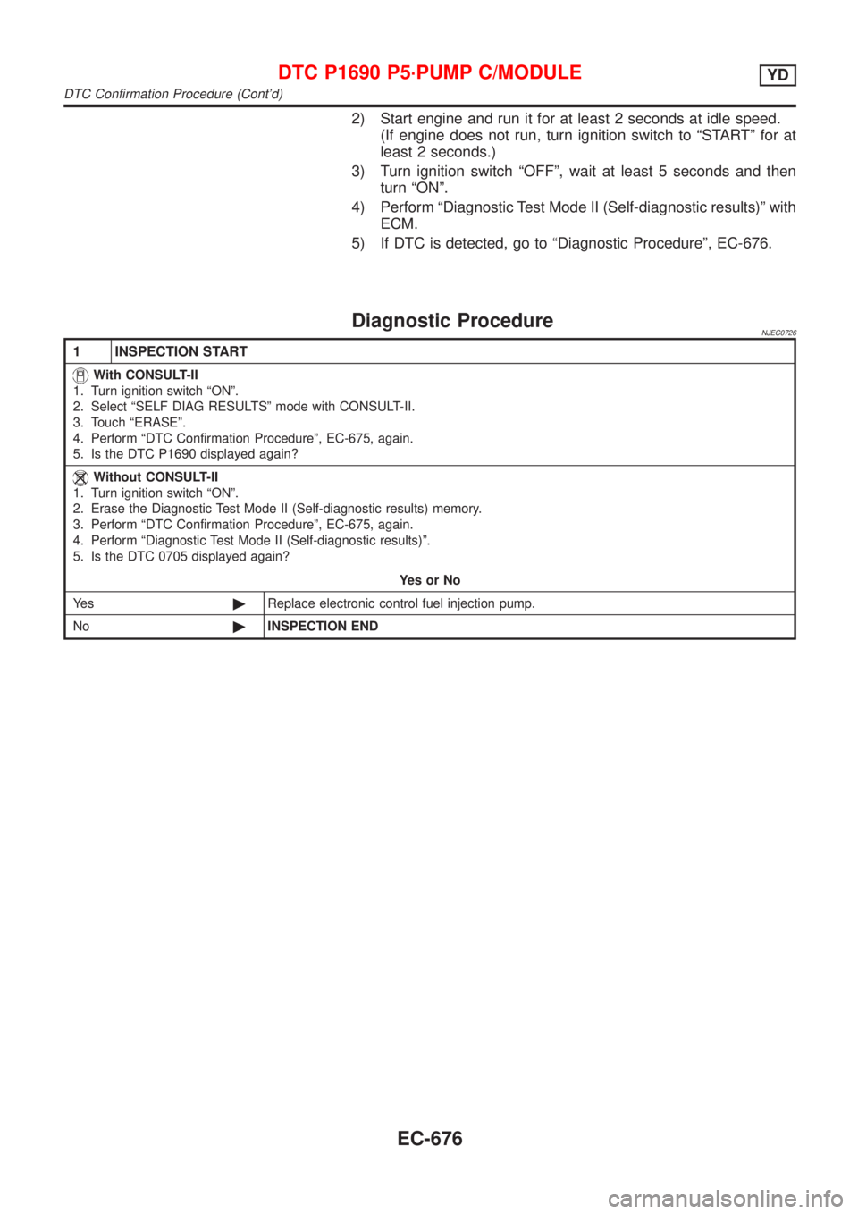
Diagnostic ProcedureNJEC0726
1 INSPECTION START
With CONSULT-II
1. Turn ignition switch ªONº.
2. Select ªSELF DIAG RESULTSº mode with CONSULT-II.
3. Touch ªERASEº.
4. Perform ªDTC Confirmation Procedureº, EC-675, again.
5. Is the DTC P1690 displayed again?
Without CONSULT-II
1. Turn ignition switch ªONº.
2. Erase the Diagnostic Test Mode II (Self-diagnostic results) memory.
3. Perform ªDTC Confirmation Procedureº, EC-675, again.
4. Perform ªDiagnostic Test Mode II (Self-diagnostic results)º.
5. Is the DTC 0705 displayed again?
YesorNo
Ye s©Replace electronic control fuel injection pump.
No©INSPECTION END
DTC P1690 P5´PUMP C/MODULEYD
DTC Confirmation Procedure (Cont'd)
EC-676