2001 NISSAN ALMERA N16 radiator
[x] Cancel search: radiatorPage 7 of 2493

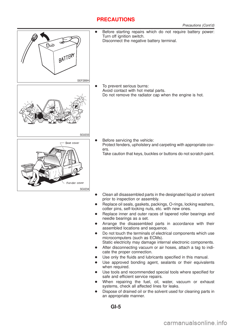
SEF289H
+Before starting repairs which do not require battery power:
Turn off ignition switch.
Disconnect the negative battery terminal.
SGI233
+To prevent serious burns:
Avoid contact with hot metal parts.
Do not remove the radiator cap when the engine is hot.
SGI234
+Before servicing the vehicle:
Protect fenders, upholstery and carpeting with appropriate cov-
ers.
Take caution that keys, buckles or buttons do not scratch paint.
+Clean all disassembled parts in the designated liquid or solvent
prior to inspection or assembly.
+Replace oil seals, gaskets, packings, O-rings, locking washers,
cotter pins, self-locking nuts, etc. with new ones.
+Replace inner and outer races of tapered roller bearings and
needle bearings as a set.
+Arrange the disassembled parts in accordance with their
assembled locations and sequence.
+Do not touch the terminals of electrical components which use
microcomputers (such as ECMs).
Static electricity may damage internal electronic components.
+After disconnecting vacuum or air hoses, attach a tag to indi-
cate the proper connection.
+Use only the fluids and lubricants specified in this manual.
+Use approved bonding agent, sealants or their equivalents
when required.
+Use tools and recommended special tools where specified for
safe and efficient service repairs.
+When repairing the fuel, oil, water, vacuum or exhaust
systems, check all affected lines for leaks.
+Dispose of drained oil or the solvent used for cleaning parts in
an appropriate manner.
PRECAUTIONS
Precautions (Cont'd)
GI-5
Page 58 of 2493

NJMA0036
Shown below are Pre-delivery Inspection Items required for the new vehicle. It is recommended that
necessary items other than those listed here be added, paying due regard to the conditions in each
country.
Perform applicable items on each model. Consult text of this section for specifications.
UNDER HOOD Ð engine off
Radiator coolant level and coolant hose connections for leaks
Battery fluid level, specific gravity and conditions of battery terminals
Drive belts tension
Fuel filter for water or dusts (Diesel only), and fuel lines and connections for leaks
Engine oil level and oil leaks
Clutch and brake reservoir fluid level and fluid lines for leaks
Windshield and rear window washer and headlamp cleaner reservoir fluid level
Power steering reservoir fluid level and hose connections for leaks
ON INSIDE AND OUTSIDE
Remove front spring/strut spacer (If applicable)
Operation of all instruments, gauges, lights and accessories
Operation of horn(s), wiper and washer
Steering lock for operation
Check air conditioner for gas leaks
Front and rear seats, and seat belts for operation
All moldings, trims and fittings for fit and alignment
All windows for operation and alignment
Hood, trunk lid, door panels for fit and alignment
Latches, keys and locks for operation
Weatherstrips for adhesion and fit
Headlamp aiming
Tighten wheel nuts (Inc. inner nuts if applicable)
Tire pressure (Inc. spare tire)
Check front wheels for toe-in
Install clock/voltmeter/room lamp fuse (If applicable)
Install deodorizing filter to air conditioner (If applicable)
Remove wiper blade protectors (If applicable)
UNDER BODY
Manual transmission/transaxle, transfer and differential gear oil level
Brake and fuel lines and oil/fluid reservoirs for leaks
Tighten bolts and nuts of steering linkage and gear box, suspension, propeller shafts and drive shafts
Tighten rear body bolts and nuts (Models with wooden bed only)
ROAD TEST
Clutch operation
Parking brake operation
Service brake operation
Automatic transmission/transaxle shift timing and kickdown
Steering control and returnability
Engine performance
Squeaks and rattles
ENGINE OPERATING AND HOT
Adjust idle speed
Automatic transmission/transaxle fluid level
Engine idling and stop knob operation (Diesel only)
FINAL INSPECTION
Install necessary parts (outside mirror, wheel covers, seat belts, mat, carpet or mud flaps)
Inspect for interior and exterior metal and paint damage
Check for spare tire, jack, tools (wheel chock), and literature
Wash, clean interior and exterior
: Not applicable to this model
PRE-DELIVERY INSPECTION ITEMS
MA-2
Page 78 of 2493

SMA089D
Engine Coolant Mixture Ratio=NJMA0006S03The engine cooling system is filled at the factory with a high-quality,
year-round and extended life engine coolant. The high quality
engine coolant contains the specific solutions effective for the anti-
corrosion and the anti-freeze function. Therefore, additional cool-
ing system additives are not necessary.
CAUTION:
+For Europe
When adding or replacing coolant, be sure to use only
Genuine NISSAN Anti-freeze Coolant (L2N) or equivalent.
Because L2N is premixed type coolant.
+Except for Europe
When adding or replacing coolant, be sure to use only a
Nissan Genuine Engine Coolant or equivalent in its qual-
ity with the proper mixture ratio. See the examples shown
left.
The use of other types of engine coolant may damage your
cooling system.
+When checking the engine coolant mixture ratio by the coolant
hydrometer, use the chart below to correct your hydrometer
reading (specific gravity) according to coolant temperature.
Mixed coolant specific gravity
Unit: specific gravity
Engine coolant mixture
ratioCoolant temperature ÉC (ÉF)
15 (59) 25 (77) 35 (95) 45 (113)
30% 1.046 - 1.050 1.042 - 1.046 1.038 - 1.042 1.033 - 1.038
50% 1.076 - 1.080 1.070 - 1.076 1.065 - 1.071 1.059 - 1.065
WARNING:
Never remove the radiator cap when the engine is hot. Serious
burns could be caused by high pressure fluid escaping from
the radiator. Wait until the engine and radiator cool down.
RECOMMENDED FLUIDS AND LUBRICANTS
Engine Coolant Mixture Ratio
MA-22
Page 101 of 2493

CAUTION:
+After removing timing chain, do not turn crankshaft and
camshaft separately, or valves will strike piston heads.
+When installing chain tensioner, oil seats, or other sliding
parts, lubricate contacting surfaces with new engine oil.
+Apply new engine oil to bolt threads and seat surfaces
when installing camshaft sprocket and crankshaft pulley.
+When removing oil pump assembly, remove camshaft
position sensor (PHASE), then remove timing chain from
engine.
+Be careful not to damage sensor edges.
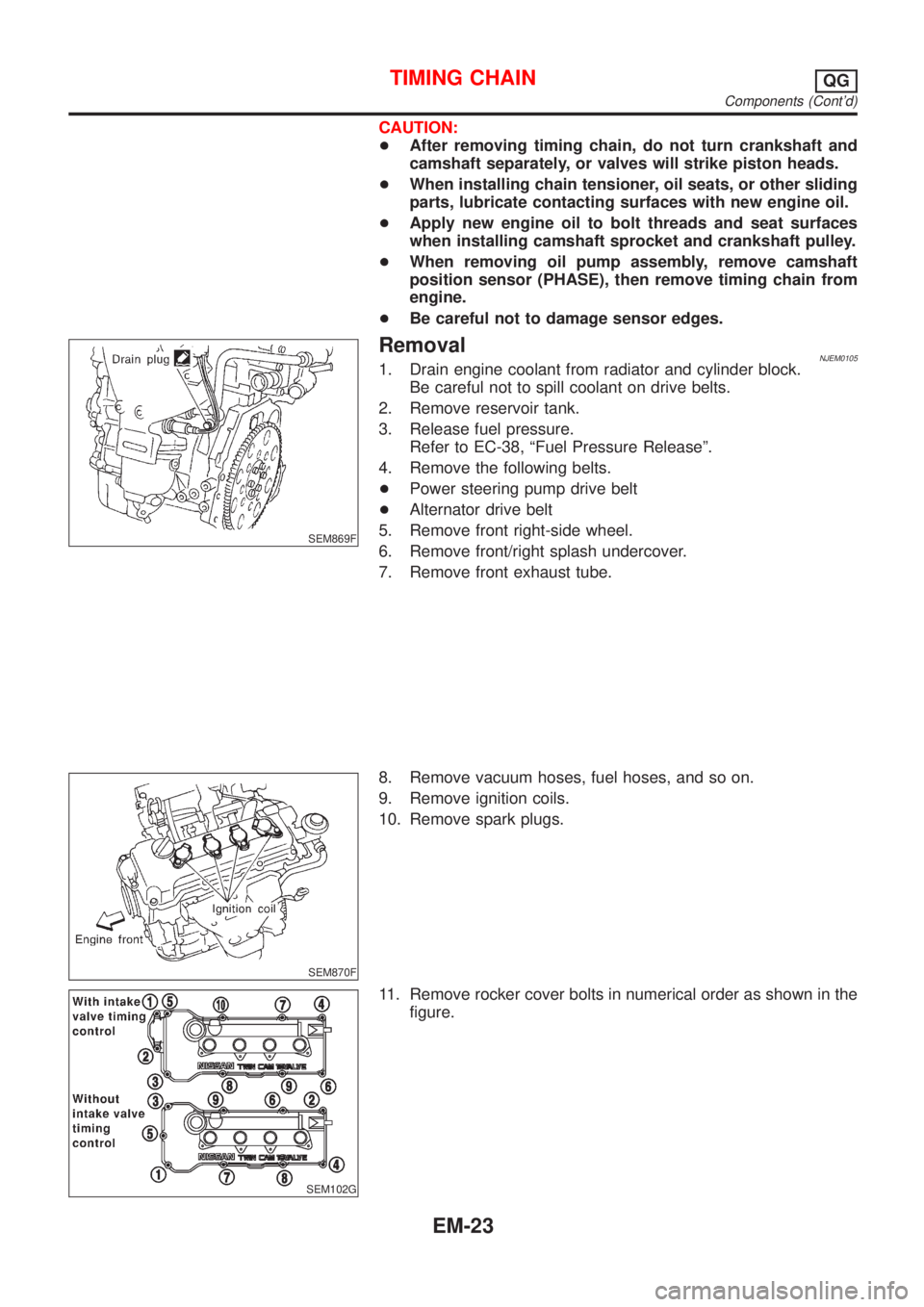
SEM869F
RemovalNJEM01051. Drain engine coolant from radiator and cylinder block.
Be careful not to spill coolant on drive belts.
2. Remove reservoir tank.
3. Release fuel pressure.
Refer to EC-38, ªFuel Pressure Releaseº.
4. Remove the following belts.
+Power steering pump drive belt
+Alternator drive belt
5. Remove front right-side wheel.
6. Remove front/right splash undercover.
7. Remove front exhaust tube.
SEM870F
8. Remove vacuum hoses, fuel hoses, and so on.
9. Remove ignition coils.
10. Remove spark plugs.
SEM102G
11. Remove rocker cover bolts in numerical order as shown in the
figure.
TIMING CHAINQG
Components (Cont'd)
EM-23
Page 112 of 2493

CAUTION:
+When installing camshaft and oil seal, lubricate contacting
surfaces with new engine oil.
+When tightening cylinder head bolts, camshaft sprocket
bolts and camshaft bracket bolts, lubricate bolt threads
and seat surfaces with new engine oil.
+Attach tags to valve lifters so as not to mix them up.
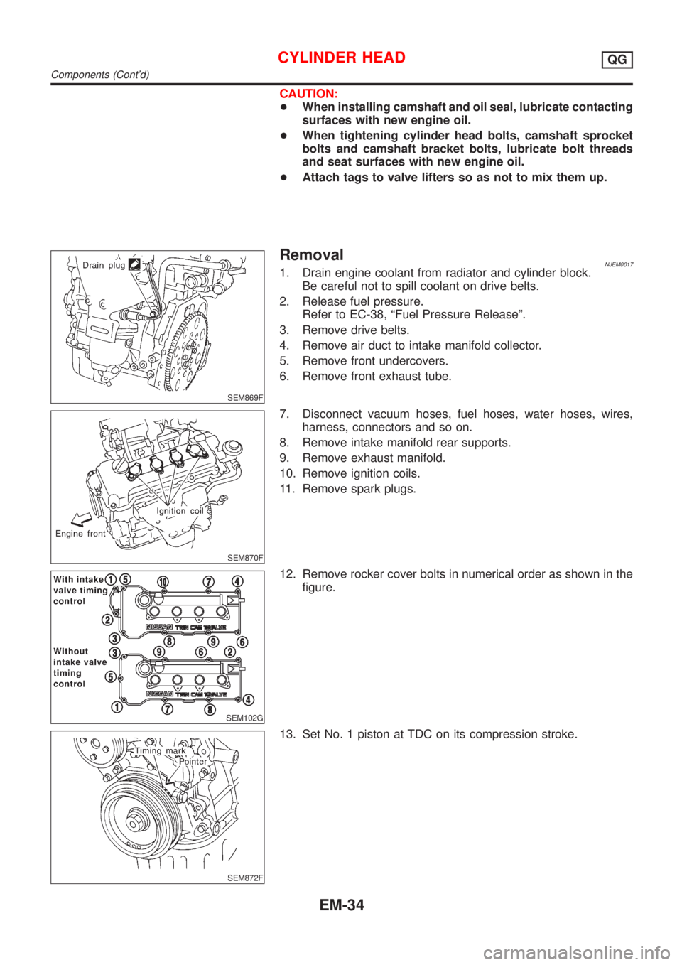
SEM869F
RemovalNJEM00171. Drain engine coolant from radiator and cylinder block.
Be careful not to spill coolant on drive belts.
2. Release fuel pressure.
Refer to EC-38, ªFuel Pressure Releaseº.
3. Remove drive belts.
4. Remove air duct to intake manifold collector.
5. Remove front undercovers.
6. Remove front exhaust tube.
SEM870F
7. Disconnect vacuum hoses, fuel hoses, water hoses, wires,
harness, connectors and so on.
8. Remove intake manifold rear supports.
9. Remove exhaust manifold.
10. Remove ignition coils.
11. Remove spark plugs.
SEM102G
12. Remove rocker cover bolts in numerical order as shown in the
figure.
SEM872F
13. Set No. 1 piston at TDC on its compression stroke.
CYLINDER HEADQG
Components (Cont'd)
EM-34
Page 128 of 2493

WARNING:
+Position vehicle on a flat and solid surface.
+Place chocks at front and back of rear wheels.
+Do not remove engine until exhaust system has com-
pletely cooled off, otherwise, you may burn yourself
and/or fire may break out in fuel line.
+Before disconnecting fuel hose, release pressure.
Refer to EC-38, ªFuel Pressure Releaseº.
+Be sure to lift engine and transaxle in a safe manner.
+For engines not equipped with engine slingers, attach
proper slingers and bolts described in PARTS CATALOG.
CAUTION:
+When lifting engine, be sure to clear surrounding parts.
Use special care near accelerator wire casing, brake lines
and brake master cylinder.
+When lifting the engine, always use engine slingers in a
safe manner.
+When removing drive shaft, be careful not to damage
grease seal of transaxle.
+Before separating engine and transaxle, remove crank-
shaft position sensor (POS) from the cylinder block
assembly.
+Always be extra careful not to damage edge of crankshaft
position sensor (POS), or signal plate teeth.
Engine cannot be removed separately from transaxle. Remove
engine with transaxle as an assembly.
REMOVALNJEM0022S011. Drain coolant from radiator and cylinder block. Refer to LC-17,
ªChanging Engine Coolantº.
2. Remove coolant reservoir tank and bracket.
3. Drain engine oil.
4. Remove battery and battery tray.
5. Remove air cleaner and air duct.
6. Remove drive belts.
7. Remove alternator and air conditioner compressor from
engine.
8. Remove power steering oil pump from engine and position
aside.
Power steering oil pump does not need to be disconnected
from power steering tubes.
ENGINE ASSEMBLYQG
Removal and Installation (Cont'd)
EM-50
Page 129 of 2493

SEM174D
9. Remove the following parts:
+RH and LH front tires
+Splash covers
+RH and LH brake caliper assemblies
Refer to BR-27, ªFRONT DISC BRAKEº.
Brake hose does not need to be disconnected from brake
caliper assembly. Never depress brake pedal.
+RH & LH drive shaft. Refer to AX-10, ªDrive Shaftº.
When removing drive shaft, be careful not to damage tran-
saxle side grease seal.
SEM109G
+Disconnect control rod and support rod from transaxle. (M/T
models.)
Refer to MT-29, ªTRANSAXLE GEAR CONTROLº.
+Disconnect control cable from transaxle. (A/T models.)
Refer to AT-346, ªRemovalº.
SEM108G
+Center member
+Front exhaust tube
+Stabilizer bar
+Cooling fan
+Radiator
+Disconnect wires, harness, pipes, hoses and so on.
10. Lift up engine slightly and disconnect or remove all engine
mountings.
When lifting engine, be sure to clear surrounding parts. Use
special care near brake tubes and brake master cylinder.
11. Remove engine with transaxle as shown.
SEM420D
INSTALLATIONNJEM0022S02+Install in reverse order of removal.
ENGINE ASSEMBLYQG
Removal and Installation (Cont'd)
EM-51
Page 187 of 2493

Removal and InstallationNJEM0101
JEM264G
PREPARATIVE WORKNJEM0101S01Remove the following parts.
+Under cover
+Engine coolant (drain)
Refer to LC-43, ªChanging Engine Coolantº.
+Radiator upper hose
+Cooling fan
Refer to LC-42, ªRadiatorº.
+Radiator mount bracket
+Water inlet pipe
+Exhaust front tube (disconnect)
Refer to FE-27, ªRemoval and Installationº, ªEXHAUST SYS-
TEMº.
CATALYSTNJEM0101S02RemovalNJEM0101S0201+Remove the catalyst, refer to above illustration.
CAUTION:
Do not disassemble.
InstallationNJEM0101S0202Install two locking pins into both sides of the catalytic converter. Be
careful not to confuse locking pins with insulator mounting bolts.
Catalytic converter locking pin:
Flange bolt (black)
Insulator mounting bolt:
Washer bolt (silver or yellow)
CATALYSTYD
Removal and Installation
EM-109