2001 NISSAN ALMERA N16 radiator
[x] Cancel search: radiatorPage 1697 of 2493

Service Data and Specifications (SDS)
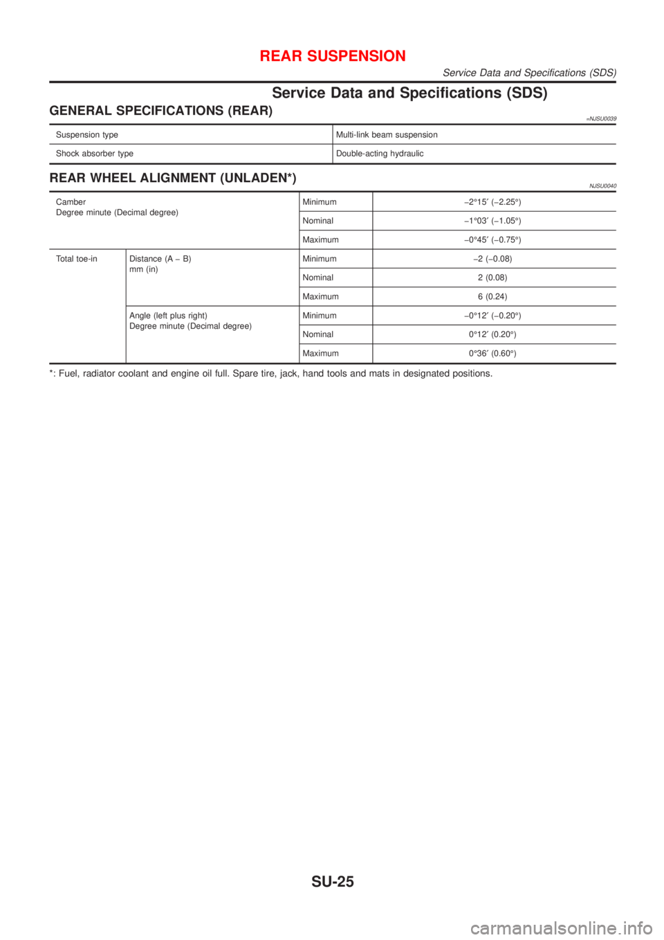
GENERAL SPECIFICATIONS (REAR)=NJSU0039
Suspension type Multi-link beam suspension
Shock absorber type Double-acting hydraulic
REAR WHEEL ALIGNMENT (UNLADEN*)NJSU0040
Camber
Degree minute (Decimal degree)Minimum þ2É15¢(þ2.25É)
Nominal þ1É03¢(þ1.05É)
Maximum þ0É45¢(þ0.75É)
Total toe-in Distance (A þ B)
mm (in)Minimum þ2 (þ0.08)
Nominal 2 (0.08)
Maximum 6 (0.24)
Angle (left plus right)
Degree minute (Decimal degree)Minimum þ0É12¢(þ0.20É)
Nominal 0É12¢(0.20É)
Maximum 0É36¢(0.60É)
*: Fuel, radiator coolant and engine oil full. Spare tire, jack, hand tools and mats in designated positions.
REAR SUSPENSION
Service Data and Specifications (SDS)
SU-25
Page 1901 of 2493

Removal and InstallationNJBT0004+When removing or installing hood, place a cloth or other padding on hood. This prevents vehicle body from
being scratched.
+Bumper fascia is made of plastic. Do not use excessive force and be sure to keep oil away from it.
+Hood adjustment: Adjust at hinge portion.
+Hood lock adjustment: After adjusting, check hood lock control operation. Apply a coat of grease to hood
locks engaging mechanism.
+Hood opener: Do not attempt to bend cable forcibly. Doing so increases effort required to unlock hood.
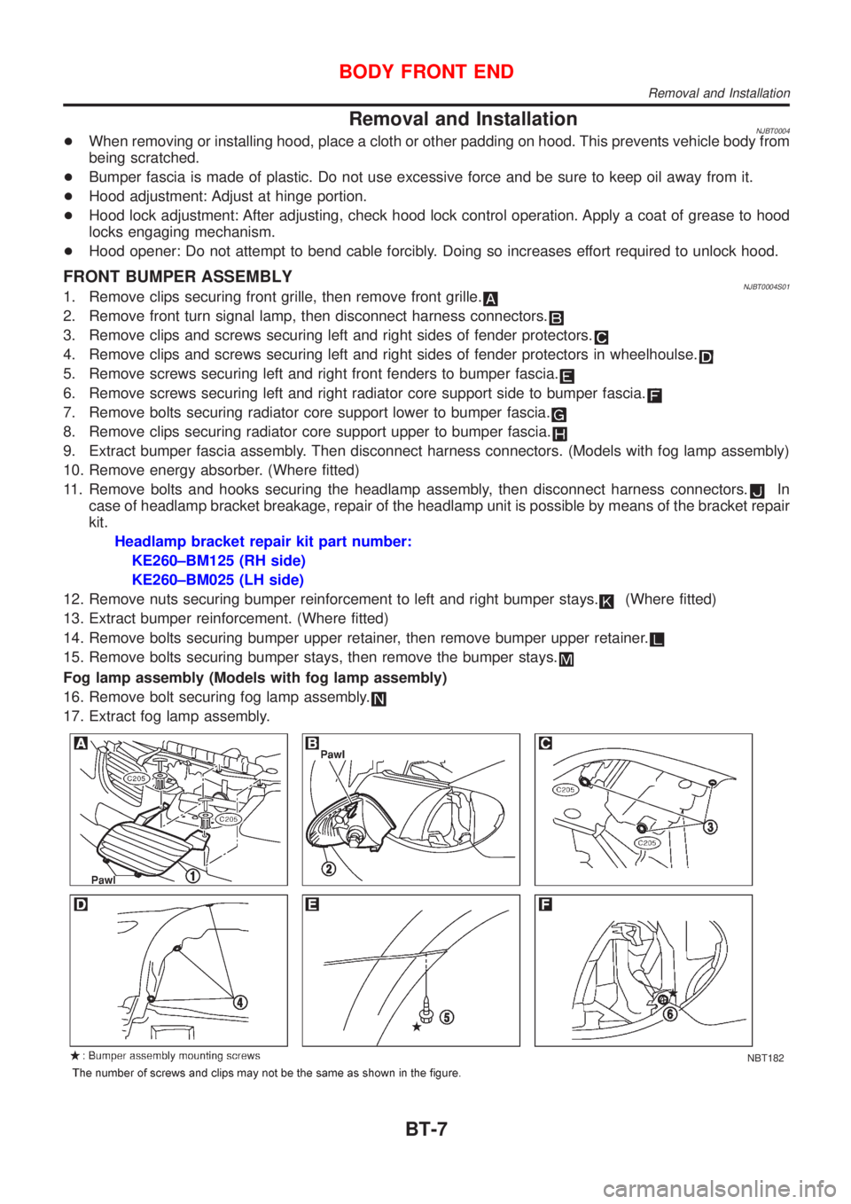
FRONT BUMPER ASSEMBLYNJBT0004S011. Remove clips securing front grille, then remove front grille.
2. Remove front turn signal lamp, then disconnect harness connectors.
3. Remove clips and screws securing left and right sides of fender protectors.
4. Remove clips and screws securing left and right sides of fender protectors in wheelhoulse.
5. Remove screws securing left and right front fenders to bumper fascia.
6. Remove screws securing left and right radiator core support side to bumper fascia.
7. Remove bolts securing radiator core support lower to bumper fascia.
8. Remove clips securing radiator core support upper to bumper fascia.
9. Extract bumper fascia assembly. Then disconnect harness connectors. (Models with fog lamp assembly)
10. Remove energy absorber. (Where fitted)
11. Remove bolts and hooks securing the headlamp assembly, then disconnect harness connectors.
In
case of headlamp bracket breakage, repair of the headlamp unit is possible by means of the bracket repair
kit.
Headlamp bracket repair kit part number:
KE260±BM125 (RH side)
KE260±BM025 (LH side)
12. Remove nuts securing bumper reinforcement to left and right bumper stays.
(Where fitted)
13. Extract bumper reinforcement. (Where fitted)
14. Remove bolts securing bumper upper retainer, then remove bumper upper retainer.
15. Remove bolts securing bumper stays, then remove the bumper stays.
Fog lamp assembly (Models with fog lamp assembly)
16. Remove bolt securing fog lamp assembly.
17. Extract fog lamp assembly.
NBT182
BODY FRONT END
Removal and Installation
BT-7
Page 2066 of 2493

Heater & Cooling Unit (Heater Core)
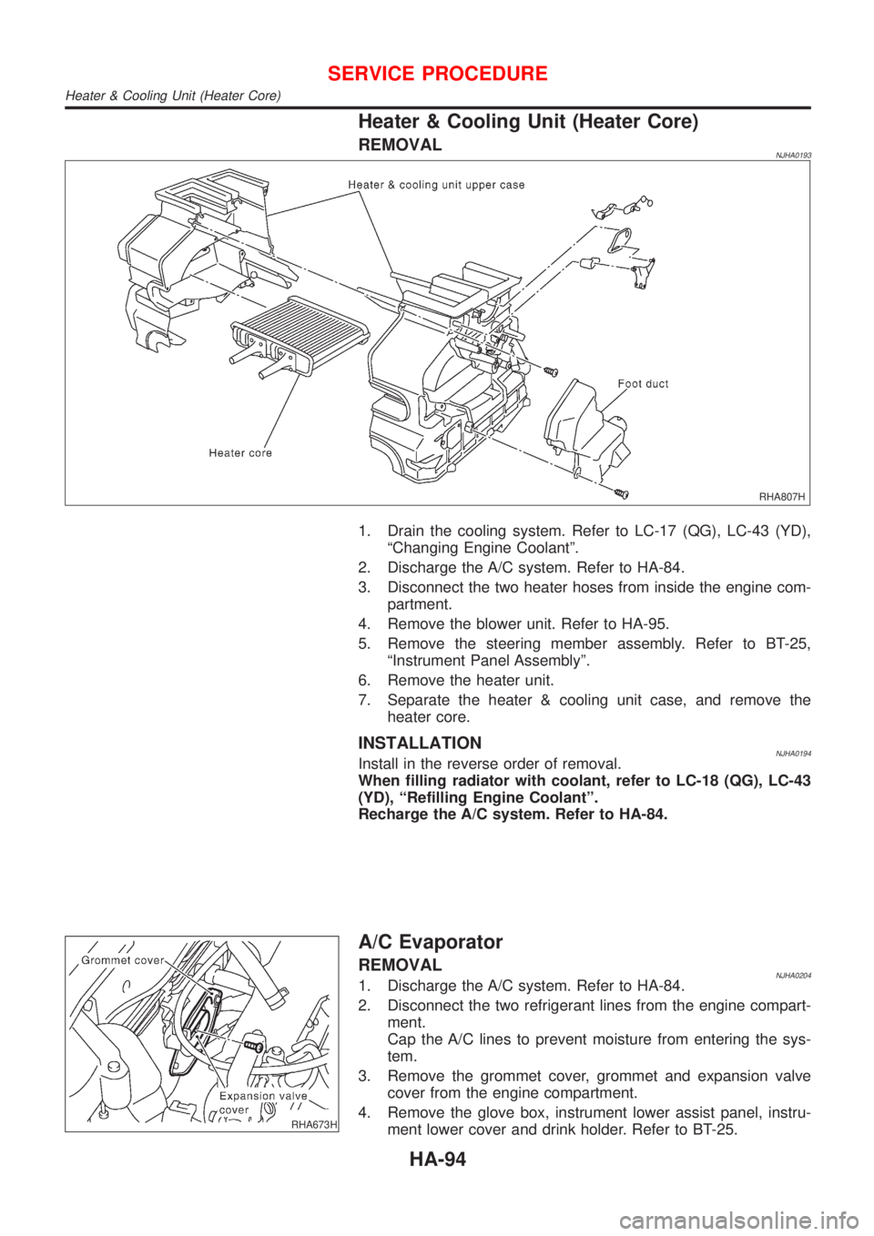
REMOVALNJHA0193
RHA807H
1. Drain the cooling system. Refer to LC-17 (QG), LC-43 (YD),
ªChanging Engine Coolantº.
2. Discharge the A/C system. Refer to HA-84.
3. Disconnect the two heater hoses from inside the engine com-
partment.
4. Remove the blower unit. Refer to HA-95.
5. Remove the steering member assembly. Refer to BT-25,
ªInstrument Panel Assemblyº.
6. Remove the heater unit.
7. Separate the heater & cooling unit case, and remove the
heater core.
INSTALLATIONNJHA0194Install in the reverse order of removal.
When filling radiator with coolant, refer to LC-18 (QG), LC-43
(YD), ªRefilling Engine Coolantº.
Recharge the A/C system. Refer to HA-84.
RHA673H
A/C Evaporator
REMOVALNJHA02041. Discharge the A/C system. Refer to HA-84.
2. Disconnect the two refrigerant lines from the engine compart-
ment.
Cap the A/C lines to prevent moisture from entering the sys-
tem.
3. Remove the grommet cover, grommet and expansion valve
cover from the engine compartment.
4. Remove the glove box, instrument lower assist panel, instru-
ment lower cover and drink holder. Refer to BT-25.
SERVICE PROCEDURE
Heater & Cooling Unit (Heater Core)
HA-94
Page 2486 of 2493

O
Oil pan (engine) .................................. EM-19, 88
Oil pressure (engine) ............................ LC-5, 27
Oil pump (A/T) ......................................... AT-371
Oil pump (engine) ................................. LC-5, 27
Oil pump regulator valve (engine) ......... LC-7, 29
Oil seal replacement (engine) .................. EM-31
On board diagnostic system ............. EC-57, 522
Operating cylinder (clutch) ........................ CL-14
Overdrive control switch .......................... AT-333
Overrun clutch .......................................... AT-399
P
PCV (positive crankcase ventilation) ....... EC-37,
508
PGC/V - Wiring diagram ................. EC-306, 413
PNP/SW - Wiring diagram ...... EC-366, 442, 696
POWER - Wiring diagram ......................... EL-12
PST/SW - Wiring diagram ....................... EC-471
Park/Neutral position switch ... EC-364, 441, 696
Park/neutral position switch (A/T) ............ AT-181
Park/neutral position switch (M/T) ............ MT-21
Parking brake control ................................ BR-47
Parking lamp .............................................. EL-53
Piston assembly ............................... EM-60, 154
Piston pin inspection ........................ EM-54, 144
Piston ring inspection ....................... EM-54, 144
Piston to bore clearance .................. EM-56, 146
Power antenna ........................................ EL-162
Power door lock ....................................... EL-177
Power door mirror .................................... EL-167
Power steering fluid level ............................ ST-7
Power steering gear .................................. ST-15
Power steering hydraulic pressure .............. ST-9
Power steering oil pressure switch ......... EC-470
Power steering system bleeding ................. ST-8
Power supply routing ................................... EL-9
Power window ......................................... EL-169
Precautions (General) .................................. GI-4
Pressure plate - See Clutch cover ............ CL-22
Priming pump .................................. EC-520, 536
Q
Quick-glow system .................................. EC-677
R
RR02 - Wiring diagram .. EC-217, 225, 232, 239,
384
RR02/H - Wiring diagram ............... EC-245, 390
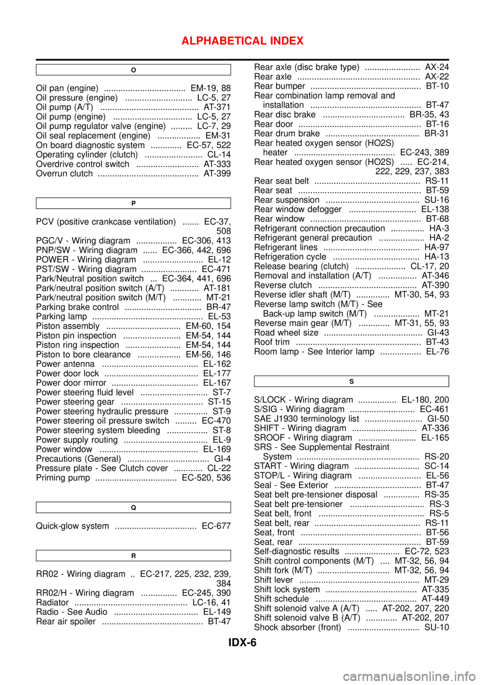
Radiator ............................................... LC-16, 41
Radio - See Audio ................................... EL-149
Rear air spoiler .......................................... BT-47Rear axle (disc brake type) ....................... AX-24
Rear axle ................................................... AX-22
Rear bumper .............................................. BT-10
Rear combination lamp removal and
installation .............................................. BT-47
Rear disc brake .................................. BR-35, 43
Rear door ................................................... BT-16
Rear drum brake ....................................... BR-31
Rear heated oxygen sensor (HO2S)
heater .......................................... EC-243, 389
Rear heated oxygen sensor (HO2S) ..... EC-214,
222, 229, 237, 383
Rear seat belt ............................................ RS-11
Rear seat ................................................... BT-59
Rear suspension ....................................... SU-16
Rear window defogger ............................ EL-138
Rear window .............................................. BT-68
Refrigerant connection precaution .............. HA-3
Refrigerant general precaution ................... HA-2
Refrigerant lines ........................................ HA-97
Refrigeration cycle .................................... HA-13
Release bearing (clutch) ..................... CL-17, 20
Removal and installation (A/T) ................ AT-346
Reverse clutch ......................................... AT-390
Reverse idler shaft (M/T) .............. MT-30, 54, 93
Reverse lamp switch (M/T) - See
Back-up lamp switch (M/T) ................... MT-21
Reverse main gear (M/T) ............. MT-31, 55, 93
Road wheel size ......................................... GI-43
Roof trim .................................................... BT-43
Room lamp - See Interior lamp ................. EL-76
S
S/LOCK - Wiring diagram ................ EL-180, 200
S/SIG - Wiring diagram ........................... EC-461
SAE J1930 terminology list ........................ GI-50
SHIFT - Wiring diagram ........................... AT-336
SROOF - Wiring diagram ........................ EL-165
SRS - See Supplemental Restraint
System ................................................... RS-20
START - Wiring diagram ........................... SC-14
STOP/L - Wiring diagram .......................... EL-56
Seal - See Exterior .................................... BT-47
Seat belt pre-tensioner disposal ............... RS-35
Seat belt pre-tensioner ............................... RS-3
Seat belt, front ............................................ RS-5
Seat belt, rear ............................................ RS-11
Seat, front .................................................. BT-56
Seat, rear ................................................... BT-59
Self-diagnostic results ....................... EC-72, 523
Shift control components (M/T) .... MT-32, 56, 94
Shift fork (M/T) .............................. MT-32, 56, 94
Shift lever .................................................. MT-29
Shift lock system ...................................... AT-335
Shift schedule .......................................... AT-449
Shift solenoid valve A (A/T) ..... AT-202, 207, 220
Shift solenoid valve B (A/T) ............. AT-202, 207
Shock absorber (front) .............................. SU-10
ALPHABETICAL INDEX
IDX-6