2001 NISSAN ALMERA N16 electrical
[x] Cancel search: electricalPage 3 of 2493
GENERAL INFORMATION
SECTION
GI
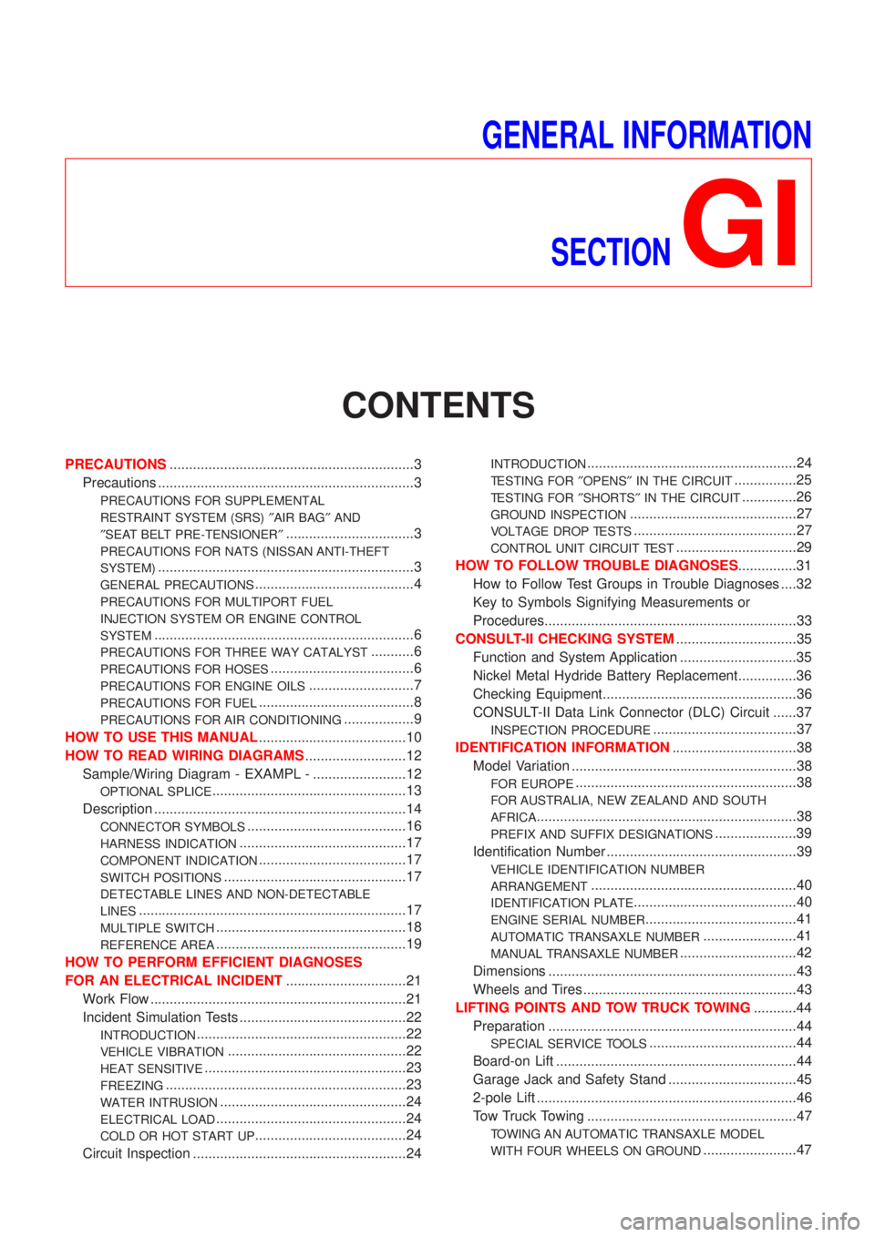
CONTENTS
PRECAUTIONS...............................................................3
Precautions ..................................................................3
PRECAUTIONS FOR SUPPLEMENTAL
RESTRAINT SYSTEM (SRS)²AIR BAG²AND
²SEAT BELT PRE-TENSIONER²
.................................3
PRECAUTIONS FOR NATS (NISSAN ANTI-THEFT
SYSTEM)
..................................................................3
GENERAL PRECAUTIONS.........................................4
PRECAUTIONS FOR MULTIPORT FUEL
INJECTION SYSTEM OR ENGINE CONTROL
SYSTEM
...................................................................6
PRECAUTIONS FOR THREE WAY CATALYST...........6
PRECAUTIONS FOR HOSES.....................................6
PRECAUTIONS FOR ENGINE OILS...........................7
PRECAUTIONS FOR FUEL........................................8
PRECAUTIONS FOR AIR CONDITIONING..................9
HOW TO USE THIS MANUAL......................................10
HOW TO READ WIRING DIAGRAMS..........................12
Sample/Wiring Diagram - EXAMPL - ........................12
OPTIONAL SPLICE..................................................13
Description .................................................................14
CONNECTOR SYMBOLS.........................................16
HARNESS INDICATION...........................................17
COMPONENT INDICATION......................................17
SWITCH POSITIONS...............................................17
DETECTABLE LINES AND NON-DETECTABLE
LINES
.....................................................................17
MULTIPLE SWITCH.................................................18
REFERENCE AREA.................................................19
HOW TO PERFORM EFFICIENT DIAGNOSES
FOR AN ELECTRICAL INCIDENT...............................21
Work Flow ..................................................................21
Incident Simulation Tests ...........................................22
INTRODUCTION......................................................22
VEHICLE VIBRATION..............................................22
HEAT SENSITIVE....................................................23
FREEZING..............................................................23
WATER INTRUSION................................................24
ELECTRICAL LOAD.................................................24
COLD OR HOT START UP.......................................24
Circuit Inspection .......................................................24
INTRODUCTION......................................................24
TESTING FOR²OPENS²IN THE CIRCUIT................25
TESTING FOR²SHORTS²IN THE CIRCUIT..............26
GROUND INSPECTION...........................................27
VOLTAGE DROP TESTS..........................................27
CONTROL UNIT CIRCUIT TEST...............................29
HOW TO FOLLOW TROUBLE DIAGNOSES...............31
How to Follow Test Groups in Trouble Diagnoses ....32
Key to Symbols Signifying Measurements or
Procedures.................................................................33
CONSULT-II CHECKING SYSTEM...............................35
Function and System Application ..............................35
Nickel Metal Hydride Battery Replacement...............36
Checking Equipment..................................................36
CONSULT-II Data Link Connector (DLC) Circuit ......37
INSPECTION PROCEDURE.....................................37
IDENTIFICATION INFORMATION................................38
Model Variation ..........................................................38
FOR EUROPE.........................................................38
FOR AUSTRALIA, NEW ZEALAND AND SOUTH
AFRICA
...................................................................38
PREFIX AND SUFFIX DESIGNATIONS.....................39
Identification Number .................................................39
VEHICLE IDENTIFICATION NUMBER
ARRANGEMENT
.....................................................40
IDENTIFICATION PLATE..........................................40
ENGINE SERIAL NUMBER.......................................41
AUTOMATIC TRANSAXLE NUMBER........................41
MANUAL TRANSAXLE NUMBER..............................42
Dimensions ................................................................43
Wheels and Tires .......................................................43
LIFTING POINTS AND TOW TRUCK TOWING...........44
Preparation ................................................................44
SPECIAL SERVICE TOOLS......................................44
Board-on Lift ..............................................................44
Garage Jack and Safety Stand .................................45
2-pole Lift ...................................................................46
Tow Truck Towing ......................................................47
TOWING AN AUTOMATIC TRANSAXLE MODEL
WITH FOUR WHEELS ON GROUND
........................47
Page 5 of 2493

PrecautionsNJGI0001Observe the following precautions to ensure safe and proper
servicing. These precautions are not described in each indi-
vidual section.
SGI646
PRECAUTIONS FOR SUPPLEMENTAL RESTRAINT
SYSTEM (SRS) ªAIR BAGº AND ªSEAT BELT
PRE-TENSIONERº
NJGI0001S01The Supplemental Restraint System such as ªAIR BAGº and ªSEAT
BELT PRE-TENSIONERº used along with a seat belt, helps to
reduce the risk or severity of injury to the driver and front passen-
ger for certain types of collision. The SRS system composition
which is available to NISSAN MODEL N16 is as follows (The com-
position varies according to the destination and optional equip-
ment.):
+For a frontal collision
The Supplemental Restraint System consists of driver air bag
module (located in the center of the steering wheel), front pas-
senger air bag module (located on the instrument panel on
passenger side), front seat belt pre-tensioners, a diagnoses
sensor unit, warning lamp, wiring harness and spiral cable.
+For a side collision
The Supplemental Restraint System consists of front side air
bag module (located in the outer side of front seat), side air bag
(satellite) sensor, diagnoses sensor unit (one of components of
air bags for a frontal collision), wiring harness, warning lamp
(one of components of air bags for a frontal collision).
Information necessary to service the system safely is included in
theRS sectionof this Service Manual.
WARNING:
+To avoid rendering the SRS inoperative, which could
increase the risk of personal injury or death in the event
of a collision which would result in air bag inflation, all
maintenance should be performed by an authorized
NISSAN dealer.
+Improper maintenance, including incorrect removal and
installation of the SRS, can lead to personal injury caused
by unintentional activation of the system. For removal of
Spiral Cable and Air Bag Module, see the RS section.
+Do not use electrical test equipment on any circuit related
to the SRS unless instructed to in this Service Manual.
SRS wiring harnesses can be identified by yellow harness
connector.
PRECAUTIONS FOR NATS (NISSAN ANTI-THEFT
SYSTEM)
NJGI0001S02NATS will immobilize the engine if someone tries to start it without
the registered key of NATS.
Both of the originally supplied ignition key IDs have been NATS
registered.
PRECAUTIONS
Precautions
GI-3
Page 7 of 2493
SEF289H
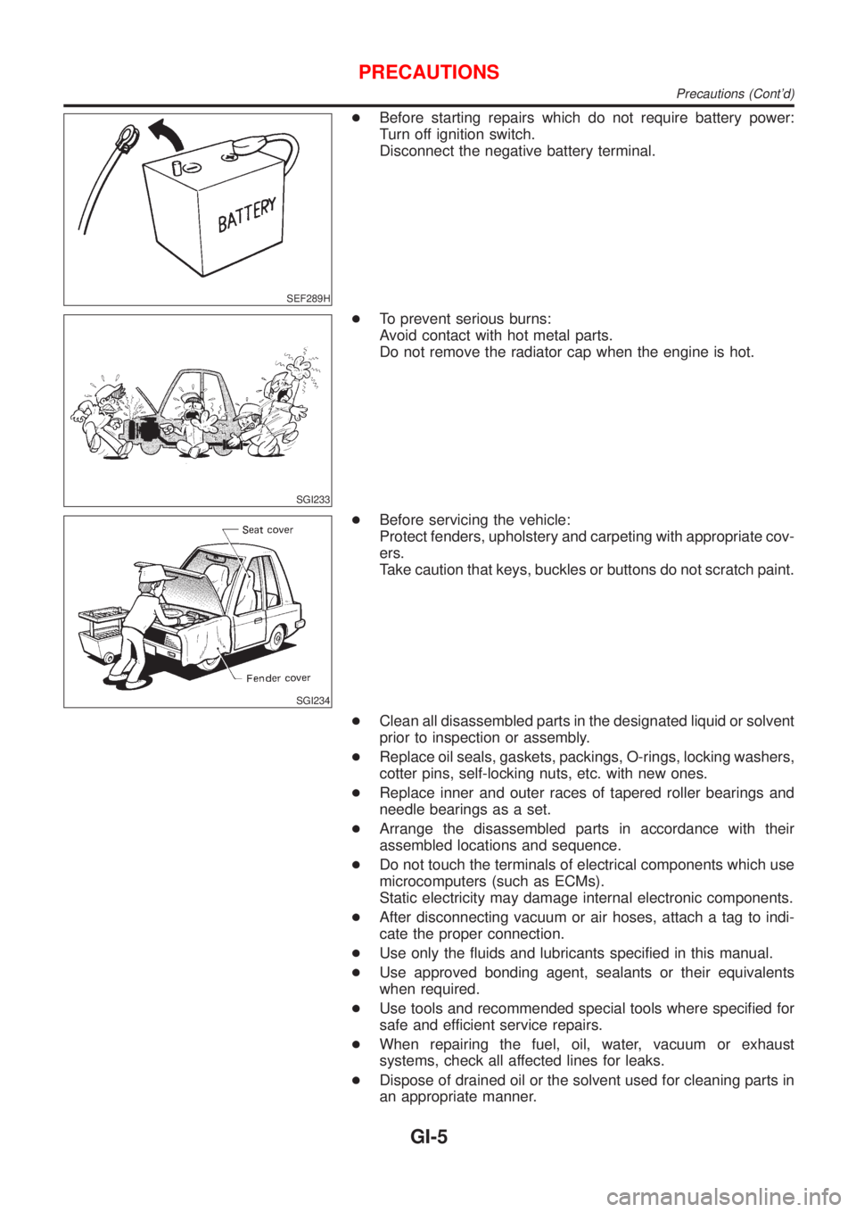
+Before starting repairs which do not require battery power:
Turn off ignition switch.
Disconnect the negative battery terminal.
SGI233
+To prevent serious burns:
Avoid contact with hot metal parts.
Do not remove the radiator cap when the engine is hot.
SGI234
+Before servicing the vehicle:
Protect fenders, upholstery and carpeting with appropriate cov-
ers.
Take caution that keys, buckles or buttons do not scratch paint.
+Clean all disassembled parts in the designated liquid or solvent
prior to inspection or assembly.
+Replace oil seals, gaskets, packings, O-rings, locking washers,
cotter pins, self-locking nuts, etc. with new ones.
+Replace inner and outer races of tapered roller bearings and
needle bearings as a set.
+Arrange the disassembled parts in accordance with their
assembled locations and sequence.
+Do not touch the terminals of electrical components which use
microcomputers (such as ECMs).
Static electricity may damage internal electronic components.
+After disconnecting vacuum or air hoses, attach a tag to indi-
cate the proper connection.
+Use only the fluids and lubricants specified in this manual.
+Use approved bonding agent, sealants or their equivalents
when required.
+Use tools and recommended special tools where specified for
safe and efficient service repairs.
+When repairing the fuel, oil, water, vacuum or exhaust
systems, check all affected lines for leaks.
+Dispose of drained oil or the solvent used for cleaning parts in
an appropriate manner.
PRECAUTIONS
Precautions (Cont'd)
GI-5
Page 17 of 2493
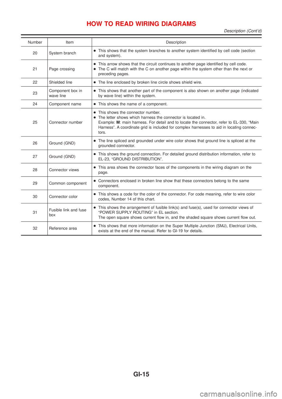
Number Item Description
20 System branch+This shows that the system branches to another system identified by cell code (section
and system).
21 Page crossing+This arrow shows that the circuit continues to another page identified by cell code.
+The C will match with the C on another page within the system other than the next or
preceding pages.
22 Shielded line+The line enclosed by broken line circle shows shield wire.
23Component box in
wave line+This shows that another part of the component is also shown on another page (indicated
by wave line) within the system.
24 Component name+This shows the name of a component.
25 Connector number+This shows the connector number.
+The letter shows which harness the connector is located in.
Example:M: main harness. For detail and to locate the connector, refer to EL-330, ªMain
Harnessº. A coordinate grid is included for complex harnesses to aid in locating connec-
tors.
26 Ground (GND)+The line spliced and grounded under wire color shows that ground line is spliced at the
grounded connector.
27 Ground (GND)+This shows the ground connection. For detailed ground distribution information, refer to
EL-23, ªGROUND DISTRIBUTIONº.
28 Connector views+This area shows the connector faces of the components in the wiring diagram on the
page.
29 Common component+Connectors enclosed in broken line show that these connectors belong to the same
component.
30 Connector color+This shows a code for the color of the connector. For code meaning, refer to wire color
codes, Number 14 of this chart.
31Fusible link and fuse
box+This shows the arrangement of fusible link(s) and fuse(s), used for connector views of
ªPOWER SUPPLY ROUTINGº in EL section.
The open square shows current flow in, and the shaded square shows current flow out.
32 Reference area+This shows that more information on the Super Multiple Junction (SMJ), Electrical Units,
exists at the end of the manual. Refer to GI-19 for details.
HOW TO READ WIRING DIAGRAMS
Description (Cont'd)
GI-15
Page 21 of 2493
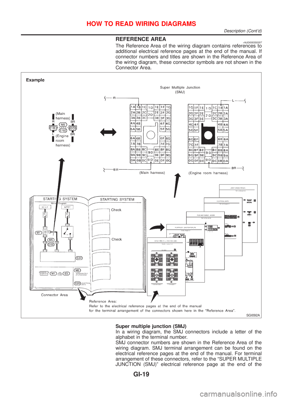
REFERENCE AREA=NJGI0003S0207The Reference Area of the wiring diagram contains references to
additional electrical reference pages at the end of the manual. If
connector numbers and titles are shown in the Reference Area of
the wiring diagram, these connector symbols are not shown in the
Connector Area.
SGI092A
Super multiple junction (SMJ)
In a wiring diagram, the SMJ connectors include a letter of the
alphabet in the terminal number.
SMJ connector numbers are shown in the Reference Area of the
wiring diagram. SMJ terminal arrangement can be found on the
electrical reference pages at the end of the manual. For terminal
arrangement of these connectors, refer to the ªSUPER MULTIPLE
JUNCTION (SMJ)º electrical reference page at the end of the
HOW TO READ WIRING DIAGRAMS
Description (Cont'd)
GI-19
Page 22 of 2493
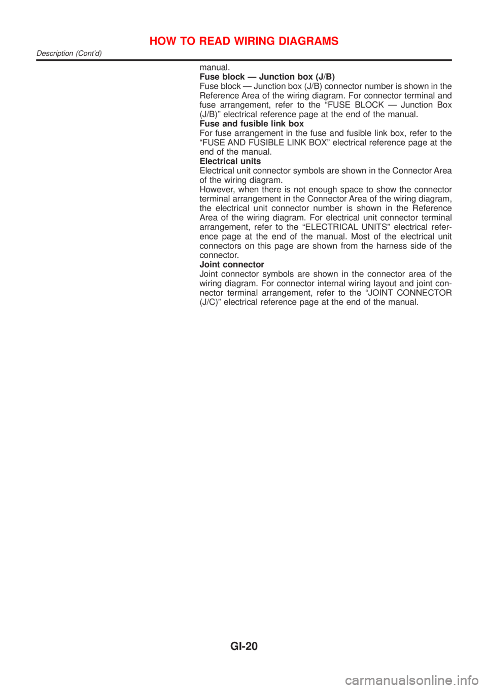
manual.
Fuse block Ð Junction box (J/B)
Fuse block Ð Junction box (J/B) connector number is shown in the
Reference Area of the wiring diagram. For connector terminal and
fuse arrangement, refer to the ªFUSE BLOCK Ð Junction Box
(J/B)º electrical reference page at the end of the manual.
Fuse and fusible link box
For fuse arrangement in the fuse and fusible link box, refer to the
ªFUSE AND FUSIBLE LINK BOXº electrical reference page at the
end of the manual.
Electrical units
Electrical unit connector symbols are shown in the Connector Area
of the wiring diagram.
However, when there is not enough space to show the connector
terminal arrangement in the Connector Area of the wiring diagram,
the electrical unit connector number is shown in the Reference
Area of the wiring diagram. For electrical unit connector terminal
arrangement, refer to the ªELECTRICAL UNITSº electrical refer-
ence page at the end of the manual. Most of the electrical unit
connectors on this page are shown from the harness side of the
connector.
Joint connector
Joint connector symbols are shown in the connector area of the
wiring diagram. For connector internal wiring layout and joint con-
nector terminal arrangement, refer to the ªJOINT CONNECTOR
(J/C)º electrical reference page at the end of the manual.
HOW TO READ WIRING DIAGRAMS
Description (Cont'd)
GI-20
Page 23 of 2493
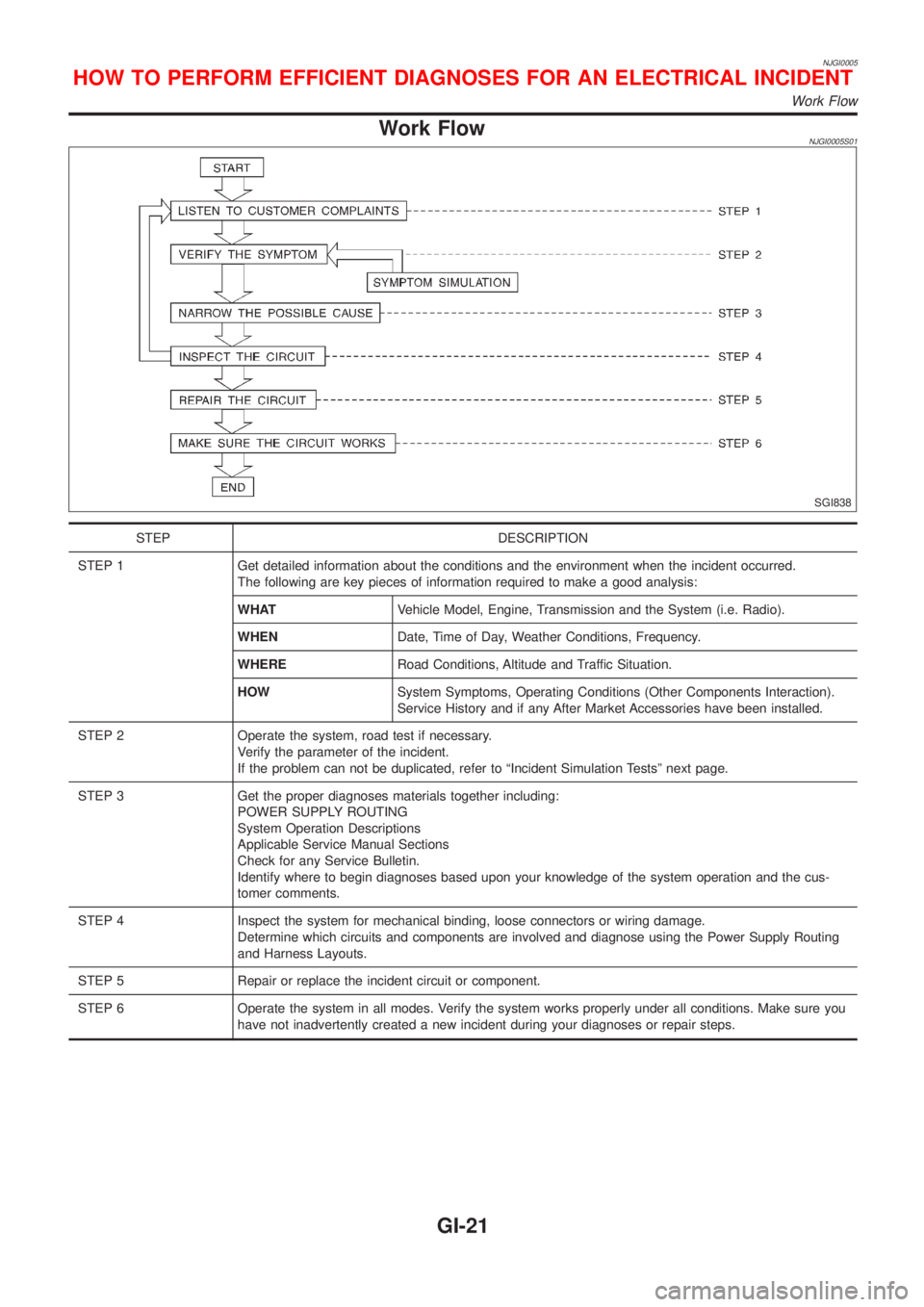
NJGI0005
Work FlowNJGI0005S01
SGI838
STEP DESCRIPTION
STEP 1 Get detailed information about the conditions and the environment when the incident occurred.
The following are key pieces of information required to make a good analysis:
WHATVehicle Model, Engine, Transmission and the System (i.e. Radio).
WHENDate, Time of Day, Weather Conditions, Frequency.
WHERERoad Conditions, Altitude and Traffic Situation.
HOWSystem Symptoms, Operating Conditions (Other Components Interaction).
Service History and if any After Market Accessories have been installed.
STEP 2 Operate the system, road test if necessary.
Verify the parameter of the incident.
If the problem can not be duplicated, refer to ªIncident Simulation Testsº next page.
STEP 3 Get the proper diagnoses materials together including:
POWER SUPPLY ROUTING
System Operation Descriptions
Applicable Service Manual Sections
Check for any Service Bulletin.
Identify where to begin diagnoses based upon your knowledge of the system operation and the cus-
tomer comments.
STEP 4 Inspect the system for mechanical binding, loose connectors or wiring damage.
Determine which circuits and components are involved and diagnose using the Power Supply Routing
and Harness Layouts.
STEP 5 Repair or replace the incident circuit or component.
STEP 6 Operate the system in all modes. Verify the system works properly under all conditions. Make sure you
have not inadvertently created a new incident during your diagnoses or repair steps.
HOW TO PERFORM EFFICIENT DIAGNOSES FOR AN ELECTRICAL INCIDENT
Work Flow
GI-21
Page 24 of 2493
Incident Simulation TestsNJGI0005S02INTRODUCTIONNJGI0005S0201Sometimes the symptom is not present when the vehicle is brought
in for service. If possible, re-create the conditions present at the
time of the incident. Doing so may help avoid a No Trouble Found
Diagnoses. The following section illustrates ways to simulate the
conditions/environment under which the owner experiences an
electrical incident.
The section is broken into the six following topics:
+Vehicle vibration
+Heat sensitive
+Freezing
+Water intrusion
+Electrical load
+Cold or hot start up
Get a thorough description of the incident from the customer. It is
important for simulating the conditions of the problem.
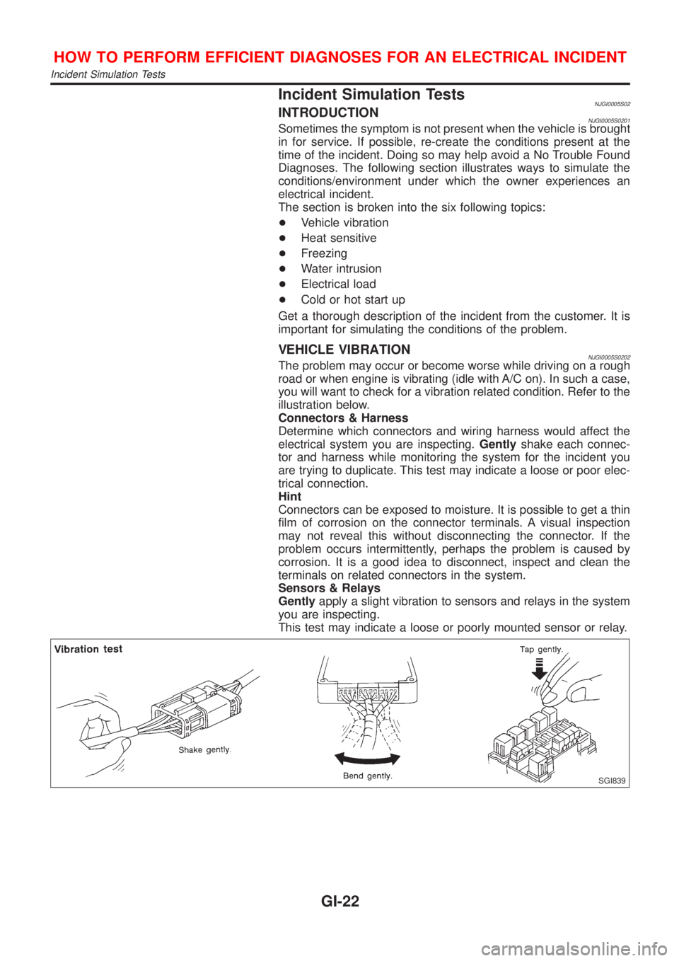
VEHICLE VIBRATIONNJGI0005S0202The problem may occur or become worse while driving on a rough
road or when engine is vibrating (idle with A/C on). In such a case,
you will want to check for a vibration related condition. Refer to the
illustration below.
Connectors & Harness
Determine which connectors and wiring harness would affect the
electrical system you are inspecting.Gentlyshake each connec-
tor and harness while monitoring the system for the incident you
are trying to duplicate. This test may indicate a loose or poor elec-
trical connection.
Hint
Connectors can be exposed to moisture. It is possible to get a thin
film of corrosion on the connector terminals. A visual inspection
may not reveal this without disconnecting the connector. If the
problem occurs intermittently, perhaps the problem is caused by
corrosion. It is a good idea to disconnect, inspect and clean the
terminals on related connectors in the system.
Sensors & Relays
Gentlyapply a slight vibration to sensors and relays in the system
you are inspecting.
This test may indicate a loose or poorly mounted sensor or relay.
SGI839
HOW TO PERFORM EFFICIENT DIAGNOSES FOR AN ELECTRICAL INCIDENT
Incident Simulation Tests
GI-22