2001 NISSAN ALMERA N16 electrical
[x] Cancel search: electricalPage 2434 of 2493
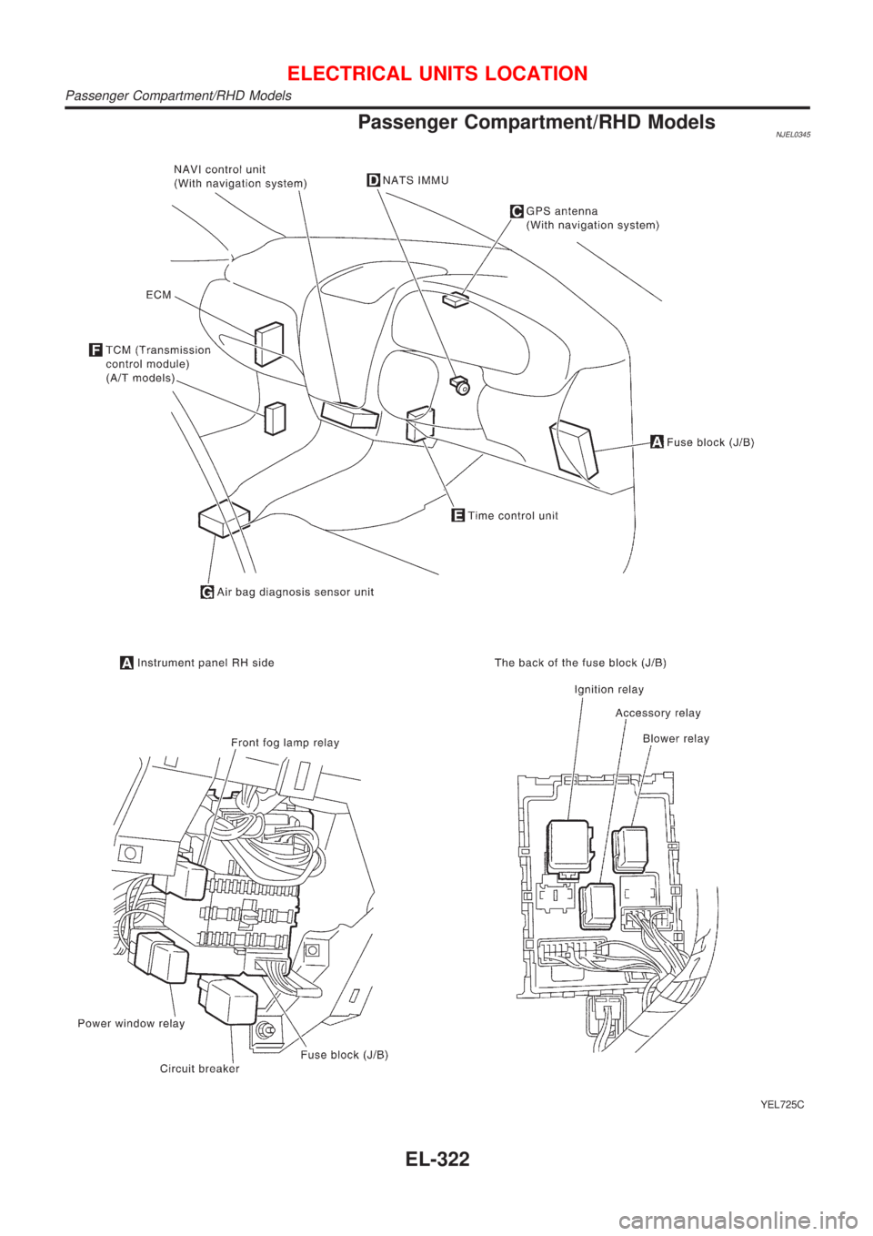
Passenger Compartment/RHD ModelsNJEL0345
YEL725C
ELECTRICAL UNITS LOCATION
Passenger Compartment/RHD Models
EL-322
Page 2435 of 2493
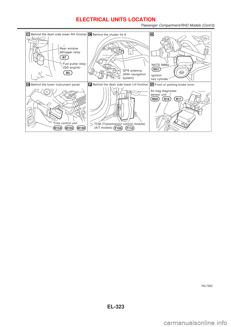
YEL726C
ELECTRICAL UNITS LOCATION
Passenger Compartment/RHD Models (Cont'd)
EL-323
Page 2483 of 2493
CONSULT for ABS .................................... BR-58
CONSULT for engine ........................ EC-81, 527
COOL/F - Wiring diagram ............... EC-337, 618
Camshaft inspection ......................... EM-36, 122
Camshaft position sensor (CMPS) ......... EC-278
Camshaft position sensor (PHASE) ........ EC-278
Canister - See EVAP canister ................... EC-33
Charging system ....................................... SC-24
Cigarette lighter ....................................... EL-136
Circuit breaker ........................................... EL-22
Closed throttle position switch ....... EC-321, 426
Clutch cover .............................................. CL-22
Clutch disc ................................................. CL-22
Clutch master cylinder ............................... CL-11
Clutch operating cylinder ........................... CL-14
Clutch pedal .............................................. CL-10
Clutch release bearing ........................ CL-17, 20
Clutch release mechanism .................. CL-17, 20
Clutch withdrawal lever ....................... CL-17, 20
Coil spring (front) ........................................ SU-9
Coil spring (rear) ....................................... SU-21
Collision diagnosis .................................... RS-71
Combination lamp, rear, removal and
installation .............................................. BT-47
Combination meter removal and instal-
lation - See Instrument panel ................ BT-25
Combination meter .................................... EL-89
Combination switch ................................... EL-37
Compression pressure ............................. EM-82
Compressor clutch removal and
installation .............................................. HA-89
Compressor precaution ............................... HA-5
Compressor special service tool ................. HA-9
Connecting rod bearing clearance ... EM-58, 150
Connecting rod bushing clearance ... EM-59, 152
Connecting rod ................................. EM-55, 145
Console box - See Instrument panel ......... BT-25
Control lever (M/T) .................................... MT-29
Control valve (A/T) ................................... AT-375
Converter housing installation ................. AT-347
Coolant mixture ratio ................................ MA-22
Cooling circuit (engine) ....................... LC-12, 36
Cooling fan control system .................. LC-17, 42
Cooling fan control .......................... EC-334, 618
Cooling fan motor ................................... EC-346
Cooling fan relay ..................................... EC-345
Coupling sleeve (M/T) .................. MT-31, 55, 93
Crankcase emission control system -
See Positive crankcase ventilation ...... EC-37,
508
Crankcase ventilation system - See
Positive crankcase ventilation ....... EC-37, 508
Crankshaft position sensor (OBD) .. EC-272, 394
Crankshaft position sensor (POS) .. EC-272, 394
Crankshaft position sensor (TDC) .......... EC-587
Crankshaft ........................................ EM-57, 148
Cylinder block ................................... EM-52, 139
Cylinder head .................................... EM-33, 118D
DEF - Wiring diagram .............................. EL-140
DTC work support ..................................... EC-90
Data link connector for Consult ........ EC-38, 527
Daytime light system ................................. EL-44
Detonation sensor - See Knock
sensor .................................................. EC-268
Diagnosis sensor unit ............................... RS-26
Diagnostic trouble code (DTC) for
OBD system .................... EC-10, 70, 492, 522
Diagnostic trouble code (DTC) inspec-
tion priority chart .................................. EC-122
Differential gear (FF A/T) ......................... AT-424
Differential gear (FF M/T) ...... MT-31, 43, 55, 93,
107
Dimensions ................................................. GI-43
Dome light - See Interior lamp .................. EL-76
Door glass ................................................. BT-17
Door lock ................................................... BT-21
Door mirror ................................................ BT-72
Door trim .................................................... BT-39
Door, front .................................................. BT-16
Door, rear ................................................... BT-16
Drive plate runout ..................................... EM-60
Drive shaft (front) ...................................... AX-10
Dropping resistor (A/T) .................... AT-180, 243
Dual pressure switch ................................ HA-13
E
ECCS-D control module ........ EC-554, 604, 664,
666, 670, 672
ECM input/output signal ................. EC-132, 554
ECTS - Wiring diagram ................... EC-165, 572
EGR control valve ................................... EC-359
EGR temperature sensor ........................ EC-347
EGR volume control valve ...................... EC-686
EGR/TS - Wiring diagram ....................... EC-350
EGRC1 - Wiring diagram ....... EC-289, 357, 403,
688
EVAP canister purge volume control
solenoid valve ........................................ EC-34
EVAP canister purge volume control
valve ............................................ EC-304, 411
EVAP canister ........................................... EC-34
Electric sunroof ........................................ EL-165
Electrical diagnoses ................................... GI-21
Electrical ignition system .......................... EC-31
Electrical load signal circuit ..................... EC-480
Electrical unit ........................................... EL-371
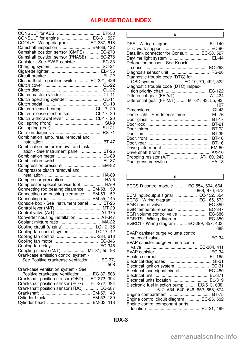
Electrical units location ............................ EL-319
Electronic fuel injection pump ........ EC-513, 606,
612, 634, 640, 646, 652, 658, 674
Engine compartment ................................. BT-75
Engine control circuit diagram .......... EC-25, 502
Engine control component parts
location .......................................... EC-21, 499
ALPHABETICAL INDEX
IDX-3
Page 2485 of 2493
Heated oxygen sensor (HO2S) heater
(rear) ............................................ EC-243, 389
Heated oxygen sensor (rear) ......... EC-214, 222,
229, 237, 383
Heated seat ............................................. EL-163
Height (Dimensions) ................................... GI-43
High clutch ............................................... AT-394
Hood ............................................................ BT-7
Horn ......................................................... EL-135
How to erase DTC for OBD system .. EC-68, 71,
522
I
IACV-AAC valve .............................. EC-313, 418
IATS - Wiring diagram .................... EC-160, 370
IGN/SG - Wiring diagram ........................ EC-452
ILL - Wiring diagram .................................. EL-72
INJECT - Wiring diagram ........................ EC-447
INT/L - Wiring diagram .............................. EL-87
IVC - Wiring diagram ...................... EC-331, 433
Identification plate ...................................... GI-40
Idle air control (IAC) system ........... EC-313, 418
Idle air control valve (IACV) ............ EC-313, 418
Idle speed ......................................... EC-41, 536
Ignition timing ............................................ EC-41
Illumination ................................................. EL-71
Injection nozzle ....................................... EC-509
Injector removal and installation ............... EC-39
Input shaft (FF M/T) ............... MT-36, 64, 93, 98
Instrument panel ........................................ BT-25
Intake air temperature sensor ......... EC-158, 369
Intake valve timing control solenoid
valve ............................................ EC-329, 432
Interior lamp on-off control ........................ EL-77
Interior lamp ............................................... EL-76
Interior ........................................................ BT-31
J
Jacking points ............................................ GI-45
Joint connector (J/C) ............................... EL-372
Junction box (J/B) .................................... EL-369
K
Keyless entry system - See Multi-remote control
system ..................................................... EL-220
Knock sensor (KS) .......................... EC-268, 269
Knuckle spindle ........................................... AX-5
L
LOAD - Wiring diagram .......................... EC-481
Length (Dimensions) .................................. GI-43
License lamp ............................................. EL-53Lifting points ............................................... GI-46
Line pressure solenoid valve ................... AT-230
Line pressure test (A/T) ............................. AT-82
Liquid gasket application ...................... EM-4, 76
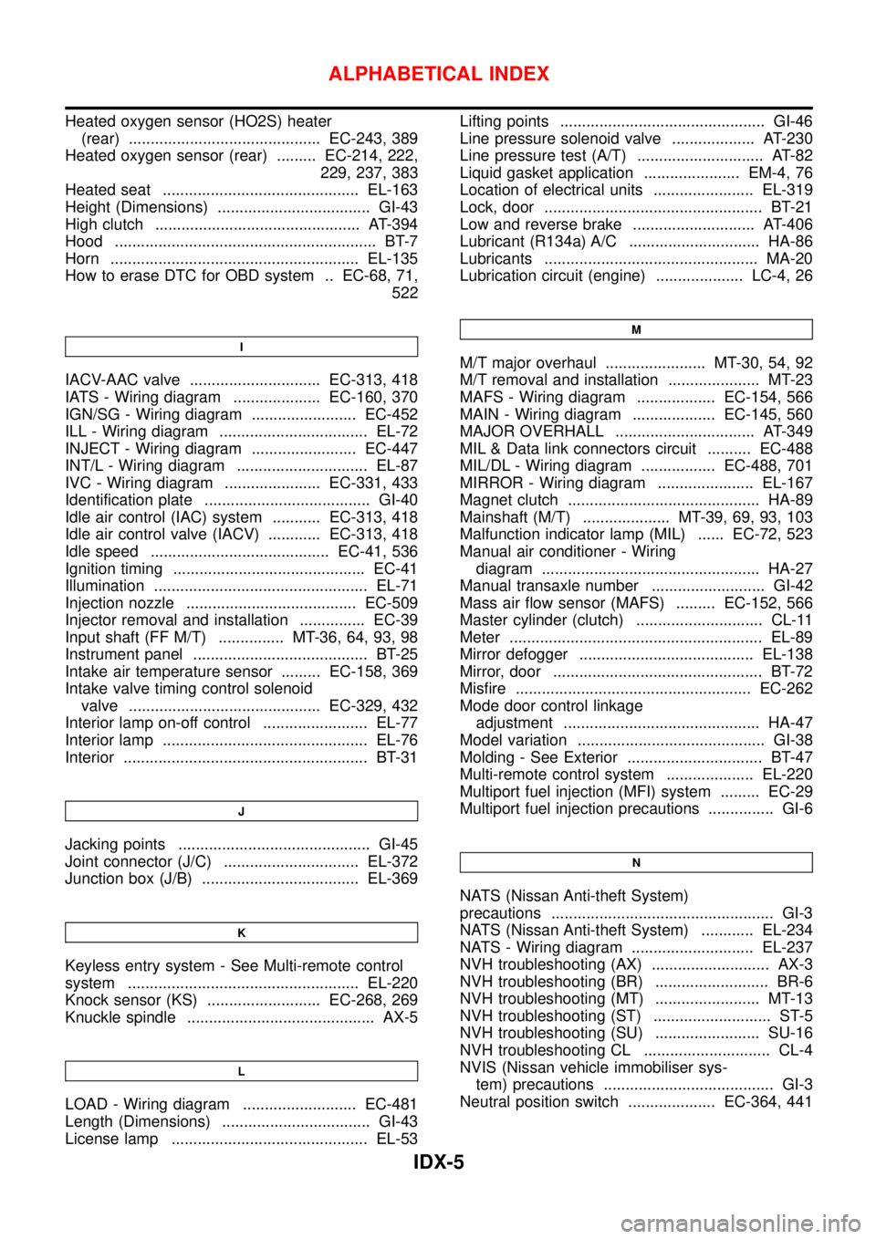
Location of electrical units ....................... EL-319
Lock, door .................................................. BT-21
Low and reverse brake ............................ AT-406
Lubricant (R134a) A/C .............................. HA-86
Lubricants ................................................. MA-20
Lubrication circuit (engine) .................... LC-4, 26
M
M/T major overhaul ....................... MT-30, 54, 92
M/T removal and installation ..................... MT-23
MAFS - Wiring diagram .................. EC-154, 566
MAIN - Wiring diagram ................... EC-145, 560
MAJOR OVERHALL ................................ AT-349
MIL & Data link connectors circuit .......... EC-488
MIL/DL - Wiring diagram ................. EC-488, 701
MIRROR - Wiring diagram ...................... EL-167
Magnet clutch ............................................ HA-89
Mainshaft (M/T) .................... MT-39, 69, 93, 103
Malfunction indicator lamp (MIL) ...... EC-72, 523
Manual air conditioner - Wiring
diagram .................................................. HA-27
Manual transaxle number .......................... GI-42
Mass air flow sensor (MAFS) ......... EC-152, 566
Master cylinder (clutch) ............................. CL-11
Meter .......................................................... EL-89
Mirror defogger ........................................ EL-138
Mirror, door ................................................ BT-72
Misfire ...................................................... EC-262
Mode door control linkage
adjustment ............................................. HA-47
Model variation ........................................... GI-38
Molding - See Exterior ............................... BT-47
Multi-remote control system .................... EL-220
Multiport fuel injection (MFI) system ......... EC-29
Multiport fuel injection precautions ............... GI-6
N
NATS (Nissan Anti-theft System)
precautions ................................................... GI-3
NATS (Nissan Anti-theft System) ............ EL-234
NATS - Wiring diagram ............................ EL-237
NVH troubleshooting (AX) ........................... AX-3
NVH troubleshooting (BR) .......................... BR-6
NVH troubleshooting (MT) ........................ MT-13
NVH troubleshooting (ST) ........................... ST-5
NVH troubleshooting (SU) ........................ SU-16
NVH troubleshooting CL ............................. CL-4
NVIS (Nissan vehicle immobiliser sys-
tem) precautions ....................................... GI-3
Neutral position switch .................... EC-364, 441
ALPHABETICAL INDEX
IDX-5
Page 2492 of 2493
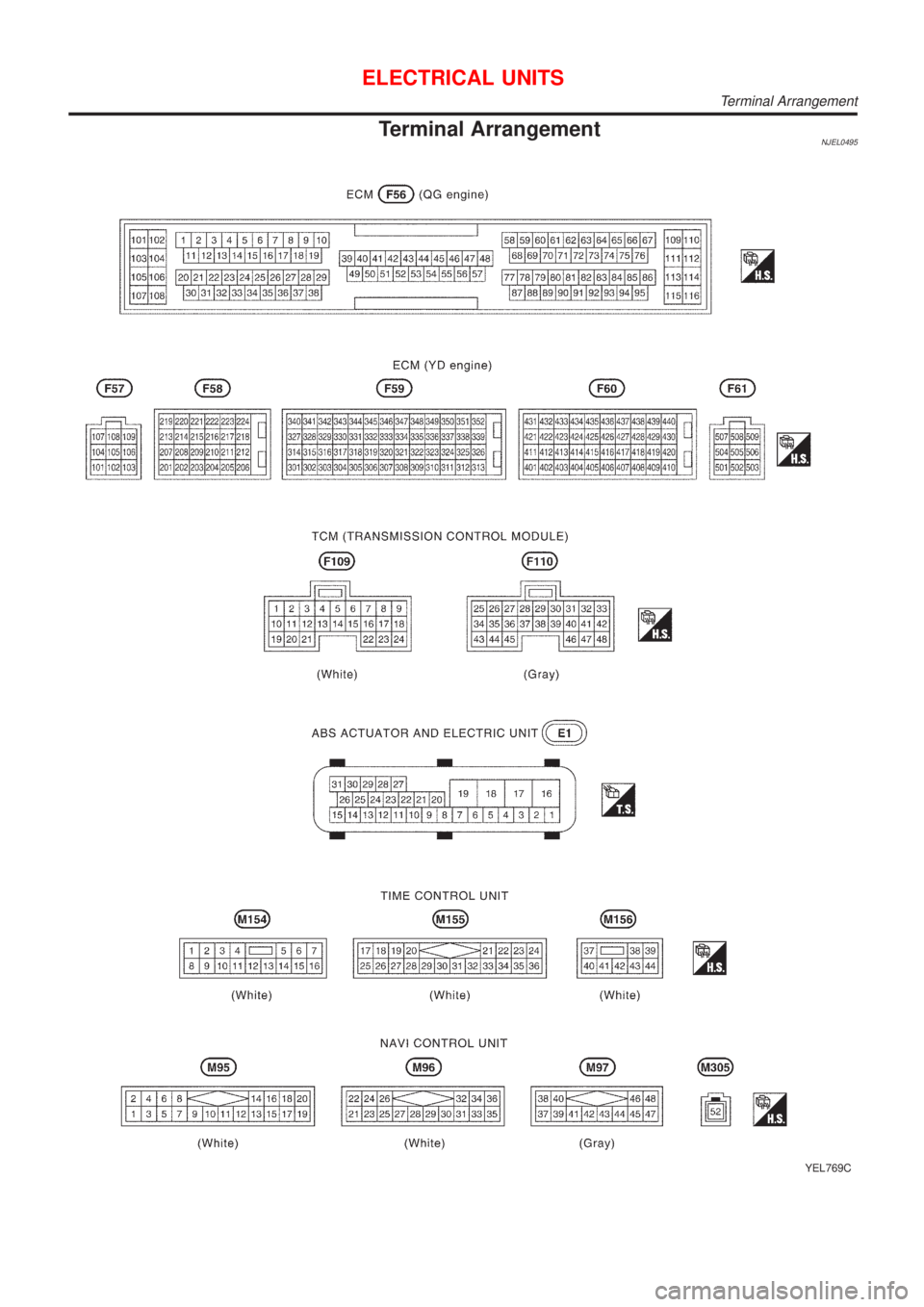
Terminal ArrangementNJEL0495
YEL769C
ELECTRICAL UNITS
Terminal Arrangement