2001 NISSAN ALMERA N16 Water sensor
[x] Cancel search: Water sensorPage 24 of 2493

Incident Simulation TestsNJGI0005S02INTRODUCTIONNJGI0005S0201Sometimes the symptom is not present when the vehicle is brought
in for service. If possible, re-create the conditions present at the
time of the incident. Doing so may help avoid a No Trouble Found
Diagnoses. The following section illustrates ways to simulate the
conditions/environment under which the owner experiences an
electrical incident.
The section is broken into the six following topics:
+Vehicle vibration
+Heat sensitive
+Freezing
+Water intrusion
+Electrical load
+Cold or hot start up
Get a thorough description of the incident from the customer. It is
important for simulating the conditions of the problem.
VEHICLE VIBRATIONNJGI0005S0202The problem may occur or become worse while driving on a rough
road or when engine is vibrating (idle with A/C on). In such a case,
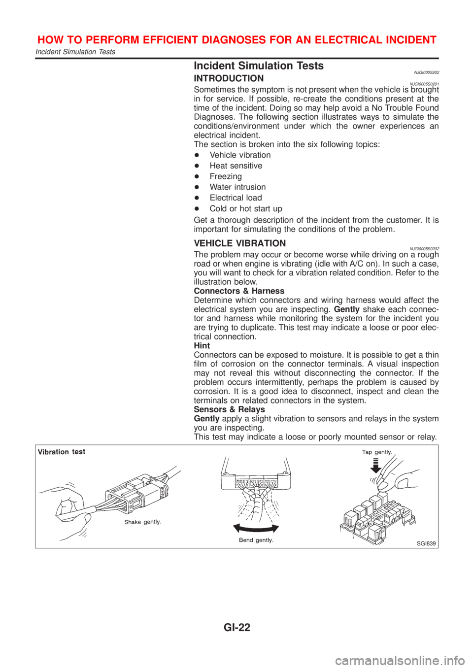
you will want to check for a vibration related condition. Refer to the
illustration below.
Connectors & Harness
Determine which connectors and wiring harness would affect the
electrical system you are inspecting.Gentlyshake each connec-
tor and harness while monitoring the system for the incident you
are trying to duplicate. This test may indicate a loose or poor elec-
trical connection.
Hint
Connectors can be exposed to moisture. It is possible to get a thin
film of corrosion on the connector terminals. A visual inspection
may not reveal this without disconnecting the connector. If the
problem occurs intermittently, perhaps the problem is caused by
corrosion. It is a good idea to disconnect, inspect and clean the
terminals on related connectors in the system.
Sensors & Relays
Gentlyapply a slight vibration to sensors and relays in the system
you are inspecting.
This test may indicate a loose or poorly mounted sensor or relay.
SGI839
HOW TO PERFORM EFFICIENT DIAGNOSES FOR AN ELECTRICAL INCIDENT
Incident Simulation Tests
GI-22
Page 68 of 2493

Maintenance Under Severe Driving Conditions
(Annual Driving Distance < 30,000 km/year)
=NJMA0043S03The maintenance intervals shown on the preceding pages are for normal operating conditions. If the vehicle
is mainly operated under severe driving conditions as shown below, more frequent maintenance must be per-
formed on the following items as shown in the table.
A Ð Driving under dusty conditions
B Ð Driving repeatedly short distances
C Ð Towing a trailer or caravan
D Ð Extensive idling
E Ð Driving in extremely adverse weather conditions or in areas where ambient temperatures are either
extremely low or extremely high
F Ð Driving in high humidity areas or in mountainous areas
G Ð Driving in areas using salt or other corrosive materials
H Ð Driving on rough and/or muddy roads or in the desert
I Ð Driving with frequent use of braking or in mountainous areas
J Ð Frequent off road use or driving in water
K Ð Sustained high speed driving
L Ð For models without Euro-OBD system
Driving conditionMaintenance
itemMaintenance
operationMaintenance interval
ABCD........Engine oil & engine oil filter
Petrol models ReplaceEvery 7,500 km (4,500 miles) or 6
months
Diesel models ReplaceEvery 10,000 km (6,000 miles) or 6
months
A...........Air cleaner filter
Petrol models ReplaceEvery 30,000 km (18,000 miles) or
24 months
Diesel models ReplaceEvery 30,000 km (18,000 miles) or
18 months
A...E.......Fuel filter
Diesel models ReplaceEvery 20,000 km (12,000 miles) or
12 months
...........LHeated Oxygen Sensor 1 (Front)
Petrol models InspectEvery 30,000 km (18,000 miles) or
24 months
...........LHeated Oxygen Sensor 2 (Rear)
Petrol models InspectEvery 30,000 km (18,000 miles) or
24 months
A...........Ventilation air filter
Petrol models ReplaceEvery 15,000 km (9,000 miles) or
12 months
Diesel models ReplaceEvery 10,000 km (6,000 miles) or 6
months
.....F......Brake fluid
Petrol models ReplaceEvery 15,000 km (9,000 miles) or
12 months
Diesel models ReplaceEvery 20,000 km (12,000 miles) or
12 months
PERIODIC MAINTENANCE (FOR EUROPE)
Maintenance Under Severe Driving Conditions (Annual Driving Distance < 30,000 km/year)
MA-12
Page 74 of 2493

Maintenance Under Severe Driving Conditions
(Annual Driving Distance > 30,000 km/year)
=NJMA0043S06The maintenance intervals shown on the preceding pages are for normal operating conditions. If the vehicle
is mainly operated under severe driving conditions as shown below, more frequent maintenance must be per-
formed on the following items as shown in the table.
A Ð Driving under dusty conditions
B Ð Driving repeatedly short distances
C Ð Towing a trailer or caravan
D Ð Extensive idling
E Ð Driving in extremely adverse weather conditions or in areas where ambient temperatures are either
extremely low or extremely high
F Ð Driving in high humidity areas or in mountainous areas
G Ð Driving in areas using salt or other corrosive materials
H Ð Driving on rough and/or muddy roads or in the desert
I Ð Driving with frequent use of braking or in mountainous areas
J Ð Frequent off road use or driving in water
K Ð Sustained high speed driving
L Ð For models without Euro-OBD system
Driving conditionMaintenance
itemMaintenance
operationMaintenance interval
ABCD........Engine oil & engine oil filter
Petrol models Replace Every 7,500 km (4,500 miles)
Diesel models Replace Every 10,000 km (6,000 miles)
A...........Air cleaner filter
Petrol models Replace Every 30,000 km (18,000 miles)
Diesel models Replace Every 30,000 km (18,000 miles)
A...E.......Fuel filter
Diesel models Replace Every 30,000 km (18,000 miles)
...........LHeated Oxygen Sensor 1 (Front)
Petrol models Inspect Every 60,000 km (36,000 miles)
...........LHeated Oxygen Sensor 2 (Rear)
Petrol models Inspect Every 60,000 km (36,000 miles)
A...........Ventilation air filter
Petrol models Replace Every 15,000 km (9,000 miles)
Diesel models Replace Every 10,000 km (6,000 miles)
.....F......Brake fluid
Petrol models Replace Every 30,000 km (18,000 miles)
Diesel models Replace Every 30,000 km (18,000 miles)
..C....H....Automatic transaxle fluid
Petrol models Replace Every 60,000 km (36,000 miles)
A.C...GHI...Brake pads, rotors & other brake system components
Petrol models Inspect Every 15,000 km (9,000 miles)
Diesel models Inspect Every 10,000 km (6,000 miles)
PERIODIC MAINTENANCE (FOR EUROPE)
Maintenance Under Severe Driving Conditions (Annual Driving Distance > 30,000 km/year)
MA-18
Page 89 of 2493

Removal and InstallationNJEM0006
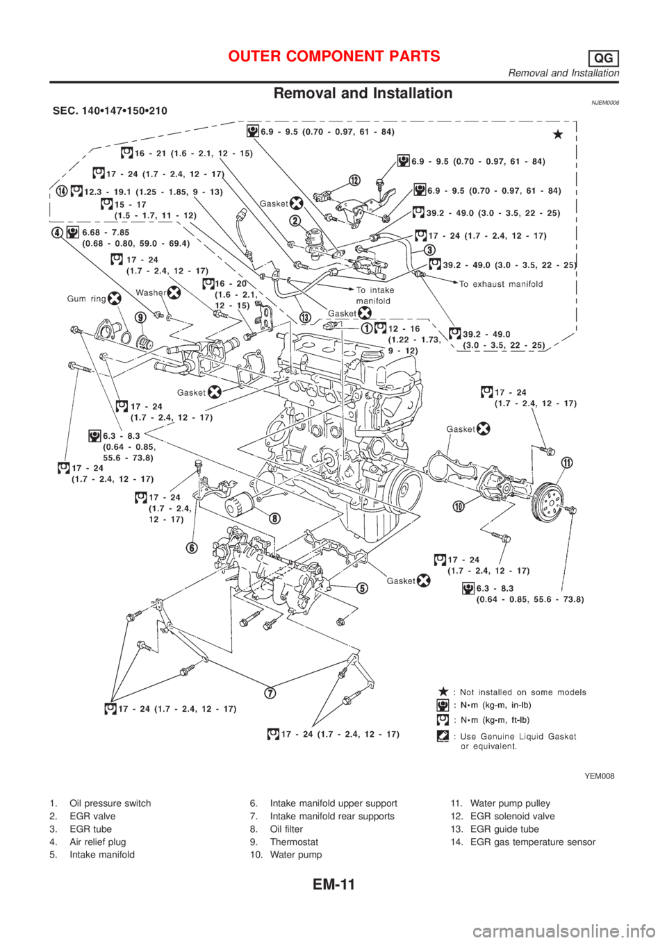
YEM008
1. Oil pressure switch
2. EGR valve
3. EGR tube
4. Air relief plug
5. Intake manifold6. Intake manifold upper support
7. Intake manifold rear supports
8. Oil filter
9. Thermostat
10. Water pump11. Water pump pulley
12. EGR solenoid valve
13. EGR guide tube
14. EGR gas temperature sensor
OUTER COMPONENT PARTSQG
Removal and Installation
EM-11
Page 91 of 2493

YEM021
1. Crankshaft pulley
2. Engine coolant temperature sen-
sor
3. Gasket
4. Exhaust manifold5. Exhaust manifold cover
6. Thermal transmitter
7. Water drain plug
8. Heated oxygen sensor 1 (front)
9. Three way catalyst10. Converter cap
11. Converter cover
12. Ignition coil
13. Spark plug
OUTER COMPONENT PARTSQG
Removal and Installation (Cont'd)
EM-13
Page 126 of 2493

SEM887F
10. Install cylinder head front cover.
+Apply liquid gasket to cylinder head front cover.
+Use Genuine Liquid Gasket or equivalent.
SEM889F
11. Install camshaft position sensor (PHASE).
SEM888F
12. Before installing rocker cover, apply a continuous bead of liq-
uid gasket to mating surface of cylinder head.
SEM105G
13. Install rocker cover with rocker cover gasket and tighten bolts
in numerical order as shown in the figure.
14. Install spark plugs.
15. Install ignition coils.
16. Install exhaust manifold.
17. Install intake manifold rear supports.
18. Connect vacuum hoses, fuel hoses, water hose, wire, harness,
connectors and so on.
19. Install front exhaust tube.
20. Install front undercovers.
21. Install air duct to intake manifold collector.
22. Drive belts.
For adjusting drive belt deflection, refer to ªCheckingº, EM-15.
23. Reinstall parts in reverse order of removal.
CYLINDER HEADQG
Installation (Cont'd)
EM-48
Page 312 of 2493

Supplemental Restraint System (SRS) ªAIR
BAGº and ªSEAT BELT PRE-TENSIONERº
NJEC0002The Supplemental Restraint System such as ªAIR BAGº and ªSEAT BELT PRE-TENSIONERº used along with
a seat belt, helps to reduce the risk or severity of injury to the driver and front passenger for certain types of
collision. The SRS system composition which is available to NISSAN MODEL N16 is as follows (The compo-
sition varies according to the destination and optional equipment.):
+For a frontal collision
The Supplemental Restraint System consists of driver air bag module (located in the center of the steer-
ing wheel), front passenger air bag module (located on the instrument panel on passenger side), front seat
belt pre-tensioners, a diagnoses sensor unit, warning lamp, wiring harness and spiral cable.
+For a side collision
The Supplemental Restraint System consists of front side air bag module (located in the outer side of front
seat), side air bag (satellite) sensor, diagnoses sensor unit (one of components of air bags for a frontal
collision), wiring harness, warning lamp (one of components of air bags for a frontal collision).
Information necessary to service the system safely is included in theRS sectionof this Service Manual.
WARNING:
+To avoid rendering the SRS inoperative, which could increase the risk of personal injury or death
in the event of a collision which would result in air bag inflation, all maintenance should be per-
formed by an authorized NISSAN dealer.
+Improper maintenance, including incorrect removal and installation of the SRS, can lead to per-
sonal injury caused by unintentional activation of the system. For removal of Spiral Cable and Air
Bag Module, see the RS section.
+Do not use electrical test equipment on any circuit related to the SRS unless instructed to in this
Service Manual. SRS wiring harness can be identified by yellow harness connector.
Precautions for On Board Diagnostic (OBD)
System of Engine and A/T
NJEC0003The ECM has an on board diagnostic system. It will light up the malfunction indicator (MI) to warn the driver
of a malfunction causing emission deterioration.
CAUTION:
+Be sure to turn the ignition switch ªOFFº and disconnect the negative battery terminal before any
repair or inspection work. The open/short circuit of related switches, sensors, solenoid valves, etc.
will cause the MI to light up.
+Be sure to connect and lock the connectors securely after work. A loose (unlocked) connector will
cause the MI to light up due to the open circuit. (Be sure the connector is free from water, grease,
dirt, bent terminals, etc.)
+Certain systems and components, especially those related to OBD, may use a new style slide-
locking type harness connector.
For description and how to disconnect, refer to EL section, ªDescriptionº, ªHARNESS CONNEC-
TORº.
+Be sure to route and secure the harnesses properly after work. The interference of the harness with
a bracket, etc. may cause the MI to light up due to the short circuit.
+Be sure to connect rubber tubes properly after work. A misconnected or disconnected rubber tube
may cause the MI to light up due to the malfunction of fuel injection system, etc.
+Be sure to erase the unnecessary malfunction information (repairs completed) from the ECM and
TCM (Transmission Control Module) before returning the vehicle to the customer.
PRECAUTIONSQG
Supplemental Restraint System (SRS) ªAIR BAGº and ªSEAT BELT PRE-TENSIONERº
EC-16
Page 421 of 2493

SYMPTOM
Reference
page
HARD/NO START/RESTART (EXCP. HA)
ENGINE STALL
HESITATION/SURGING/FLAT SPOT
SPARK KNOCK/DETONATION
LACK OF POWER/POOR ACCELERATION
HIGH IDLE/LOW IDLE
ROUGH IDLE/HUNTING
IDLING VIBRATION
SLOW/NO RETURN TO IDLE
OVERHEATS/WATER TEMPERATURE HIGH
EXCESSIVE FUEL CONSUMPTION
EXCESSIVE OIL CONSUMPTION
BATTERY DEAD (UNDER CHARGE)
Warranty symptom code AA AB AC AD AE AF AG AH AJ AK AL AM HA
Crankshaft position sensor (POS)
circuit22EC-272
Camshaft position sensor
(PHASE) circuit3 2 3 EC-278
Mass air flow sensor circuit11222 22 2EC-152
Heated oxygen sensor 1 (front)
circuit1232 22 2EC-176,
183
Engine coolant temperature sen-
sor circuit112323223 2EC-163,
165
Throttle position sensor circuit 1 222222 2EC-168
Incorrect throttle position sensor
adjustment31 11111 1EC-98
Vehicle speed sensor circuit 2 3 3 3 EC-309
Knock sensor circuit 2 3 EC-268
ECM 22333333333EC-327,
123
Start signal circuit 2EC-461
PNP switch circuit 3 3 3 3 3 EC-364
Power steering oil pressure switch
circuit2 3 3 EC-471
Electrical load signal circuit 3 3 EC-480
1 - 6: The numbers refer to the order of inspection.
(continued on next page)
TROUBLE DIAGNOSIS Ð GENERAL DESCRIPTIONQG
Symptom Matrix Chart (Cont'd)
EC-125