2001 NISSAN ALMERA N16 key battery
[x] Cancel search: key batteryPage 3 of 2493

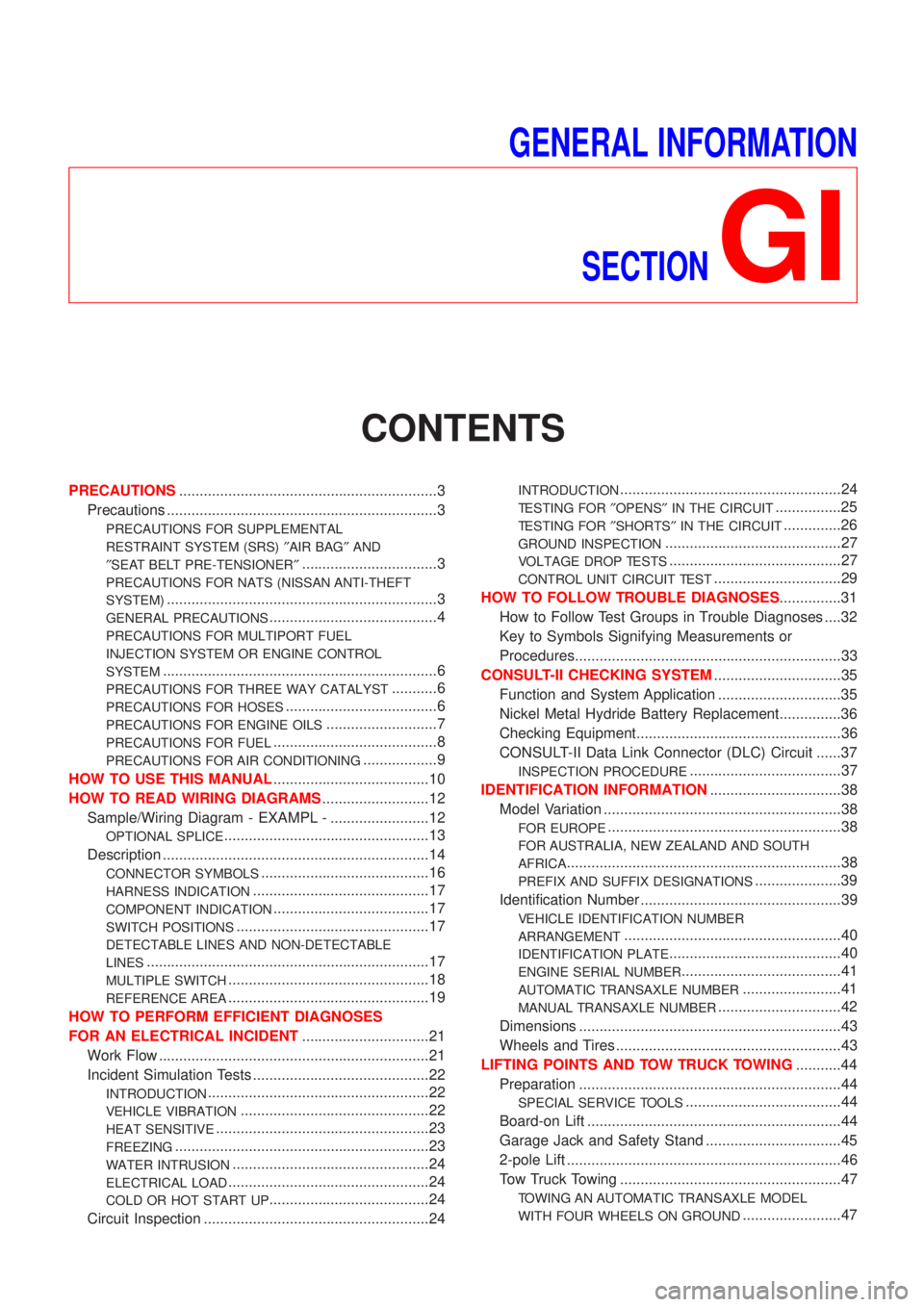
GENERAL INFORMATION
SECTION
GI
CONTENTS
PRECAUTIONS...............................................................3
Precautions ..................................................................3
PRECAUTIONS FOR SUPPLEMENTAL
RESTRAINT SYSTEM (SRS)²AIR BAG²AND
²SEAT BELT PRE-TENSIONER²
.................................3
PRECAUTIONS FOR NATS (NISSAN ANTI-THEFT
SYSTEM)
..................................................................3
GENERAL PRECAUTIONS.........................................4
PRECAUTIONS FOR MULTIPORT FUEL
INJECTION SYSTEM OR ENGINE CONTROL
SYSTEM
...................................................................6
PRECAUTIONS FOR THREE WAY CATALYST...........6
PRECAUTIONS FOR HOSES.....................................6
PRECAUTIONS FOR ENGINE OILS...........................7
PRECAUTIONS FOR FUEL........................................8
PRECAUTIONS FOR AIR CONDITIONING..................9
HOW TO USE THIS MANUAL......................................10
HOW TO READ WIRING DIAGRAMS..........................12
Sample/Wiring Diagram - EXAMPL - ........................12
OPTIONAL SPLICE..................................................13
Description .................................................................14
CONNECTOR SYMBOLS.........................................16
HARNESS INDICATION...........................................17
COMPONENT INDICATION......................................17
SWITCH POSITIONS...............................................17
DETECTABLE LINES AND NON-DETECTABLE
LINES
.....................................................................17
MULTIPLE SWITCH.................................................18
REFERENCE AREA.................................................19
HOW TO PERFORM EFFICIENT DIAGNOSES
FOR AN ELECTRICAL INCIDENT...............................21
Work Flow ..................................................................21
Incident Simulation Tests ...........................................22
INTRODUCTION......................................................22
VEHICLE VIBRATION..............................................22
HEAT SENSITIVE....................................................23
FREEZING..............................................................23
WATER INTRUSION................................................24
ELECTRICAL LOAD.................................................24
COLD OR HOT START UP.......................................24
Circuit Inspection .......................................................24
INTRODUCTION......................................................24
TESTING FOR²OPENS²IN THE CIRCUIT................25
TESTING FOR²SHORTS²IN THE CIRCUIT..............26
GROUND INSPECTION...........................................27
VOLTAGE DROP TESTS..........................................27
CONTROL UNIT CIRCUIT TEST...............................29
HOW TO FOLLOW TROUBLE DIAGNOSES...............31
How to Follow Test Groups in Trouble Diagnoses ....32
Key to Symbols Signifying Measurements or
Procedures.................................................................33
CONSULT-II CHECKING SYSTEM...............................35
Function and System Application ..............................35
Nickel Metal Hydride Battery Replacement...............36
Checking Equipment..................................................36
CONSULT-II Data Link Connector (DLC) Circuit ......37
INSPECTION PROCEDURE.....................................37
IDENTIFICATION INFORMATION................................38
Model Variation ..........................................................38
FOR EUROPE.........................................................38
FOR AUSTRALIA, NEW ZEALAND AND SOUTH
AFRICA
...................................................................38
PREFIX AND SUFFIX DESIGNATIONS.....................39
Identification Number .................................................39
VEHICLE IDENTIFICATION NUMBER
ARRANGEMENT
.....................................................40
IDENTIFICATION PLATE..........................................40
ENGINE SERIAL NUMBER.......................................41
AUTOMATIC TRANSAXLE NUMBER........................41
MANUAL TRANSAXLE NUMBER..............................42
Dimensions ................................................................43
Wheels and Tires .......................................................43
LIFTING POINTS AND TOW TRUCK TOWING...........44
Preparation ................................................................44
SPECIAL SERVICE TOOLS......................................44
Board-on Lift ..............................................................44
Garage Jack and Safety Stand .................................45
2-pole Lift ...................................................................46
Tow Truck Towing ......................................................47
TOWING AN AUTOMATIC TRANSAXLE MODEL
WITH FOUR WHEELS ON GROUND
........................47
Page 7 of 2493

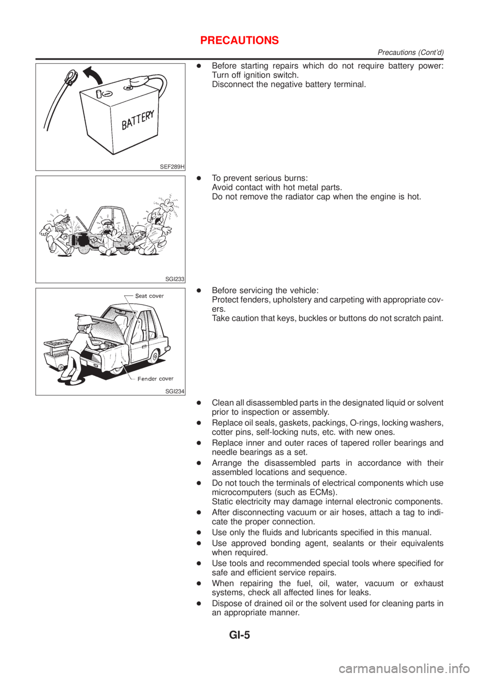
SEF289H
+Before starting repairs which do not require battery power:
Turn off ignition switch.
Disconnect the negative battery terminal.
SGI233
+To prevent serious burns:
Avoid contact with hot metal parts.
Do not remove the radiator cap when the engine is hot.
SGI234
+Before servicing the vehicle:
Protect fenders, upholstery and carpeting with appropriate cov-
ers.
Take caution that keys, buckles or buttons do not scratch paint.
+Clean all disassembled parts in the designated liquid or solvent
prior to inspection or assembly.
+Replace oil seals, gaskets, packings, O-rings, locking washers,
cotter pins, self-locking nuts, etc. with new ones.
+Replace inner and outer races of tapered roller bearings and
needle bearings as a set.
+Arrange the disassembled parts in accordance with their
assembled locations and sequence.
+Do not touch the terminals of electrical components which use
microcomputers (such as ECMs).
Static electricity may damage internal electronic components.
+After disconnecting vacuum or air hoses, attach a tag to indi-
cate the proper connection.
+Use only the fluids and lubricants specified in this manual.
+Use approved bonding agent, sealants or their equivalents
when required.
+Use tools and recommended special tools where specified for
safe and efficient service repairs.
+When repairing the fuel, oil, water, vacuum or exhaust
systems, check all affected lines for leaks.
+Dispose of drained oil or the solvent used for cleaning parts in
an appropriate manner.
PRECAUTIONS
Precautions (Cont'd)
GI-5
Page 28 of 2493

voltage; open is further down the circuit than the relay.
no voltage; open is between SW1 and relay (point B).
5) Close the relay and probe at the solenoid.
voltage; open is further down the circuit than the solenoid.
no voltage; open is between relay and solenoid (point C).
Any powered circuit can be diagnosed using the approach in the
above example.
TESTING FOR ªSHORTSº IN THE CIRCUITNJGI0005S0303To simplify the discussion of shorts in the system please refer to
the schematic below.
SGI847
Resistance Check Method
1) Disconnect the battery negative cable and remove the blown
fuse.
2) Disconnect all loads (SW1 open, relay disconnected and sole-
noid disconnected) powered through the fuse.
3) Connect one probe of the ohmmeter to the load side of the fuse
terminal. Connect the other probe to a known good ground.
4) With SW1 open, check for continuity.
continuity; short is between fuse terminal and SW1 (point A).
no continuity; short is further down the circuit than SW1.
5) Close SW1 and disconnect the relay. Put probes at the load
side of fuse terminal and a known good ground. Then, check
for continuity.
continuity; short is between SW1 and the relay (point B).
no continuity; short is further down the circuit than the relay.
6) Close SW1 and jump the relay contacts with jumper wire. Put
probes at the load side of fuse terminal and a known good
ground. Then, check for continuity.
continuity; short is between relay and solenoid (point C).
no continuity; check solenoid, retrace steps.
Voltage Check Method
1) Remove the blown fuse and disconnect all loads (i.e. SW1
open, relay disconnected and solenoid disconnected) powered
through the fuse.
2) Turn the ignition key to the ON or START position. Verify bat-
tery voltage at the B + side of the fuse terminal (one lead on
the B + terminal side of the fuse block and one lead on a known
good ground).
3) With SW1 open and the DMM leads across both fuse
terminals, check for voltage.
voltage; short is between fuse block and SW1 (point A).
no voltage; short is further down the circuit than SW1.
4) With SW1 closed, relay and solenoid disconnected and the
DMM leads across both fuse terminals, check for voltage.
voltage; short is between SW1 and the relay (point B).
HOW TO PERFORM EFFICIENT DIAGNOSES FOR AN ELECTRICAL INCIDENT
Circuit Inspection (Cont'd)
GI-26
Page 34 of 2493

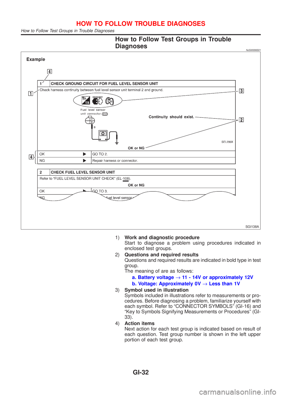
How to Follow Test Groups in Trouble
Diagnoses
NJGI0006S01
SGI138A
1)Work and diagnostic procedure
Start to diagnose a problem using procedures indicated in
enclosed test groups.
2)Questions and required results
Questions and required results are indicated in bold type in test
group.
The meaning of are as follows:
a. Battery voltage®11 - 14V or approximately 12V
b. Voltage: Approximately 0V®Less than 1V
3)Symbol used in illustration
Symbols included in illustrations refer to measurements or pro-
cedures. Before diagnosing a problem, familiarize yourself with
each symbol. Refer to ªCONNECTOR SYMBOLSº (GI-16) and
ªKey to Symbols Signifying Measurements or Proceduresº (GI-
33).
4)Action items
Next action for each test group is indicated based on result of
each question. Test group number is shown in the left upper
portion of each test group.
HOW TO FOLLOW TROUBLE DIAGNOSES
How to Follow Test Groups in Trouble Diagnoses
GI-32
Page 35 of 2493

Key to Symbols Signifying Measurements or
Procedures
NJGI0006S02
Symbol Symbol explanation Symbol Symbol explanation
Check after disconnecting the con-
nector to be measured.Procedure with Generic Scan Tool
(GST, OBD-II scan tool)
Check after connecting the connec-
tor to be measured.Procedure without CONSULT-II or
GST
Insert key into ignition switch.A/C switch is ªOFFº.
Remove key from ignition switch.A/C switch is ªONº.
Turn ignition switch to ªOFFº posi-
tion.REC switch is ªONº.
Turn ignition switch to ªONº position.REC switch is ªOFFº.
Turn ignition switch to ªSTARTº posi-
tion.Fan switch is ªONº. (At any position
except for ªOFFº position)
Turn ignition switch from ªOFFº to
ªACCº position.Fan switch is ªOFFº.
Turn ignition switch from ªACCº to
ªOFFº position.Apply positive voltage from battery
with fuse directly to components.
Turn ignition switch from ªOFFº to
ªONº position.Drive vehicle.
Turn ignition switch from ªONº to
ªOFFº position.Disconnect battery negative cable.
Do not start engine, or check with
engine stopped.Depress brake pedal.
Start engine, or check with engine
running.Release brake pedal.
Apply parking brake.Depress accelerator pedal.
Release parking brake.Release accelerator pedal.
HOW TO FOLLOW TROUBLE DIAGNOSES
Key to Symbols Signifying Measurements or Procedures
GI-33
Page 58 of 2493

NJMA0036
Shown below are Pre-delivery Inspection Items required for the new vehicle. It is recommended that
necessary items other than those listed here be added, paying due regard to the conditions in each
country.
Perform applicable items on each model. Consult text of this section for specifications.
UNDER HOOD Ð engine off
Radiator coolant level and coolant hose connections for leaks
Battery fluid level, specific gravity and conditions of battery terminals
Drive belts tension
Fuel filter for water or dusts (Diesel only), and fuel lines and connections for leaks
Engine oil level and oil leaks
Clutch and brake reservoir fluid level and fluid lines for leaks
Windshield and rear window washer and headlamp cleaner reservoir fluid level
Power steering reservoir fluid level and hose connections for leaks
ON INSIDE AND OUTSIDE
Remove front spring/strut spacer (If applicable)
Operation of all instruments, gauges, lights and accessories
Operation of horn(s), wiper and washer
Steering lock for operation
Check air conditioner for gas leaks
Front and rear seats, and seat belts for operation
All moldings, trims and fittings for fit and alignment
All windows for operation and alignment
Hood, trunk lid, door panels for fit and alignment
Latches, keys and locks for operation
Weatherstrips for adhesion and fit
Headlamp aiming
Tighten wheel nuts (Inc. inner nuts if applicable)
Tire pressure (Inc. spare tire)
Check front wheels for toe-in
Install clock/voltmeter/room lamp fuse (If applicable)
Install deodorizing filter to air conditioner (If applicable)
Remove wiper blade protectors (If applicable)
UNDER BODY
Manual transmission/transaxle, transfer and differential gear oil level
Brake and fuel lines and oil/fluid reservoirs for leaks
Tighten bolts and nuts of steering linkage and gear box, suspension, propeller shafts and drive shafts
Tighten rear body bolts and nuts (Models with wooden bed only)
ROAD TEST
Clutch operation
Parking brake operation
Service brake operation
Automatic transmission/transaxle shift timing and kickdown
Steering control and returnability
Engine performance
Squeaks and rattles
ENGINE OPERATING AND HOT
Adjust idle speed
Automatic transmission/transaxle fluid level
Engine idling and stop knob operation (Diesel only)
FINAL INSPECTION
Install necessary parts (outside mirror, wheel covers, seat belts, mat, carpet or mud flaps)
Inspect for interior and exterior metal and paint damage
Check for spare tire, jack, tools (wheel chock), and literature
Wash, clean interior and exterior
: Not applicable to this model
PRE-DELIVERY INSPECTION ITEMS
MA-2
Page 1523 of 2493

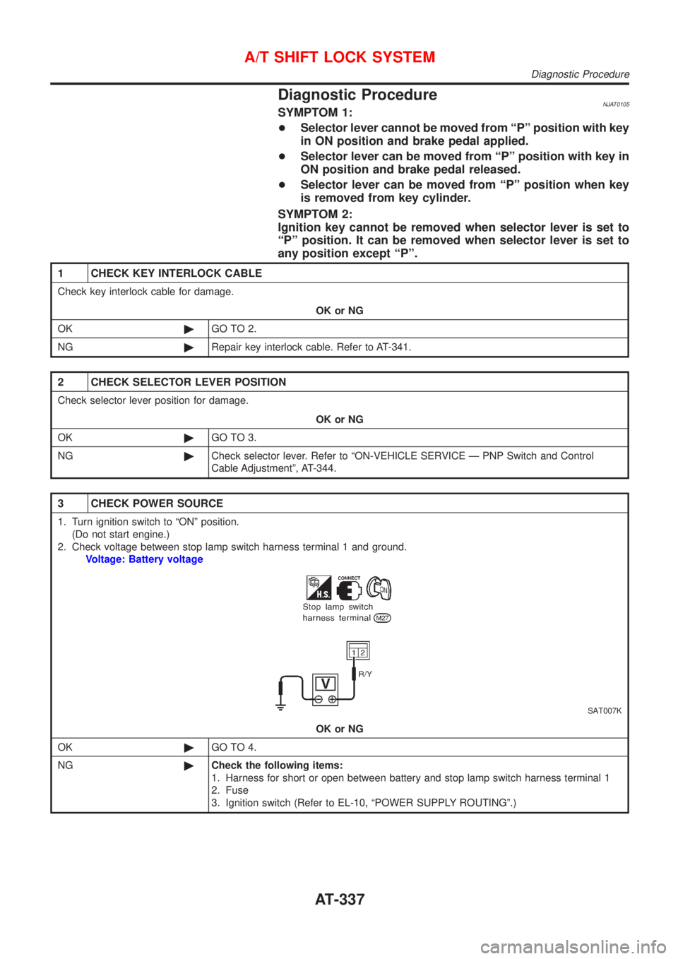
Diagnostic ProcedureNJAT0105SYMPTOM 1:
+Selector lever cannot be moved from ªPº position with key
in ON position and brake pedal applied.
+Selector lever can be moved from ªPº position with key in
ON position and brake pedal released.
+Selector lever can be moved from ªPº position when key
is removed from key cylinder.
SYMPTOM 2:
Ignition key cannot be removed when selector lever is set to
ªPº position. It can be removed when selector lever is set to
any position except ªPº.
1 CHECK KEY INTERLOCK CABLE
Check key interlock cable for damage.
OK or NG
OK©GO TO 2.
NG©Repair key interlock cable. Refer to AT-341.
2 CHECK SELECTOR LEVER POSITION
Check selector lever position for damage.
OK or NG
OK©GO TO 3.
NG©Check selector lever. Refer to ªON-VEHICLE SERVICE Ð PNP Switch and Control
Cable Adjustmentº, AT-344.
3 CHECK POWER SOURCE
1. Turn ignition switch to ªONº position.
(Do not start engine.)
2. Check voltage between stop lamp switch harness terminal 1 and ground.
Voltage: Battery voltage
SAT007K
OK or NG
OK©GO TO 4.
NG©Check the following items:
1. Harness for short or open between battery and stop lamp switch harness terminal 1
2. Fuse
3. Ignition switch (Refer to EL-10, ªPOWER SUPPLY ROUTINGº.)
A/T SHIFT LOCK SYSTEM
Diagnostic Procedure
AT-337
Page 1871 of 2493
![NISSAN ALMERA N16 2001 Electronic Repair Manual SRS772
7. Diagnostic codes are displayed on ªSELF-DIAG [CURRENT]º.
SRS701
If no malfunction is detected on ªSELF-DIAG [CURRENT]º but mal-
function is indicated by the ªAIR BAGº warning lamp, go NISSAN ALMERA N16 2001 Electronic Repair Manual SRS772
7. Diagnostic codes are displayed on ªSELF-DIAG [CURRENT]º.
SRS701
If no malfunction is detected on ªSELF-DIAG [CURRENT]º but mal-
function is indicated by the ªAIR BAGº warning lamp, go](/manual-img/5/57351/w960_57351-1870.png)
SRS772
7. Diagnostic codes are displayed on ªSELF-DIAG [CURRENT]º.
SRS701
If no malfunction is detected on ªSELF-DIAG [CURRENT]º but mal-
function is indicated by the ªAIR BAGº warning lamp, go to DIAG-
NOSTIC PROCEDURE 4, page RS-56, to diagnose the following
situations:
+Self-diagnostic result ªSELF-DIAG [PAST]º (previously stored
in the memory) might not be erased after repair.
+The SRS system malfunctions intermittently.
8. Touch ªPRINTº.
9. Compare diagnostic codes to ªCONSULT-II Diagnostic Code
Chartº, RS-51.
10. Touch ªBACKº key of CONSULT-II until ªSELECT SYSTEMº
appears in order to return to User mode from Diagnosis mode.
11. Turn ignition switch ªOFFº, then turn off and disconnect
CONSULT-II, and disconnect both battery cables.
12. Repair the system as outlined by the ªRepair orderº in ªCON-
SULT-II Diagnostic Code Chartº, that corresponds to the self-
diagnostic result. For replacement procedure of component
parts, refer to RS-26.
13. After repairing the system, go to DIAGNOSTIC PROCEDURE
3, page RS-54 for final checking.
CONSULT-II DIAGNOSTIC CODE CHART (ªSELF-DIAG
[CURRENT]º)
NJRS0048S0102
Diagnostic item ExplanationRepair order
Recheck SRS at each
replacement.
NO DTC IS DETECTED When malfunction is indicated
by the ªAIR BAGº warning
lamp in User mode+Self-diagnostic result ªSELF-
DIAG [PAST]º (previously
stored in the memory) might
not be erased after repair.
+Intermittent malfunction has
been detected in the past.+Go to DIAGNOSTIC PRO-
CEDURE 3 (RS-54).
+No malfunction is detected.+Go to DIAGNOSTIC PRO-
CEDURE 3 (RS-54).
SUPPLEMENTAL RESTRAINT SYSTEM (SRS)
Trouble Diagnoses with CONSULT-II (Cont'd)
RS-51