2001 NISSAN ALMERA N16 wheel alignment
[x] Cancel search: wheel alignmentPage 58 of 2493

NJMA0036
Shown below are Pre-delivery Inspection Items required for the new vehicle. It is recommended that
necessary items other than those listed here be added, paying due regard to the conditions in each
country.
Perform applicable items on each model. Consult text of this section for specifications.
UNDER HOOD Ð engine off
Radiator coolant level and coolant hose connections for leaks
Battery fluid level, specific gravity and conditions of battery terminals
Drive belts tension
Fuel filter for water or dusts (Diesel only), and fuel lines and connections for leaks
Engine oil level and oil leaks
Clutch and brake reservoir fluid level and fluid lines for leaks
Windshield and rear window washer and headlamp cleaner reservoir fluid level
Power steering reservoir fluid level and hose connections for leaks
ON INSIDE AND OUTSIDE
Remove front spring/strut spacer (If applicable)
Operation of all instruments, gauges, lights and accessories
Operation of horn(s), wiper and washer
Steering lock for operation
Check air conditioner for gas leaks
Front and rear seats, and seat belts for operation
All moldings, trims and fittings for fit and alignment
All windows for operation and alignment
Hood, trunk lid, door panels for fit and alignment
Latches, keys and locks for operation
Weatherstrips for adhesion and fit
Headlamp aiming
Tighten wheel nuts (Inc. inner nuts if applicable)
Tire pressure (Inc. spare tire)
Check front wheels for toe-in
Install clock/voltmeter/room lamp fuse (If applicable)
Install deodorizing filter to air conditioner (If applicable)
Remove wiper blade protectors (If applicable)
UNDER BODY
Manual transmission/transaxle, transfer and differential gear oil level
Brake and fuel lines and oil/fluid reservoirs for leaks
Tighten bolts and nuts of steering linkage and gear box, suspension, propeller shafts and drive shafts
Tighten rear body bolts and nuts (Models with wooden bed only)
ROAD TEST
Clutch operation
Parking brake operation
Service brake operation
Automatic transmission/transaxle shift timing and kickdown
Steering control and returnability
Engine performance
Squeaks and rattles
ENGINE OPERATING AND HOT
Adjust idle speed
Automatic transmission/transaxle fluid level
Engine idling and stop knob operation (Diesel only)
FINAL INSPECTION
Install necessary parts (outside mirror, wheel covers, seat belts, mat, carpet or mud flaps)
Inspect for interior and exterior metal and paint damage
Check for spare tire, jack, tools (wheel chock), and literature
Wash, clean interior and exterior
: Not applicable to this model
PRE-DELIVERY INSPECTION ITEMS
MA-2
Page 62 of 2493

Chassis and Body MaintenanceNJMA0005S05Abbreviations: I = Inspect and correct or replace as necessary, R = Replace, L = Lubricate.
MAINTENANCE OPERATIONMAINTENANCE INTERVAL
Reference page Perform either at number of kilome-
ters (miles) or months, whichever
comes first.km x 1,000
(Miles x 1,000)
Months1
(0.6)
Ð10
(6)
620
(12)
1230
(18)
1840
(24)
2450
(30)
3060
(36)
3670
(42)
4280
(48)
48
Underhood and under vehicle
Brake, clutch & automatic transaxle
fluid (For level & leaks)HIIIIIIIIBR-7, AT-78
Brake fluidHR R BR-18
Brake booster vacuum hoses, con-
nections & check valveI I BR-22
Power steering fluid & lines (For
level & leaks)I*1 I I*1 I I*1 I I*1 I ST-7
Brake, clutch & exhaust systemsIIIIIIIIBR-7, FE-11,
FE-27
Manual transaxle gear oil (For level
& leaks)I*1 I I*1 I I*1 I I*1 I MT-15, MT-14
Steering gear & linkage, axle & sus-
pension parts & drive shaftsHI*2IIIIST-7,SU-6, SU-7
Outside and inside
Wheel alignment (If necessary,
rotate & balance wheels)IIIISU-7, SU-14
Brake pads, rotors & other brake
componentsHIIIIIIIIBR-27, BR-35
Brake linings, drums & other brake
componentsHIIIIBR-33
Lock, hinges & hood latchHL*1 L L*1 L L*1 L L*1 L BT-7, BT-16
Seat belts, buckles, retractors,
anchors & adjusterIIIIRS-4
Foot brake, parking brake & clutch
(For free play, stroke & operation)I*1 I I*1 I I*1 I I*1 IBR-12, BR-47,
CL-5
Ventilation air filterHReplace every 12,000 km (7,500 miles) or 12 months HA-102
Supplemental air bag systems See NOTE (1) RS-25
NOTE:
(1) Inspect at the first 10 years, and then every 2 years.
HMaintenance items with ªHº should be performed more frequently according to ªMaintenance Under Severe Driving Con-
ditionsº.
*1: Models except for Australia
*2: Models without three way catalyst
PERIODIC MAINTENANCE (EXCEPT FOR EUROPE)
Chassis and Body Maintenance
MA-6
Page 1030 of 2493
NJCL0004
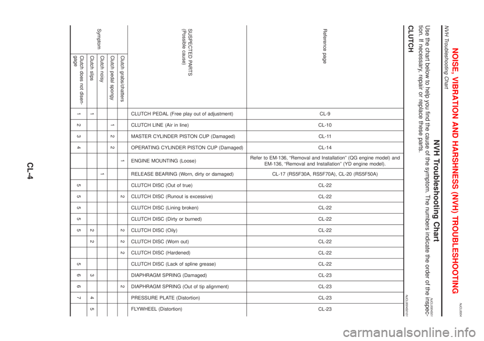
NVH Troubleshooting ChartNJCL0004S01Use the chart below to help you find the cause of the symptom. The numbers indicate the order of the inspec-
tion. If necessary, repair or replace these parts.
CLUTCHNJCL0004S0101
Reference pageCL-9
CL-10
CL-11
CL-14
Refer to EM-136, ªRemoval and Installationº (QG engine model) and
EM-136, ªRemoval and Installationº (YD engine model).
CL-17 (RS5F30A, RS5F70A), CL-20 (RS5F50A)
CL-22
CL-22
CL-22
CL-22
CL-22
CL-22
CL-22
CL-22
CL-23
CL-23
CL-23
CL-23
SUSPECTED PARTS
(Possible cause)
CLUTCH PEDAL (Free play out of adjustment)
CLUTCH LINE (Air in line)
MASTER CYLINDER PISTON CUP (Damaged)
OPERATING CYLINDER PISTON CUP (Damaged)
ENGINE MOUNTING (Loose)
RELEASE BEARING (Worn, dirty or damaged)
CLUTCH DISC (Out of true)
CLUTCH DISC (Runout is excessive)
CLUTCH DISC (Lining broken)
CLUTCH DISC (Dirty or burned)
CLUTCH DISC (Oily)
CLUTCH DISC (Worn out)
CLUTCH DISC (Hardened)
CLUTCH DISC (Lack of spline grease)
DIAPHRAGM SPRING (Damaged)
DIAPHRAGM SPRING (Out of tip alignment)
PRESSURE PLATE (Distortion)
FLYWHEEL (Distortion)
SymptomClutch grabs/chatters 1 2 2 2 2 2
Clutch pedal spongy 1 2 2
Clutch noisy 1
Clutch slips 1 2 2 3 4 5
Clutch does not disen-
gage1234 55555 5667
NOISE, VIBRATION AND HARSHNESS (NVH) TROUBLESHOOTING
NVH Troubleshooting Chart
CL-4
Page 1646 of 2493
SBR686C
Precautions
PRECAUTIONSNJAX0001+When installing rubber parts, final tightening must be car-
ried out under unladen condition* with tires on ground.
*: Fuel, radiator coolant and engine oil full. Spare tire, jack,
hand tools and mats in designated positions.
+After installing removed suspension parts, check wheel
alignment and adjust if necessary.
+Use flare nut wrench when removing or installing brake
tubes.
+Always torque brake lines when installing.
Preparation
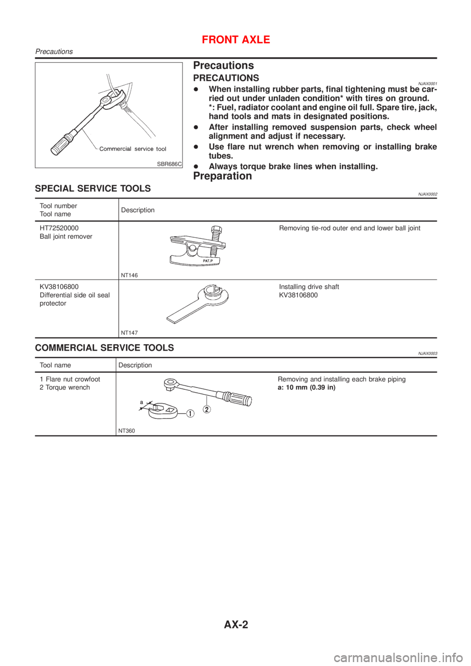
SPECIAL SERVICE TOOLSNJAX0002
Tool number
Tool nameDescription
HT72520000
Ball joint remover
NT146
Removing tie-rod outer end and lower ball joint
KV38106800
Differential side oil seal
protector
NT147
Installing drive shaft
KV38106800
COMMERCIAL SERVICE TOOLSNJAX0003
Tool name Description
1 Flare nut crowfoot
2 Torque wrench
NT360
Removing and installing each brake piping
a: 10 mm (0.39 in)
FRONT AXLE
Precautions
AX-2
Page 1666 of 2493
SBR686C
Precautions
PRECAUTIONSNJAX0022+When installing each rubber part, final tightening must be
carried out under unladen condition* with tires on ground.
*: Fuel, radiator coolant and engine oil full. Spare tire, jack,
hand tools and mats in designated positions.
+Use flare nut wrench when removing or installing brake
tubes.
+After installing removed suspension parts, check wheel
alignment.
+Do not jack up at the trailing arm and lateral link.
+Always torque brake lines when installing.
Preparation
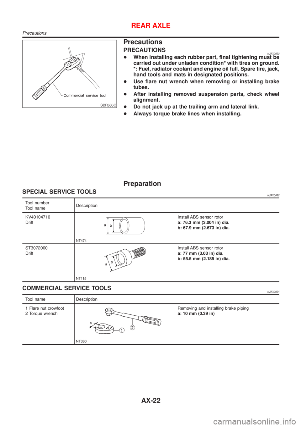
SPECIAL SERVICE TOOLSNJAX0032
Tool number
Tool nameDescription
KV40104710
Drift
NT474
Install ABS sensor rotor
a: 76.3 mm (3.004 in) dia.
b: 67.9 mm (2.673 in) dia.
ST3072000
Drift
NT115
Install ABS sensor rotor
a: 77 mm (3.03 in) dia.
b: 55.5 mm (2.185 in) dia.
COMMERCIAL SERVICE TOOLSNJAX0024
Tool name Description
1 Flare nut crowfoot
2 Torque wrench
NT360
Removing and installing brake piping
a: 10 mm (0.39 in)
REAR AXLE
Precautions
AX-22
Page 1673 of 2493
FRONT & REAR SUSPENSION
SECTION
SU
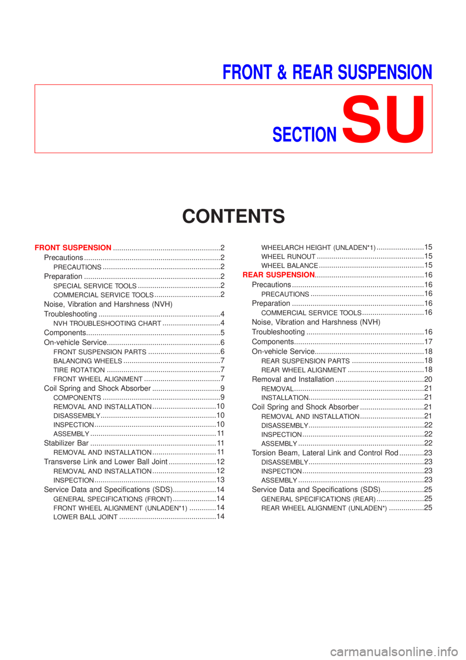
CONTENTS
FRONT SUSPENSION....................................................2
Precautions ..................................................................2
PRECAUTIONS.........................................................2
Preparation ..................................................................2
SPECIAL SERVICE TOOLS........................................2
COMMERCIAL SERVICE TOOLS................................2
Noise, Vibration and Harshness (NVH)
Troubleshooting ...........................................................4
NVH TROUBLESHOOTING CHART............................4
Components.................................................................5
On-vehicle Service.......................................................6
FRONT SUSPENSION PARTS...................................6
BALANCING WHEELS...............................................7
TIRE ROTATION.......................................................7
FRONT WHEEL ALIGNMENT.....................................7
Coil Spring and Shock Absorber .................................9
COMPONENTS.........................................................9
REMOVAL AND INSTALLATION...............................10
DISASSEMBLY........................................................10
INSPECTION...........................................................10
ASSEMBLY............................................................. 11
Stabilizer Bar ............................................................. 11
REMOVAL AND INSTALLATION............................... 11
Transverse Link and Lower Ball Joint .......................12
REMOVAL AND INSTALLATION...............................12
INSPECTION...........................................................13
Service Data and Specifications (SDS).....................14
GENERAL SPECIFICATIONS (FRONT).....................14
FRONT WHEEL ALIGNMENT (UNLADEN*1).............14
LOWER BALL JOINT...............................................14
WHEELARCH HEIGHT (UNLADEN*1).......................15
WHEEL RUNOUT....................................................15
WHEEL BALANCE...................................................15
REAR SUSPENSION.....................................................16
Precautions ................................................................16
PRECAUTIONS.......................................................16
Preparation ................................................................16
COMMERCIAL SERVICE TOOLS..............................16
Noise, Vibration and Harshness (NVH)
Troubleshooting .........................................................16
Components...............................................................17
On-vehicle Service.....................................................18
REAR SUSPENSION PARTS...................................18
REAR WHEEL ALIGNMENT.....................................18
Removal and Installation ...........................................20
REMOVAL...............................................................21
INSTALLATION........................................................21
Coil Spring and Shock Absorber ...............................21
REMOVAL AND INSTALLATION...............................21
DISASSEMBLY........................................................22
INSPECTION...........................................................22
ASSEMBLY.............................................................22
Torsion Beam, Lateral Link and Control Rod ............23
DISASSEMBLY........................................................23
INSPECTION...........................................................23
ASSEMBLY.............................................................23
Service Data and Specifications (SDS).....................25
GENERAL SPECIFICATIONS (REAR).......................25
REAR WHEEL ALIGNMENT (UNLADEN*).................25
Page 1674 of 2493
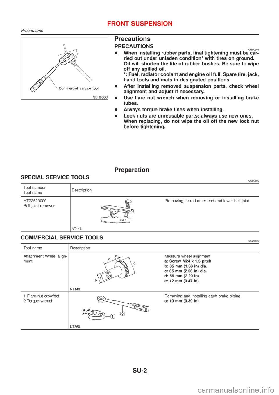
SBR686C
Precautions
PRECAUTIONSNJSU0001+When installing rubber parts, final tightening must be car-
ried out under unladen condition* with tires on ground.
Oil will shorten the life of rubber bushes. Be sure to wipe
off any spilled oil.
*: Fuel, radiator coolant and engine oil full. Spare tire, jack,
hand tools and mats in designated positions.
+After installing removed suspension parts, check wheel
alignment and adjust if necessary.
+Use flare nut wrench when removing or installing brake
tubes.
+Always torque brake lines when installing.
+Lock nuts are unreusable parts; always use new ones.
When replacing, do not wipe the oil off the new lock nut
before tightening.
Preparation
SPECIAL SERVICE TOOLSNJSU0002
Tool number
Tool nameDescription
HT72520000
Ball joint remover
NT146
Removing tie-rod outer end and lower ball joint
COMMERCIAL SERVICE TOOLSNJSU0003
Tool name Description
Attachment Wheel align-
ment
NT148
Measure wheel alignment
a: Screw M24 x 1.5 pitch
b: 35 mm (1.38 in) dia.
c: 65 mm (2.56 in) dia.
d: 56 mm (2.20 in)
e: 12 mm (0.47 in)
1 Flare nut crowfoot
2 Torque wrench
NT360
Removing and installing each brake piping
a: 10 mm (0.39 in)
FRONT SUSPENSION
Precautions
SU-2
Page 1676 of 2493
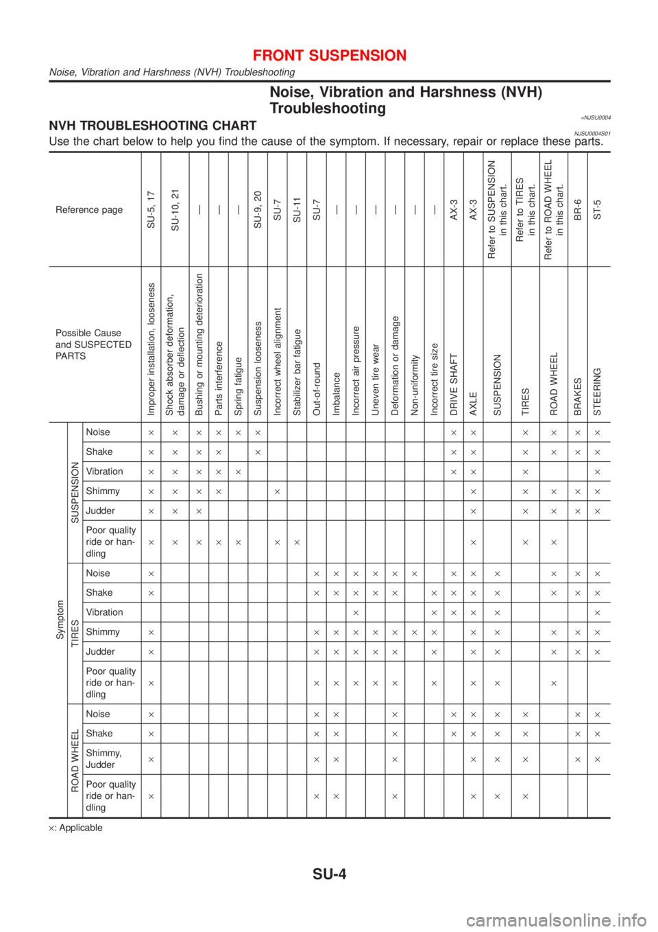
Noise, Vibration and Harshness (NVH)
Troubleshooting
=NJSU0004NVH TROUBLESHOOTING CHARTNJSU0004S01Use the chart below to help you find the cause of the symptom. If necessary, repair or replace these parts.
Reference page
SU-5, 17
SU-10, 21
Ð
Ð
Ð
SU-9, 20
SU-7
SU-11
SU-7
Ð
Ð
Ð
Ð
Ð
Ð
AX-3
AX-3
Refer to SUSPENSION
in this chart.
Refer to TIRES
in this chart.
Refer to ROAD WHEEL
in this chart.
BR-6
ST-5
Possible Cause
and SUSPECTED
PA R T S
Improper installation, looseness
Shock absorber deformation,
damage or deflection
Bushing or mounting deterioration
Parts interference
Spring fatigue
Suspension looseness
Incorrect wheel alignment
Stabilizer bar fatigue
Out-of-round
Imbalance
Incorrect air pressure
Uneven tire wear
Deformation or damage
Non-uniformity
Incorrect tire size
DRIVE SHAFT
AXLE
SUSPENSION
TIRES
ROAD WHEEL
BRAKES
STEERING Symptom
SUSPENSION
Noise´ ´ ´´´´ ´´ ´ ´ ´´
Shake´ ´ ´´ ´ ´´ ´ ´ ´´
Vibration´ ´ ´´´ ´´ ´ ´
Shimmy´´´´ ´ ´ ´ ´´´
Judder´´´ ´ ´ ´´´
Poor quality
ride or han-
dling´ ´ ´´´ ´´ ´ ´ ´
TIRES
Noise´ ´´´´´´ ´´ ´ ´ ´´
Shake´ ´´´´´ ´´´ ´ ´ ´´
Vibration´ ´´´ ´ ´
Shimmy´ ´´´´´´´ ´ ´ ´ ´´
Judder´ ´´´´´ ´ ´ ´ ´ ´´
Poor quality
ride or han-
dling´ ´´´´´ ´ ´ ´ ´
ROAD WHEEL
Noise´ ´´´´´´´´´
Shake´ ´´´´´´´´´
Shimmy,
Judder´´´´´´´´´
Poor quality
ride or han-
dling´´´´´´´
´: Applicable
FRONT SUSPENSION
Noise, Vibration and Harshness (NVH) Troubleshooting
SU-4