2001 NISSAN ALMERA N16 set clock
[x] Cancel search: set clockPage 105 of 2493

SEM886F
InstallationNJEM01071. Install crankshaft sprocket on crankshaft.
+Make sure mating marks on crankshaft sprocket face front
of engine.
SEM890F
2. Position crankshaft so that No. 1 piston is at TDC and key way
is at 12 o'clock.
SEM891F
3. Install slack side timing chain guide and timing chain tension
guide.
SEM892F
4. Install timing chain on crankshaft sprocket.
+Support chain with a suitable tool to keep the mating mark
aligned.
+Set timing chain by aligning its mating mark with that on
the crankshaft sprocket.
+Make sure sprocket's mating mark faces engine front.
SEM905F
5. Install camshaft sprocket.
+Set timing chain by aligning mating marks with those of
camshaft sprockets.
TIMING CHAINQG
Installation
EM-27
Page 172 of 2493

JEM121G
3. Remove front chain case.
+Move power steering fluid reservoir tank from the bracket.
+Loosen fixing bolts in the reverse order of that shown in the
figure and remove them.
+Remove No. 6, 10, and 11 bolts with the rubber washer as
space is limited for pulling them out.
SEM514G
CAUTION:
+While front chain case is removed, cover openings to pre-
vent entry of foreign material into engine.
+Do not remove two mass dampers on the back of cover.
SEM515G
4. Set the No. 1 piston to TDC on its compression stroke.
+Turn crankshaft pulley clockwise so that the alignment mark
(punched mark) on each camshaft sprocket is positioned as
shown in the figure.
+No position indicator is provided on the crankshaft pulley.
+When installing, color coded links on the secondary tim-
ing chain can be used as alignment marks. Marking may
not be necessary for removal; however, make alignment
marks as required because the alignment mark on fuel
injection pump sprocket may not be easy to see.
JEM124G
5. Remove chain tensioner.
a. Push the plunger of chain tensioner and keep it pressed with
a push pin.
JEM125G
b. Using a hexagon-head wrench (face to face: 5 mm, SST),
remove bolts to remove chain tensioner.
TIMING CHAINYD
Secondary Timing Chain (Cont'd)
EM-94
Page 210 of 2493

JEM175G
3. Install camshaft brackets.
+Install correctly, identifying brackets by the journal No. and
front mark on top surface.
JEM160G
4. Tighten bolts in the order shown in the figure according to the
following procedure:
a. Tighten to 2.0 N´m (0.2 kg-m, 17 in-lb).
+Make sure camshaft thrusting parts (on rear side) securely fit
in their mating parts on the cylinder head.
b. Tighten to 6 N´m (0.6 kg-m, 52 in-lb).
c. Tighten to 12 to 13 N´m (1.2 to 1.4 kg-m, 9 to 10 ft-lb).
5. Install camshaft sprockets.
+Camshaft sprockets are commonly used for RH and LH.
+Align camshaft sprocket and dowel pin on camshaft, and
install.
+Holding the hexagonal part of camshaft with a wrench, tighten
bolt securing camshaft sprocket.
6. Before installing spill tube after installing secondary timing
chain, check and adjust valve clearance. Refer to EM-132,
ªValve Clearanceº.
7. Hereafter, install in the reverse order of removal.
JEM176G
Valve ClearanceNJEM0068CHECKINGNJEM0068S01Check valve clearance while engine is cold and not running.
1. Set the No. 1 piston to TDC on its compression stroke.
+Turn crankshaft pulley clockwise so that the knock pin on cam-
shaft LH faces straight above. (No position indicator, etc. is
provided on the crankshaft pulley.)
JEM177G
2. Put an alignment mark with paint, etc. on the crankshaft pul-
ley and on the oil pump as an angle indicator.
CYLINDER HEADYD
Installation (Cont'd)
EM-132
Page 211 of 2493

JEM178G
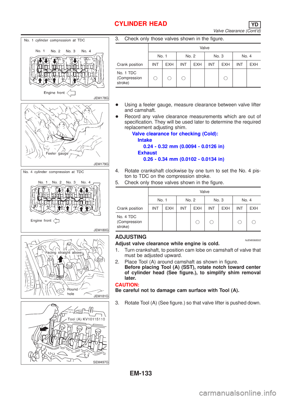
3. Check only those valves shown in the figure.
Crank positionValve
No. 1 No. 2 No. 3 No. 4
INT EXH INT EXH INT EXH INT EXH
No. 1 TDC
(Compression
stroke)jjj j
JEM179G
+Using a feeler gauge, measure clearance between valve lifter
and camshaft.
+Record any valve clearance measurements which are out of
specification. They will be used later to determine the required
replacement adjusting shim.
Valve clearance for checking (Cold):
Intake
0.24 - 0.32 mm (0.0094 - 0.0126 in)
Exhaust
0.26 - 0.34 mm (0.0102 - 0.0134 in)
JEM180G
4. Rotate crankshaft clockwise by one turn to set the No. 4 pis-
ton to TDC on the compression stroke.
5. Check only those valves shown in the figure.
Crank positionValve
No. 1 No. 2 No. 3 No. 4
INT EXH INT EXH INT EXH INT EXH
No. 4 TDC
(Compression
stroke)jj jj
JEM181G
ADJUSTINGNJEM0068S02Adjust valve clearance while engine is cold.
1. Turn crankshaft, to position cam lobe on camshaft of valve that
must be adjusted upward.
2. Place Tool (A) around camshaft as shown in figure.
Before placing Tool (A) (SST), rotate notch toward center
of cylinder head (See figure.), to simplify shim removal
later.
CAUTION:
Be careful not to damage cam surface with Tool (A).
SEM497G
3. Rotate Tool (A) (See figure.) so that valve lifter is pushed down.
CYLINDER HEADYD
Valve Clearance (Cont'd)
EM-133
Page 404 of 2493

17 ADJUSTMENT THROTTLE POSITION SWITCH CLOSED POSITION-II
Without CONSULT-II
1. Temporarily tighten sensor body fixing bolts as follows.
+Gradually move the sensor body clockwise and stop it when the continuity comes to exist, then temporarily
tighten sensor body fixing bolts.
SEF964W
2. Make sure two or three times that the continuity exists when the throttle valve is closed and continuity does not exist
when it is opened.
3. Remove 0.05 mm (0.0020 in) feeler gauge then insert 0.15 mm (0.0059 in) feeler gauge.
4. Make sure two or three times that the continuity does not exist when the throttle valve is closed.
5. Tighten throttle position sensor.
6. Check the continuity again.
Continuity does not exist while closing the throttle valve.
OK or NG
OK©GO TO 18.
NG©GO TO 16.
18 RESET THROTTLE POSITION SENSOR IDLE POSITION MEMORY
Without CONSULT-II
NOTE:
Always warm up engine to normal operating temperature. If engine is cool, the throttle position sensor idle posi-
tion memory will not be reset correctly.
1. Confirm that proper vacuum is applied. Refer to Test No. 10.
2. Attach blind cap to vacuum port from which vacuum hose to throttle opener was disconnected.
3. Start engine.
4. Warm up engine to normal operating temperature.
5. Stop engine. (Turn ignition switch ªOFFº.)
6. Turn ignition switch ªONº and wait at least 5 seconds.
SEF864V
7. Turn ignition switch ªOFFº and wait at least 9 seconds.
8. Repeat steps 6 and 7, 20 times.
©GO TO 19.
TROUBLE DIAGNOSIS Ð BASIC INSPECTIONQG
Basic Inspection (Cont'd)
EC-108
Page 411 of 2493

6 ADJUST THROTTLE POSITION SENSOR IDLE POSITION
With CONSULT-II
1. Loosen throttle position sensor fixing bolts.
2. Turn throttle position sensor body clockwise or counterclockwise until ªTHRTL POS SENº indication becomes 0.35 to
0.65V.
SEF964W
3. Tighten the throttle position sensor fixing bolts.
©GO TO 7.
7 RESET THROTTLE POSITION SENSOR IDLE POSITION MEMORY
With CONSULT-II
NOTE:
Always warm up engine to normal operating temperature. If engine is cool, the throttle position sensor idle posi-
tion memory will not be reset correctly.
1. Start engine and warm it up to normal operating temperature.
2. Select ªCLSD THL POSº in ªDATA MONITORº mode with CONSULT-II.
3. Stop engine. (Turn ignition switch ªOFFº.)
4. Turn ignition switch ªONº and wait at least 5 seconds.
SEF864V
5. Turn ignition switch ªOFFº and wait at least 9 seconds.
6. Repeat steps 4 and 6 until ªCLSD THL POSº indication changes to ªONº.
SEF061Y
©GO TO 11.
TROUBLE DIAGNOSIS Ð BASIC INSPECTIONQG
Basic Inspection (Cont'd)
EC-115
Page 1979 of 2493

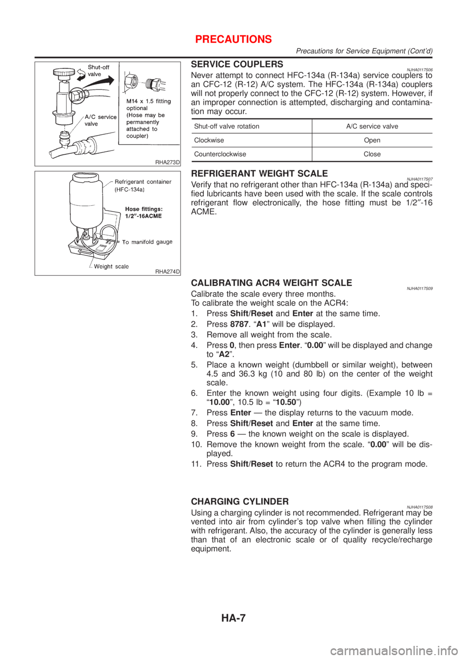
RHA273D
SERVICE COUPLERSNJHA0117S06Never attempt to connect HFC-134a (R-134a) service couplers to
an CFC-12 (R-12) A/C system. The HFC-134a (R-134a) couplers
will not properly connect to the CFC-12 (R-12) system. However, if
an improper connection is attempted, discharging and contamina-
tion may occur.
Shut-off valve rotation A/C service valve
Clockwise Open
Counterclockwise Close
RHA274D
REFRIGERANT WEIGHT SCALENJHA0117S07Verify that no refrigerant other than HFC-134a (R-134a) and speci-
fied lubricants have been used with the scale. If the scale controls
refrigerant flow electronically, the hose fitting must be 1/2²-16
ACME.
CALIBRATING ACR4 WEIGHT SCALENJHA0117S09Calibrate the scale every three months.
To calibrate the weight scale on the ACR4:
1. PressShift/ResetandEnterat the same time.
2. Press8787.ªA1º will be displayed.
3. Remove all weight from the scale.
4. Press0, then pressEnter.ª0.00º will be displayed and change
to ªA2º.
5. Place a known weight (dumbbell or similar weight), between
4.5 and 36.3 kg (10 and 80 lb) on the center of the weight
scale.
6. Enter the known weight using four digits. (Example 10 lb =
ª10.00º, 10.5 lb = ª10.50º)
7. PressEnterÐ the display returns to the vacuum mode.
8. PressShift/ResetandEnterat the same time.
9. Press6Ð the known weight on the scale is displayed.
10. Remove the known weight from the scale. ª0.00º will be dis-
played.
11. PressShift/Resetto return the ACR4 to the program mode.
CHARGING CYLINDERNJHA0117S08Using a charging cylinder is not recommended. Refrigerant may be
vented into air from cylinder's top valve when filling the cylinder
with refrigerant. Also, the accuracy of the cylinder is generally less
than that of an electronic scale or of quality recycle/recharge
equipment.
PRECAUTIONS
Precautions for Service Equipment (Cont'd)
HA-7
Page 2114 of 2493

WARNING CHIME....................................................... 113
Component Parts and Harness Connector
Location ................................................................... 113
System Description .................................................. 113
Wiring Diagram - CHIME - ...................................... 115
Trouble Diagnoses................................................... 117
FRONT WIPER AND WASHER..................................123
System Description ..................................................123
Wiring Diagram - WIPER - ......................................125
Removal and Installation .........................................127
Washer Nozzle Adjustment .....................................128
Washer Tube Layout ...............................................128
REAR WIPER AND WASHER....................................129
Wiring Diagram - WIP/R -........................................129
Removal and Installation .........................................131
Washer Nozzle Adjustment .....................................131
Washer Tube Layout ...............................................132
HEADLAMP WASHER................................................133
Wiring Diagram - HLC - ...........................................133
Washer Tube Layout ...............................................134
HORN...........................................................................135
Wiring Diagram - HORN - .......................................135
CIGARETTE LIGHTER................................................136
Wiring Diagram - CIGAR -.......................................136
CLOCK.........................................................................137
Wiring Diagram - CLOCK -......................................137
REAR WINDOW DEFOGGER.....................................138
System Description ..................................................138
Schematic ................................................................139
Wiring Diagram - DEF - ...........................................140
Trouble Diagnoses...................................................143
Electrical Components Inspection ...........................146
Filament Check ........................................................147
Filament Repair .......................................................148
AUDIO..........................................................................149
System Description ..................................................149
Schematic ................................................................151
Wiring Diagram - AUDIO - .......................................152
Trouble Diagnoses...................................................160
Inspection.................................................................161
AUDIO ANTENNA.......................................................162
Location of Antenna .................................................162
Antenna Rod Replacement .....................................162
HEATED SEAT............................................................163
Wiring Diagram - H/SEAT - .....................................163
POWER SUNROOF.....................................................165
Wiring Diagram - SROOF - .....................................165
Trouble Diagnoses...................................................166
DOOR MIRROR...........................................................167
Wiring Diagram - MIRROR - ...................................167
POWER WINDOW.......................................................169
System Description ..................................................169Schematic ................................................................171
Wiring Diagram - WINDOW - ..................................172
Trouble Diagnoses...................................................176
POWER DOOR LOCK.................................................177
System Description ..................................................177
Schematic ................................................................178
Wiring Diagram - D/LOCK -.....................................180
Trouble Diagnoses...................................................187
POWER DOOR LOCK - SUPER LOCK -...................196
System Description ..................................................196
Schematic ................................................................198
Wiring Diagram - S/LOCK - .....................................200
Trouble Diagnoses...................................................207
MULTI-REMOTE CONTROL SYSTEM.......................220
System Description ..................................................220
Wiring Diagram - MULTI - .......................................221
Trouble Diagnoses...................................................223
ID Code Entry Procedure ........................................227
Remote Controller Battery Replacement.................228
TIME CONTROL UNIT................................................229
Description ...............................................................229
Trouble Diagnoses...................................................230
Schematic ................................................................232
NATS (NISSAN ANTI-THEFT SYSTEM).....................234
Component Parts and Harness Connetor
Location ...................................................................234
System Description ..................................................234
System Composition ................................................236
Wiring Diagram - NATS -.........................................237
CONSULT-II .............................................................238
Trouble Diagnoses...................................................241
How to Replace NATS IMMU ..................................258
NAVIGATION SYSTEM...............................................259
Precautions ..............................................................259
Component Parts Location ......................................260
System Description ..................................................261
Schematic ................................................................269
Wiring Diagram - NAVI - ..........................................270
Self-diagnosis Mode ................................................278
Confirmation/Adjustment Mode ...............................281
Control Panel Mode .................................................293
Guide Volume Setting ..............................................300
Anti-theft System .....................................................301
CONSULT-II .............................................................302
Trouble Diagnoses...................................................303
This Condition Is Not Abnormal...............................309
Program Loading .....................................................318
ELECTRICAL UNITS LOCATION...............................319
Engine Compartment ...............................................319
Passenger Compartment/LHD Models ....................320
Passenger Compartment/RHD Models ...................322
CONTENTS(Cont'd)
EL-2