2001 NISSAN ALMERA N16 turn signal
[x] Cancel search: turn signalPage 59 of 2493

NJMA0004
General maintenance includes those items which should be checked during the normal day-to-day operation
of the vehicle. They are essential if the vehicle is to continue operating properly. The owners can perform the
checks and inspections themselves or they can have their NISSAN dealers do them for a nominal charge.
OUTSIDE THE VEHICLE
The maintenance items listed here should be performed from time to time, unless otherwise specified.
Item Reference page
TiresCheck the pressure with a gauge periodically when at a service station,
including the spare, and adjust to the specified pressure if necessary. Check
carefully for damage, cuts or excessive wear.Ð
Windshield wiper
bladesCheck for cracks or wear if not functioning correctly. Ð
Doors and engine
hoodCheck that all doors, the engine hood, the trunk lid and back door operate
properly. Also ensure that all latches lock securely. Lubricate if necessary.
Make sure that the secondary latch keeps the hood from opening when the
primary latch is released.
When driving in areas using road salt or other corrosive materials, check for
lubrication frequently.BT-7
BT-16
Tire rotationTires should be rotated every 10,000 km (6,000 miles). SU-7
INSIDE THE VEHICLE
The maintenance items listed here should be checked on a regular basis, such as when performing periodic maintenance, cleaning the
vehicle, etc.
Item Reference page
LampsMake sure that the headlamps, stop lamps, tail lamps, turn signal lamps,
and other lamps are all operating properly and installed securely. Also check
headlamp aim.Ð
Warning lamps and
chimesMake sure that all warning lamps and buzzers/chimes are operating prop-
erly.Ð
Steering wheelCheck that it has the specified play.
Check for changes in the steering conditions, such as excessive free play,
hard steering or strange noises.
Free play: Less than 35 mm (1.38 in)Ð
Seat beltsCheck that all parts of the seat belt system (e.g. buckles, anchors, adjusters
and retractors) operate properly and smoothly, and are installed securely.
Check the belt webbing for cuts, fraying, wear or damage.RS-4
UNDER THE HOOD AND VEHICLE
The maintenance items listed here should be checked periodically e.g. each time you check the engine oil or refuel.
Item Reference page
Windshield washer
fluidCheck that there is adequate fluid in the tank. Ð
Engine coolant levelCheck the coolant level when the engine is cold. LC-18, LC-43
Engine oil levelCheck the level after parking the vehicle (on level ground) and turning off
the engine.LC-8, LC-30
Brake and clutch
fluid levelsMake sure that the brake and clutch fluid levels are between the ªMAXº and
ªMINº lines on the reservoir.BR-7
BatteryCheck the fluid level in each cell. It should be between the ªMAXº and ªMINº
lines.Ð
GENERAL MAINTENANCE
MA-3
Page 328 of 2493

System DescriptionNJEC0015S02
SEF742M
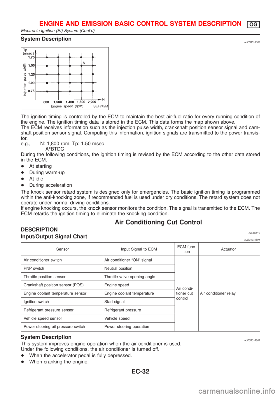
The ignition timing is controlled by the ECM to maintain the best air-fuel ratio for every running condition of
the engine. The ignition timing data is stored in the ECM. This data forms the map shown above.
The ECM receives information such as the injection pulse width, crankshaft position sensor signal and cam-
shaft position sensor signal. Computing this information, ignition signals are transmitted to the power transis-
tor.
e.g., N: 1,800 rpm, Tp: 1.50 msec
AÉBTDC
During the following conditions, the ignition timing is revised by the ECM according to the other data stored
in the ECM.
+At starting
+During warm-up
+At idle
+During acceleration
The knock sensor retard system is designed only for emergencies. The basic ignition timing is programmed
within the anti-knocking zone, if recommended fuel is used under dry conditions. The retard system does not
operate under normal driving conditions.
If engine knocking occurs, the knock sensor monitors the condition. The signal is transmitted to the ECM. The
ECM retards the ignition timing to eliminate the knocking condition.
Air Conditioning Cut Control
DESCRIPTIONNJEC0016Input/Output Signal ChartNJEC0016S01
Sensor Input Signal to ECMECM func-
tionActuator
Air conditioner switch Air conditioner ªONº signal
Air condi-
tioner cut
controlAir conditioner relay PNP switch Neutral position
Throttle position sensor Throttle valve opening angle
Crankshaft position sensor (POS) Engine speed
Engine coolant temperature sensor Engine coolant temperature
Ignition switch Start signal
Refrigerant pressure sensor Refrigerant pressure
Vehicle speed sensor Vehicle speed
Power steering oil pressure switch Power steering operation
System DescriptionNJEC0016S02This system improves engine operation when the air conditioner is used.
Under the following conditions, the air conditioner is turned off.
+When the accelerator pedal is fully depressed.
+When cranking the engine.
ENGINE AND EMISSION BASIC CONTROL SYSTEM DESCRIPTIONQG
Electronic Ignition (EI) System (Cont'd)
EC-32
Page 347 of 2493

21 CHECK HEATED OXYGEN SENSOR 1 (FRONT) SIGNAL
With CONSULT-II
1. Stop engine.
2. Replace heated oxygen sensor 1 (front).
3. Start engine and warm it up to normal operating temperature.
4. Run engine at approx. 2,000 rpm for approx. 2 minutes under no-load.
5. See ªHO2S1 MNTR (B1)º in ªDATA MONITORº mode.
6. Running engine at 2,000 rpm under no-load (engine is warmed up to normal operating temperature.), check that the
monitor fluctuates between ªLEANº and ªRICHº more than 5 times during 10 seconds.
1 time: RICH®LEAN®RICH
2 times: RICH®LEAN®RICH®LEAN®RICH
Without CONSULT-II
1. Stop engine.
2. Replace heated oxygen sensor 1 (front).
3. Start engine and warm it up to normal operating temperature.
4. Run engine at approx. 2,000 rpm for approx. 2 minutes under no-load.
5. Set voltmeter probe between ECM terminal 62 and ground.
6. Make sure that the voltage fluctuates between 0 to 0.3V and 0.6 to 1.0V more than 5 times during 10 seconds at 2,000
rpm.
1 time: 0 - 0.3V®0.6 - 1.0V®0 - 0.3V
2 times: 0 - 0.3V®0.6 - 1.0V®0 - 0.3V®0.6 - 1.0V®0 - 0.3V
OK or NG
OK©INSPECTION END
NG©GO TO 22.
22 DETECT MALFUNCTIONING PART
Check the following.
1. Check fuel pressure regulator. Refer to EC-39.
2. Check mass air flow sensor and its circuit. Refer to EC-152.
3. Check injector and its circuit. Refer to EC-446.
Clean or replace if necessary.
4. Check engine coolant temperature sensor and its circuit. Refer to EC-163.
5. Check ECM function by substituting another known-good ECM.
(ECM may be the cause of a problem, but this is rarely the case.)
©GO TO 3.
23 CHECK HEATED OXYGEN SENSOR 1 (FRONT) HARNESS
1. Turn off engine and disconnect battery ground cable.
2. Disconnect ECM harness connector.
3. Disconnect heated oxygen sensor 1 (front) harness connector.
4. Check harness continuity between ECM terminal 62 and heated oxygen sensor 1 (front) harness connector terminal 1.
Refer to Wiring Diagram, EC-176.
Continuity should exist.
OK or NG
OK©GO TO 25.
NG©GO TO 24.
24 REPAIR OR REPLACE
Repair or replace harness between ECM and heated oxygen sensor 1 (front).
©GO TO 3.
BASIC SERVICE PROCEDUREQG
Inspection Procedure (Cont'd)
EC-51
Page 381 of 2493
![NISSAN ALMERA N16 2001 Electronic Repair Manual Freeze frame data
item*Description
ENGINE SPEED
[rpm]+The engine speed at the moment a malfunction is detected is displayed.
VEHICL SPEED
[km/h] or [mph]+The vehicle speed at the moment a malfunction NISSAN ALMERA N16 2001 Electronic Repair Manual Freeze frame data
item*Description
ENGINE SPEED
[rpm]+The engine speed at the moment a malfunction is detected is displayed.
VEHICL SPEED
[km/h] or [mph]+The vehicle speed at the moment a malfunction](/manual-img/5/57351/w960_57351-380.png)
Freeze frame data
item*Description
ENGINE SPEED
[rpm]+The engine speed at the moment a malfunction is detected is displayed.
VEHICL SPEED
[km/h] or [mph]+The vehicle speed at the moment a malfunction is detected is displayed.
ABSOL TH´P/S [%]+The throttle valve opening angle at the moment a malfunction is detected is displayed.
B/FUEL SCHDL
[msec]+The base fuel schedule at the moment a malfunction is detected is displayed.
INT/A TEMP SE [ÉC]
or [ÉF]+The intake air temperature at the moment a malfunction is detected is displayed.
*: The items are the same as those of 1st trip freeze frame data.
DATA MONITOR MODENJEC0034S06
Monitored item [Unit]ECM
input
signalsMain
signalsDescription Remarks
ENG SPEED [rpm]jj+Indicates the engine speed computed from
the POS signal of the crankshaft position
sensor.+Accuracy becomes poor if engine
speed drops below the idle rpm.
+If the signal is interrupted while the
engine is running, an abnormal
value may be indicated.
MAS A/F SE-B1 [V]jj+The signal voltage of the mass air flow sen-
sor is displayed.+When the engine is stopped, a cer-
tain value is indicated.
B/FUEL SCHDL
[msec]+ªBase fuel scheduleº indicates the fuel
injection pulse width programmed into
ECM, prior to any learned on board correc-
tion.
A/F ALPHA-B1 [%]j+Indicates the mean value of the air-fuel
ratio feedback correction factor per cycle.+When the engine is stopped, a cer-
tain value is indicated.
+This data also includes the data for
the air-fuel ratio learning control.
COOLAN TEMP/S
[ÉC] or [ÉF]jj+The engine coolant temperature (deter-
mined by the signal voltage of the engine
coolant temperature sensor) is displayed.+When the engine coolant tempera-
ture sensor is open or short-
circuited, ECM enters fail-safe
mode. The engine coolant tempera-
ture determined by the ECM is dis-
played.
HO2S1 (B1) [V]jj+The signal voltage of the heated oxygen
sensor 1 (front) is displayed.
HO2S2 (B1) [V]j+The signal voltage of the heated oxygen
sensor 2 (rear) is displayed.
HO2S1 MNTR (B1)
[RICH/LEAN]j+Display of heated oxygen sensor 1 (front)
signal during air-fuel ratio feedback control:
RICH ... means the mixture became ªrichº,
and control is being affected toward a
leaner mixture.
LEAN ... means the mixture became ªleanº,
and control is being affected toward a rich
mixture.+After turning ON the ignition switch,
ªRICHº is displayed until air-fuel
mixture ratio feedback control
begins.
+When the air-fuel ratio feedback is
clamped, the value just before the
clamping is displayed continuously.
ON BOARD DIAGNOSTIC SYSTEM DESCRIPTIONQG
CONSULT-II (Cont'd)
EC-85
Page 384 of 2493
![NISSAN ALMERA N16 2001 Electronic Repair Manual Monitored item [Unit]ECM
input
signalsMain
signalsDescription Remarks
IDL A/V LEARN+Display the condition of idle air volume
learning
YET ... Idle air volume learning has not
been performed yet.
CMPLT NISSAN ALMERA N16 2001 Electronic Repair Manual Monitored item [Unit]ECM
input
signalsMain
signalsDescription Remarks
IDL A/V LEARN+Display the condition of idle air volume
learning
YET ... Idle air volume learning has not
been performed yet.
CMPLT](/manual-img/5/57351/w960_57351-383.png)
Monitored item [Unit]ECM
input
signalsMain
signalsDescription Remarks
IDL A/V LEARN+Display the condition of idle air volume
learning
YET ... Idle air volume learning has not
been performed yet.
CMPLT ... Idle air volume learning has
already been performed successfully.
INCMP ... Idle air volume learning has not
been performed successfully.
TRVL AFTER MIL
[km] or [Mile]+Distance traveled while MI is activated
VOLTAGE [V]+Voltage measured by the voltage probe.
PULSE
[msec] or [Hz] or [%]+Pulse width, frequency or duty cycle mea-
sured by the pulse probe.+Only ª#º is displayed if item is
unable to be measured.
+Figures with ª#ºs are temporary
ones. They are the same figures as
an actual piece of data which was
just previously measured.
*: If so equipped
NOTE:
Any monitored item that does not match the vehicle being diagnosed is deleted from the display automatically.
DATA MONITOR (SPEC) MODENJEC0034S11
Monitored item [Unit]ECM
input
signalsMain
signalsDescription Remarks
MAS A/F SE-B1 [V]jj+The signal voltage of the mass air flow sen-
sor specification is displayed.+When the engine is running, speci-
fication range is indicated.
B/FUEL SCHDL
[msec]+ªBase fuel scheduleº indicates the fuel
injection pulse width programmed into
ECM, prior to any learned on board correc-
tion.+When the engine is running, speci-
fication range is indicated.
A/F ALPHA-B1 [%]j+Indicates the mean value of the air-fuel
ratio feedback correction factor per cycle.+When the engine is running, speci-
fication range is indicated.
+This data also includes the data for
the air-fuel ratio learning control.
NOTE:
Any monitored item that does not match the vehicle being diagnosed is deleted from the display automatically.
ACTIVE TEST MODENJEC0034S07
TEST ITEM CONDITION JUDGEMENT CHECK ITEM (REMEDY)
FUEL INJECTION+Engine: Return to the original
trouble condition
+Change the amount of fuel injec-
tion using CONSULT-II.If trouble symptom disappears, see
CHECK ITEM.+Harness and connector
+Fuel injectors
+Heated oxygen sensor 1 (front)
IGNITION TIMING+Engine: Return to the original
trouble condition
+Timing light: Set
+Retard the ignition timing using
CONSULT-II.If trouble symptom disappears, see
CHECK ITEM.+ªIdle Air Volume Leaningº (Refer
to EC-55.)
+Camshaft position sensor
(PHASE)
+Crankshaft position sensor
(POS)
+Engine component parts and
installing conditions
ON BOARD DIAGNOSTIC SYSTEM DESCRIPTIONQG
CONSULT-II (Cont'd)
EC-88
Page 385 of 2493

TEST ITEM CONDITION JUDGEMENT CHECK ITEM (REMEDY)
IACV-AAC/V
OPENING+Engine: After warming up, idle
the engine.
+Change the IACV-AAC valve
opening steps using CONSULT-
II.Engine speed changes according
to the opening steps.+Harness and connector
+IACV-AAC valve
POWER BAL-
ANCE+Engine: After warming up, idle
the engine.
+Air conditioner switch ªOFFº
+Shift lever ªNº
+Cut off each injector signal one
at a time using CONSULT-II.Engine runs rough or dies.+Harness and connector
+Compression
+Injectors
+Power transistor
+Spark plugs
+Ignition coils
COOLING FAN+Ignition switch: ON
+Turn the cooling fan ªONº and
ªOFFº using CONSULT-II.Cooling fan moves and stops.+Harness and connector
+Cooling fan motor
ENG COOLANT
TEMP+Engine: Return to the original
trouble condition
+Change the engine coolant tem-
perature indication using CON-
SULT-II.If trouble symptom disappears, see
CHECK ITEM.+Harness and connector
+Engine coolant temperature sen-
sor
+Fuel injectors
FUEL PUMP
RELAY+Ignition switch: ON
(Engine stopped)
+Turn the fuel pump relay ªONº
and ªOFFº using CONSULT-II
and listen to operating sound.Fuel pump relay makes the operat-
ing sound.+Harness and connector
+Fuel pump relay
EGR VOL
CONT/V
(If so equipped)+Engine: After warming up, idle
the engine.
+Change the EGR volume control
valve opening step using CON-
SULT-II.Engine speed changes according
to the opening step.+Harness and connector
+EGR volume control valve
VALVE TIMING
SOL+Ignition switch: ON
+Turn intake valve timing control
solenoid valve ªONº and ªOFFº
using CONSULT-II and listen for
operating sound.Intake valve timing control solenoid
valve makes an operating sound.+Harness and connector
+Intake valve timing control sole-
noid valve
PURG VOL
CONT/V+Engine: After warming up, idle
the engine.
+Change the EVAP canister
purge volume control solenoid
valve opening percent using
CONSULT-II.Engine speed changes according
to the opening percent.+Harness and connector
+EVAP canister purge volume
control solenoid valve
DTC AND SRT CONFIRMATION MODENJEC0034S08This mode is not available for models without Euro-OBD system.
SRT STATUS ModeNJEC0034S0801For details, refer to ªSYSTEM READINESS TEST (SRT) CODEº,
EC-60.
SRT Work Support ModeNJEC0034S0803This mode enables a technician to drive a vehicle to set the SRT
while monitoring the SRT status.
ON BOARD DIAGNOSTIC SYSTEM DESCRIPTIONQG
CONSULT-II (Cont'd)
EC-89
Page 398 of 2493

11 CHECK THROTTLE POSITION SWITCH CLOSED POSITION-II
With CONSULT-II
1. Connect ªCONSULT-IIº to the data link connector and select ªENGINEº from the menu. Refer to EC-81.
2. Turn ignition switch ªONº.
3. Select ªTP SW/TP SEN IDLE POSI ADJº in ªWORK SUPPORTº mode with CONSULT-II.
4. Read ªCLSD THL/P SWº signal under the following conditions.
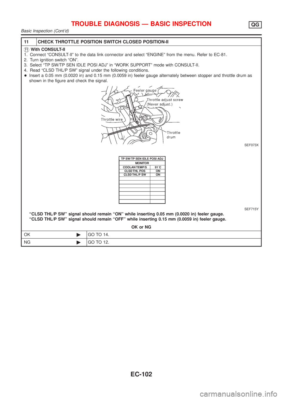
+Insert a 0.05 mm (0.0020 in) and 0.15 mm (0.0059 in) feeler gauge alternately between stopper and throttle drum as
shown in the figure and check the signal.
SEF073X
SEF715Y
ªCLSD THL/P SWº signal should remain ªONº while inserting 0.05 mm (0.0020 in) feeler gauge.
ªCLSD THL/P SWº signal should remain ªOFFº while inserting 0.15 mm (0.0059 in) feeler gauge.
OK or NG
OK©GO TO 14.
NG©GO TO 12.
TROUBLE DIAGNOSIS Ð BASIC INSPECTIONQG
Basic Inspection (Cont'd)
EC-102
Page 399 of 2493

12 ADJUSTMENT THROTTLE POSITION SWITCH CLOSED POSITION-I
With CONSULT-II
1. Loosen throttle position sensor fixing bolts.
2. Confirm that proper vacuum is applied. Refer to test No. 10. During adjustment, vacuum should be applied.
3. Insert 0.05 mm (0.0020 in) feeler gauge between stopper and throttle drum as shown in the figure.
SEF073X
4. Turn throttle position sensor body counterclockwise until ªCLSD THL/P SWº signal switches to ªOFFº.
SEF863Y
©GO TO 13.
TROUBLE DIAGNOSIS Ð BASIC INSPECTIONQG
Basic Inspection (Cont'd)
EC-103