2001 NISSAN ALMERA N16 turn signal
[x] Cancel search: turn signalPage 434 of 2493
![NISSAN ALMERA N16 2001 Electronic Repair Manual TERMI-
NAL
NO.WIRE
COLORITEM CONDITION DATA (DC Voltage)
72* P/B EGR temperature sensor[Engine is running]
+Warm-up condition
+Idle speedLess than 4.5V
[Engine is running]
+Warm-up condition
+EGR syst](/manual-img/5/57351/w960_57351-433.png "NISSAN ALMERA N16 2001 Electronic Repair Manual TERMI-
NAL
NO.WIRE
COLORITEM CONDITION DATA (DC Voltage)
72* P/B EGR temperature sensor[Engine is running]
+Warm-up condition
+Idle speedLess than 4.5V
[Engine is running]
+Warm-up condition
+EGR syst")
TERMI-
NAL
NO.WIRE
COLORITEM CONDITION DATA (DC Voltage)
72* P/B EGR temperature sensor[Engine is running]
+Warm-up condition
+Idle speedLess than 4.5V
[Engine is running]
+Warm-up condition
+EGR system is operating0 - 1.0V
73 BMass air flow sensor
ground[Engine is running]
+Warm-up condition
+Idle speedApproximately 0V
74 R/LRefrigerant pressure
sensor[Engine is running]
+Air conditioner switch is ªONº
(Compressor operates)1.0 - 4.0V
[Engine is running]
+Warm-up condition
+Idle speed
+Air conditioner switch is turned from ªONº to
ªOFFºVoltage is gradually decreasing.
81 W Knock sensor[Engine is running]
+Idle speed1.0 - 4.0V
85 RCrankshaft position sen-
sor (POS)[Engine is running]
+Warm-up condition
+Idle speed3.0 - 4.0V
SEF979W
[Engine is running]
+Engine speed is 2,000 rpm3.0 - 4.0V
SEF980W
86 PU/R Vehicle speed sensor[Engine is running]
+Lift up the vehicle
+Vehicle speed is 40 km/h (25 MPH)2.5-3V
SEF976W
91 PU A/T check signal[Engine is running]
+Idle speed0 - Approximately 5V
92 Y Throttle position sensor[Engine is running]
+Accelerator pedal released0.15 - 0.85V
[Ignition switch ªONº]
+Accelerator pedal fully depressed3.5 - 4.7V
TROUBLE DIAGNOSIS Ð GENERAL DESCRIPTIONQG
ECM Terminals and Reference Value (Cont'd)
EC-138
Page 453 of 2493

7 CHECK INPUT SIGNAL CIRCUIT
1. Check harness continuity between mass air flow sensor harness connector terminal 1 and ECM terminal 61.
Refer to wiring diagram.
Continuity should exist.
2. Also check harness for short to ground and short to power.
OK or NG
OK©GO TO 8.
NG©Repair open circuit or short to ground or short to power in harness or connectors.
8 CHECK MASS AIR FLOW SENSOR
Refer to ªComponent Inspectionº, EC-157.
OK or NG
OK©GO TO 9.
NG©Replace mass air flow sensor.
9 CHECK INTERMITTENT INCIDENT
Perform ªTROUBLE DIAGNOSIS FOR INTERMITTENT INCIDENTº, EC-144.
©INSPECTION END
SEF993W
SEF987W
Component InspectionNJEC0058MASS AIR FLOW SENSORNJEC0058S011. Turn ignition switch ªONº.
2. Start engine and warm it up to normal operating temperature.
3. Check voltage between ECM terminal 61 (Mass air flow sen-
sor signal) and ground.
Conditions Voltage V
Ignition switch ªONº (Engine stopped.) Less than 1.2
Idle (Engine is warmed-up to normal operating
temperature.)1.0 - 1.7
2,500 rpm (Engine is warmed-up to normal oper-
ating temperature.)1.7 - 2.1
Idle to about 4,000 rpm* 1.0 - 1.7 to Approx. 4.0
*: Check for linear voltage rise in response to increases to about 4,000 rpm in
engine speed.
4. If the voltage is out of specification, disconnect mass air flow
sensor harness connector and connect it again. Repeat above
check.
5. If NG, remove mass air flow sensor from air duct. Check hot
film for damage or dust.
DTC P0100 MASS AIR FLOW SENSOR (MAFS)QG
Diagnostic Procedure (Cont'd)
EC-157
Page 454 of 2493

SEC500C
Component DescriptionNJEC0066The intake air temperature sensor is built into the mass air flow
sensor. The sensor detects intake air temperature and transmits a
signal to the ECM.
The temperature sensing unit uses a thermistor which is sensitive
to the change in temperature. Electrical resistance of the thermistor
decreases in response to the temperature rise.
Intake air temperature
ÉC (ÉF)Voltage*
VResistance
kW
25 (77) 3.3 1.9 - 2.1
80 (176) 1.28 0.31 - 0.37
*: These data are reference values and are measured between ECM terminal 64
(Intake air temperature sensor) and ground.
CAUTION:
Do not use ECM ground terminals when measuring input/
output voltage. Doing so may result in damage to the ECM's
transistor. Use a ground other than ECM terminals, such as
the ground.
On Board Diagnosis LogicNJEC0067
DTC No. Malfunction is detected when ... Check Items (Possible Cause)
P0110
0110An excessively low or high voltage from the sensor is sent
to ECM.+Harness or connectors
(The sensor circuit is open or shorted.)
+Intake air temperature sensor
DTC Confirmation ProcedureNJEC0068NOTE:
If ªDTC Confirmation Procedureº has been previously conducted,
always turn ignition switch ªOFFº and wait at least 9 seconds
before conducting the next test.
DTC P0110 INTAKE AIR TEMPERATURE SENSORQG
Component Description
EC-158
Page 459 of 2493
SEF594K
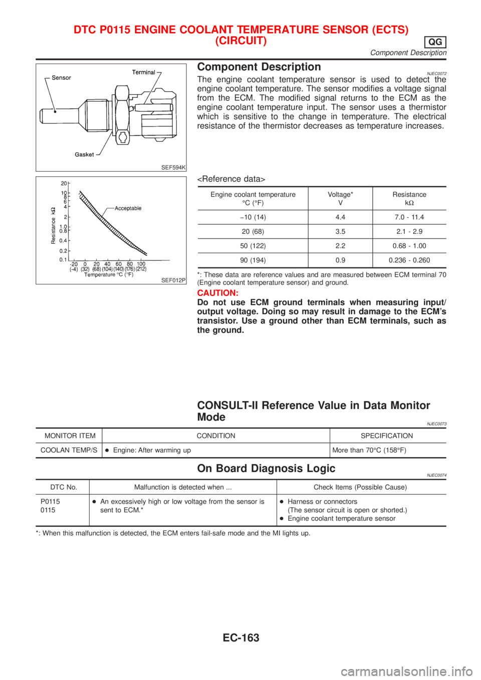
Component DescriptionNJEC0072The engine coolant temperature sensor is used to detect the
engine coolant temperature. The sensor modifies a voltage signal
from the ECM. The modified signal returns to the ECM as the
engine coolant temperature input. The sensor uses a thermistor
which is sensitive to the change in temperature. The electrical
resistance of the thermistor decreases as temperature increases.
SEF012P
Engine coolant temperature
ÉC (ÉF)Voltage*
VResistance
kW
þ10 (14) 4.4 7.0 - 11.4
20 (68) 3.5 2.1 - 2.9
50 (122) 2.2 0.68 - 1.00
90 (194) 0.9 0.236 - 0.260
*: These data are reference values and are measured between ECM terminal 70
(Engine coolant temperature sensor) and ground.
CAUTION:
Do not use ECM ground terminals when measuring input/
output voltage. Doing so may result in damage to the ECM's
transistor. Use a ground other than ECM terminals, such as
the ground.
CONSULT-II Reference Value in Data Monitor
Mode
NJEC0073
MONITOR ITEM CONDITION SPECIFICATION
COOLAN TEMP/S+Engine: After warming up More than 70ÉC (158ÉF)
On Board Diagnosis LogicNJEC0074
DTC No. Malfunction is detected when ... Check Items (Possible Cause)
P0115
0115+An excessively high or low voltage from the sensor is
sent to ECM.*+Harness or connectors
(The sensor circuit is open or shorted.)
+Engine coolant temperature sensor
*: When this malfunction is detected, the ECM enters fail-safe mode and the MI lights up.
DTC P0115 ENGINE COOLANT TEMPERATURE SENSOR (ECTS)
(CIRCUIT)
QG
Component Description
EC-163
Page 469 of 2493
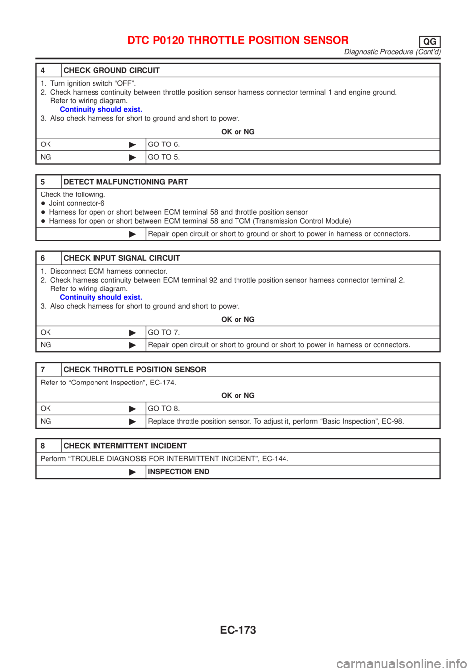
4 CHECK GROUND CIRCUIT
1. Turn ignition switch ªOFFº.
2. Check harness continuity between throttle position sensor harness connector terminal 1 and engine ground.
Refer to wiring diagram.
Continuity should exist.
3. Also check harness for short to ground and short to power.
OK or NG
OK©GO TO 6.
NG©GO TO 5.
5 DETECT MALFUNCTIONING PART
Check the following.
+Joint connector-6
+Harness for open or short between ECM terminal 58 and throttle position sensor
+Harness for open or short between ECM terminal 58 and TCM (Transmission Control Module)
©Repair open circuit or short to ground or short to power in harness or connectors.
6 CHECK INPUT SIGNAL CIRCUIT
1. Disconnect ECM harness connector.
2. Check harness continuity between ECM terminal 92 and throttle position sensor harness connector terminal 2.
Refer to wiring diagram.
Continuity should exist.
3. Also check harness for short to ground and short to power.
OK or NG
OK©GO TO 7.
NG©Repair open circuit or short to ground or short to power in harness or connectors.
7 CHECK THROTTLE POSITION SENSOR
Refer to ªComponent Inspectionº, EC-174.
OK or NG
OK©GO TO 8.
NG©Replace throttle position sensor. To adjust it, perform ªBasic Inspectionº, EC-98.
8 CHECK INTERMITTENT INCIDENT
Perform ªTROUBLE DIAGNOSIS FOR INTERMITTENT INCIDENTº, EC-144.
©INSPECTION END
DTC P0120 THROTTLE POSITION SENSORQG
Diagnostic Procedure (Cont'd)
EC-173
Page 470 of 2493
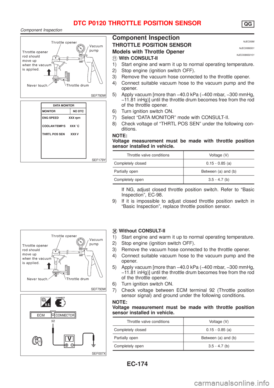
SEF793W
SEF179Y
Component InspectionNJEC0086THROTTLE POSITION SENSORNJEC0086S01Models with Throttle OpenerNJEC0086S0101With CONSULT-II
1) Start engine and warm it up to normal operating temperature.
2) Stop engine (ignition switch OFF).
3) Remove the vacuum hose connected to the throttle opener.
4) Connect suitable vacuum hose to the vacuum pump and the
opener.
5) Apply vacuum [more than þ40.0 kPa (þ400 mbar, þ300 mmHg,
þ11.81 inHg)] until the throttle drum becomes free from the rod
of the throttle opener.
6) Turn ignition switch ON.
7) Select ªDATA MONITORº mode with CONSULT-II.
8) Check voltage of ªTHRTL POS SENº under the following con-
ditions.
NOTE:
Voltage measurement must be made with throttle position
sensor installed in vehicle.
Throttle valve conditions Voltage (V)
Completely closed 0.15 - 0.85 (a)
Partially open Between (a) and (b)
Completely open 3.5 - 4.7 (b)
If NG, adjust closed throttle position switch. Refer to ªBasic
Inspectionº, EC-98.
9) If it is impossible to adjust closed throttle position switch in
ªBasic Inspectionº, replace throttle position sensor.
SEF793W
SEF007X
Without CONSULT-II
1) Start engine and warm it up to normal operating temperature.
2) Stop engine (ignition switch OFF).
3) Remove the vacuum hose connected to the throttle opener.
4) Connect suitable vacuum hose to the vacuum pump and the
opener.
5) Apply vacuum [more than þ40.0 kPa (þ400 mbar, þ300 mmHg,
þ11.81 inHg)] until the throttle drum becomes free from the rod
of the throttle opener.
6) Turn ignition switch ON.
7) Check voltage between ECM terminal 92 (Throttle position
sensor signal) and ground under the following conditions.
NOTE:
Voltage measurement must be made with throttle position
sensor installed in vehicle.
Throttle valve conditions Voltage (V)
Completely closed 0.15 - 0.85 (a)
Partially open Between (a) and (b)
Completely open 3.5 - 4.7 (b)
DTC P0120 THROTTLE POSITION SENSORQG
Component Inspection
EC-174
Page 471 of 2493
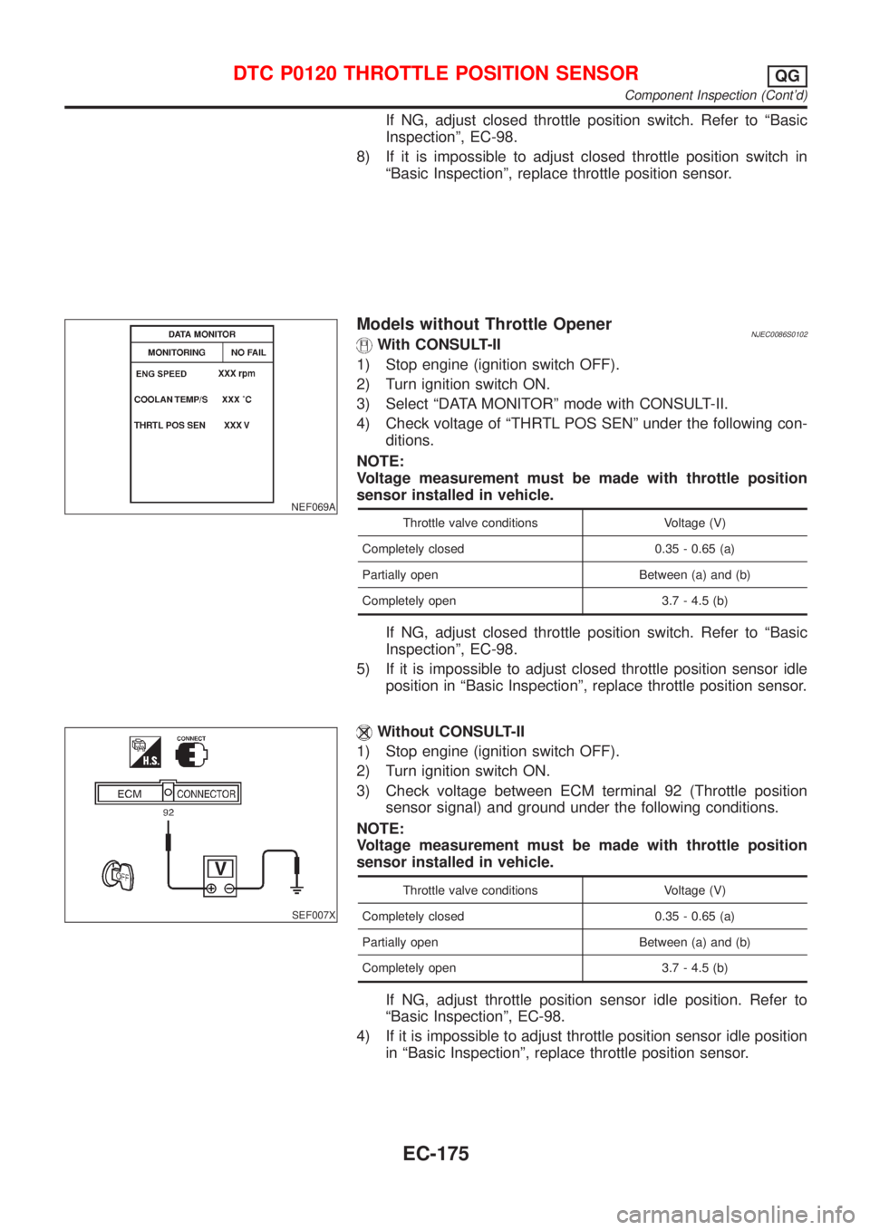
If NG, adjust closed throttle position switch. Refer to ªBasic
Inspectionº, EC-98.
8) If it is impossible to adjust closed throttle position switch in
ªBasic Inspectionº, replace throttle position sensor.
NEF069A
Models without Throttle OpenerNJEC0086S0102With CONSULT-II
1) Stop engine (ignition switch OFF).
2) Turn ignition switch ON.
3) Select ªDATA MONITORº mode with CONSULT-II.
4) Check voltage of ªTHRTL POS SENº under the following con-
ditions.
NOTE:
Voltage measurement must be made with throttle position
sensor installed in vehicle.
Throttle valve conditions Voltage (V)
Completely closed 0.35 - 0.65 (a)
Partially open Between (a) and (b)
Completely open 3.7 - 4.5 (b)
If NG, adjust closed throttle position switch. Refer to ªBasic
Inspectionº, EC-98.
5) If it is impossible to adjust closed throttle position sensor idle
position in ªBasic Inspectionº, replace throttle position sensor.
SEF007X
Without CONSULT-II
1) Stop engine (ignition switch OFF).
2) Turn ignition switch ON.
3) Check voltage between ECM terminal 92 (Throttle position
sensor signal) and ground under the following conditions.
NOTE:
Voltage measurement must be made with throttle position
sensor installed in vehicle.
Throttle valve conditions Voltage (V)
Completely closed 0.35 - 0.65 (a)
Partially open Between (a) and (b)
Completely open 3.7 - 4.5 (b)
If NG, adjust throttle position sensor idle position. Refer to
ªBasic Inspectionº, EC-98.
4) If it is impossible to adjust throttle position sensor idle position
in ªBasic Inspectionº, replace throttle position sensor.
DTC P0120 THROTTLE POSITION SENSORQG
Component Inspection (Cont'd)
EC-175
Page 473 of 2493
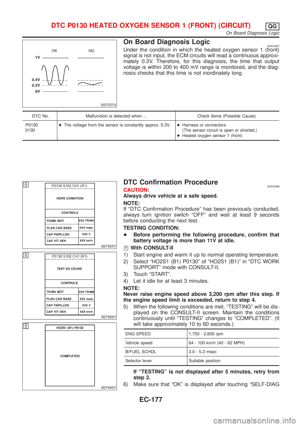
SEF237U
On Board Diagnosis LogicNJEC0097Under the condition in which the heated oxygen sensor 1 (front)
signal is not input, the ECM circuits will read a continuous approxi-
mately 0.3V. Therefore, for this diagnosis, the time that output
voltage is within 200 to 400 mV range is monitored, and the diag-
nosis checks that this time is not inordinately long.
DTC No. Malfunction is detected when ... Check Items (Possible Cause)
P0130
0130+The voltage from the sensor is constantly approx. 0.3V.+Harness or connectors
(The sensor circuit is open or shorted.)
+Heated oxygen sensor 1 (front)
SEF825Y
SEF826Y
SEF645Y
DTC Confirmation ProcedureNJEC0098CAUTION:
Always drive vehicle at a safe speed.
NOTE:
If ªDTC Confirmation Procedureº has been previously conducted,
always turn ignition switch ªOFFº and wait at least 9 seconds
before conducting the next test.
TESTING CONDITION:
+Before performing the following procedure, confirm that
battery voltage is more than 11V at idle.
With CONSULT-II
1) Start engine and warm it up to normal operating temperature.
2) Select ªHO2S1 (B1) P0130º of ªHO2S1 (B1)º in ªDTC WORK
SUPPORTº mode with CONSULT-II.
3) Touch ªSTARTº.
4) Let it idle for at least 3 minutes.
NOTE:
Never raise engine speed above 3,200 rpm after this step. If
the engine speed limit is exceeded, return to step 4.
5) When the following conditions are met, ªTESTINGº will be dis-
played on the CONSULT-II screen. Maintain the conditions
continuously until ªTESTINGº changes to ªCOMPLETEDº. (It
will take approximately 10 to 60 seconds.)
ENG SPEED 1,700 - 2,600 rpm
Vehicle speed 64 - 100 km/h (40 - 62 MPH)
B/FUEL SCHDL 3.0 - 5.2 msec
Selector lever Suitable position
If ªTESTINGº is not displayed after 5 minutes, retry from
step 2.
6) Make sure that ªOKº is displayed after touching ªSELF-DIAG
DTC P0130 HEATED OXYGEN SENSOR 1 (FRONT) (CIRCUIT)QG
On Board Diagnosis Logic
EC-177