2001 NISSAN ALMERA N16 turn signal
[x] Cancel search: turn signalPage 476 of 2493

Diagnostic ProcedureNJEC0101
1 INSPECTION START
1. Turn ignition switch ªOFFº.
2. Loosen and retighten engine ground screws.
JEF104Y
3. Disconnect heated oxygen sensor 1 (front) harness connector.
SEF012XA
©GO TO 2.
2 CHECK INPUT SIGNAL CIRCUIT
1. Disconnect ECM harness connector.
2. Check harness continuity between ECM terminal 62 and heated oxygen sensor 1 (front) harness connector terminal 2.
Refer to wiring diagram.
Continuity should exist.
3. Check harness continuity between ECM terminal 62 (or terminal 2) and ground.
Continuity should not exist.
4. Also check harness for short to power.
OK or NG
OK©GO TO 3.
NG©Repair open circuit or short to ground or short to power in harness or connectors.
3 CHECK HEATED OXYGEN SENSOR 1 (FRONT)
Refer to ªComponent Inspectionº, EC-181.
OK or NG
OK©GO TO 4.
NG©Replace heated oxygen sensor 1 (front).
4 CHECK INTERMITTENT INCIDENT
Perform ªTROUBLE DIAGNOSIS FOR INTERMITTENT INCIDENTº, EC-144.
©INSPECTION END
DTC P0130 HEATED OXYGEN SENSOR 1 (FRONT) (CIRCUIT)QG
Diagnostic Procedure
EC-180
Page 492 of 2493
SEF010V
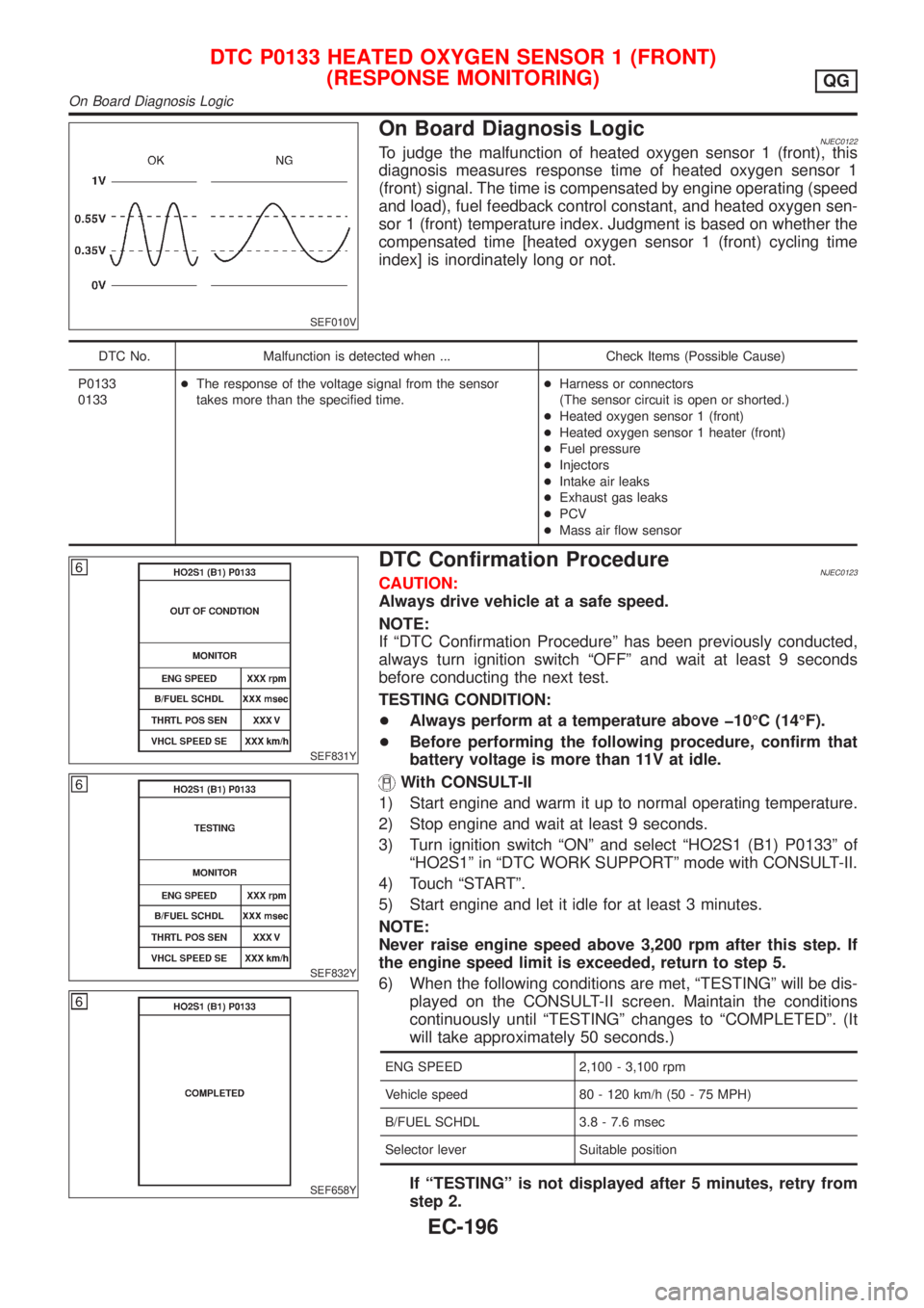
On Board Diagnosis LogicNJEC0122To judge the malfunction of heated oxygen sensor 1 (front), this
diagnosis measures response time of heated oxygen sensor 1
(front) signal. The time is compensated by engine operating (speed
and load), fuel feedback control constant, and heated oxygen sen-
sor 1 (front) temperature index. Judgment is based on whether the
compensated time [heated oxygen sensor 1 (front) cycling time
index] is inordinately long or not.
DTC No. Malfunction is detected when ... Check Items (Possible Cause)
P0133
0133+The response of the voltage signal from the sensor
takes more than the specified time.+Harness or connectors
(The sensor circuit is open or shorted.)
+Heated oxygen sensor 1 (front)
+Heated oxygen sensor 1 heater (front)
+Fuel pressure
+Injectors
+Intake air leaks
+Exhaust gas leaks
+PCV
+Mass air flow sensor
SEF831Y
SEF832Y
SEF658Y
DTC Confirmation ProcedureNJEC0123CAUTION:
Always drive vehicle at a safe speed.
NOTE:
If ªDTC Confirmation Procedureº has been previously conducted,
always turn ignition switch ªOFFº and wait at least 9 seconds
before conducting the next test.
TESTING CONDITION:
+Always perform at a temperature above þ10ÉC (14ÉF).
+Before performing the following procedure, confirm that
battery voltage is more than 11V at idle.
With CONSULT-II
1) Start engine and warm it up to normal operating temperature.
2) Stop engine and wait at least 9 seconds.
3) Turn ignition switch ªONº and select ªHO2S1 (B1) P0133º of
ªHO2S1º in ªDTC WORK SUPPORTº mode with CONSULT-II.
4) Touch ªSTARTº.
5) Start engine and let it idle for at least 3 minutes.
NOTE:
Never raise engine speed above 3,200 rpm after this step. If
the engine speed limit is exceeded, return to step 5.
6) When the following conditions are met, ªTESTINGº will be dis-
played on the CONSULT-II screen. Maintain the conditions
continuously until ªTESTINGº changes to ªCOMPLETEDº. (It
will take approximately 50 seconds.)
ENG SPEED 2,100 - 3,100 rpm
Vehicle speed 80 - 120 km/h (50 - 75 MPH)
B/FUEL SCHDL 3.8 - 7.6 msec
Selector lever Suitable position
If ªTESTINGº is not displayed after 5 minutes, retry from
step 2.
DTC P0133 HEATED OXYGEN SENSOR 1 (FRONT)
(RESPONSE MONITORING)
QG
On Board Diagnosis Logic
EC-196
Page 496 of 2493
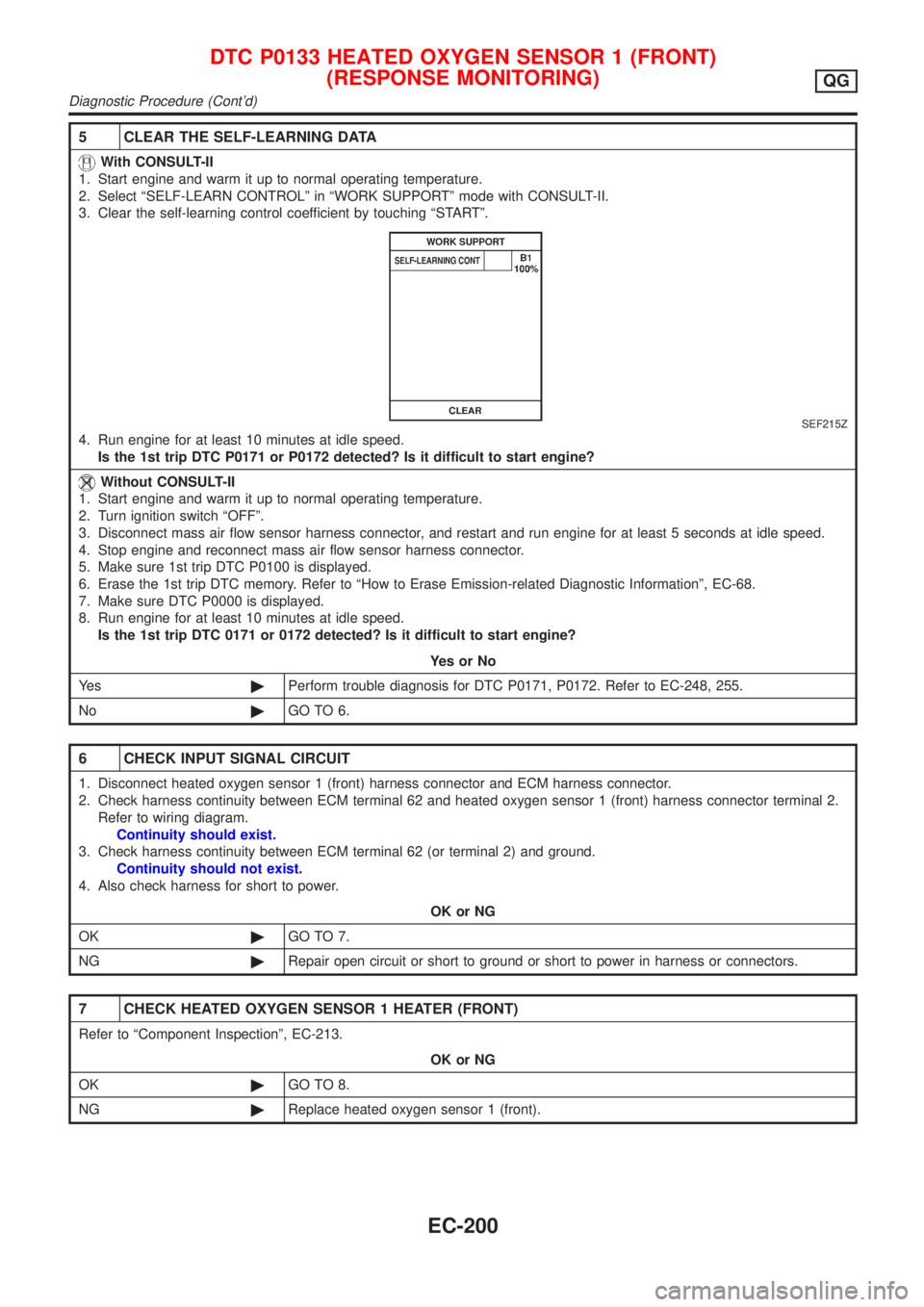
5 CLEAR THE SELF-LEARNING DATA
With CONSULT-II
1. Start engine and warm it up to normal operating temperature.
2. Select ªSELF-LEARN CONTROLº in ªWORK SUPPORTº mode with CONSULT-II.
3. Clear the self-learning control coefficient by touching ªSTARTº.
SEF215Z
4. Run engine for at least 10 minutes at idle speed.
Is the 1st trip DTC P0171 or P0172 detected? Is it difficult to start engine?
Without CONSULT-II
1. Start engine and warm it up to normal operating temperature.
2. Turn ignition switch ªOFFº.
3. Disconnect mass air flow sensor harness connector, and restart and run engine for at least 5 seconds at idle speed.
4. Stop engine and reconnect mass air flow sensor harness connector.
5. Make sure 1st trip DTC P0100 is displayed.
6. Erase the 1st trip DTC memory. Refer to ªHow to Erase Emission-related Diagnostic Informationº, EC-68.
7. Make sure DTC P0000 is displayed.
8. Run engine for at least 10 minutes at idle speed.
Is the 1st trip DTC 0171 or 0172 detected? Is it difficult to start engine?
YesorNo
Ye s©Perform trouble diagnosis for DTC P0171, P0172. Refer to EC-248, 255.
No©GO TO 6.
6 CHECK INPUT SIGNAL CIRCUIT
1. Disconnect heated oxygen sensor 1 (front) harness connector and ECM harness connector.
2. Check harness continuity between ECM terminal 62 and heated oxygen sensor 1 (front) harness connector terminal 2.
Refer to wiring diagram.
Continuity should exist.
3. Check harness continuity between ECM terminal 62 (or terminal 2) and ground.
Continuity should not exist.
4. Also check harness for short to power.
OK or NG
OK©GO TO 7.
NG©Repair open circuit or short to ground or short to power in harness or connectors.
7 CHECK HEATED OXYGEN SENSOR 1 HEATER (FRONT)
Refer to ªComponent Inspectionº, EC-213.
OK or NG
OK©GO TO 8.
NG©Replace heated oxygen sensor 1 (front).
DTC P0133 HEATED OXYGEN SENSOR 1 (FRONT)
(RESPONSE MONITORING)
QG
Diagnostic Procedure (Cont'd)
EC-200
Page 515 of 2493

3 CHECK INPUT SIGNAL CIRCUIT
1. Turn ignition switch ªOFFº.
2. Disconnect heated oxygen sensor 2 (rear) harness connector and ECM harness connector.
NEF345A
3. Check harness continuity between ECM terminal 63 and heated oxygen sensor 2 (rear) harness connector terminal 1.
Refer to wiring diagram.
Continuity should exist.
4. Check harness continuity between ECM terminal 63 [or heated oxygen sensor 2 (rear) harness connector terminal 1]
and ground.
Continuity should not exist.
5. Also check harness for short to ground and short to power.
OK or NG
OK©GO TO 5.
NG©GO TO 4.
4 DETECT MALFUNCTIONING PART
Check the harness for open or short between heated oxygen sensor 2 (rear) and ECM.
©Repair open circuit or short to ground or short to power in harness or connectors.
5 CHECK GROUND CIRCUIT
1. Check harness continuity between heated oxygen sensor 2 (rear) harness connector terminal 4 and body ground.
Refer to wiring diagram.
Continuity should exist.
2. Also check harness for short to ground and short to power.
OK or NG
OK©GO TO 6.
NG©Repair open circuit or short to ground or short to power in harness or connectors.
6 CHECK HEATED OXYGEN SENSOR 2 (REAR)
Refer to ªComponent Inspectionº, EC-220.
OK or NG
OK©GO TO 7.
NG©Replace heated oxygen sensor 2 (rear).
7 CHECK INTERMITTENT INCIDENT
Perform ªTROUBLE DIAGNOSIS FOR INTERMITTENT INCIDENTº, EC-144.
©INSPECTION END
DTC P0137 HEATED OXYGEN SENSOR 2 (REAR) (MIN. VOLTAGE
MONITORING)
QG
Diagnostic Procedure (Cont'd)
EC-219
Page 536 of 2493
Diagnostic ProcedureNJEC0178
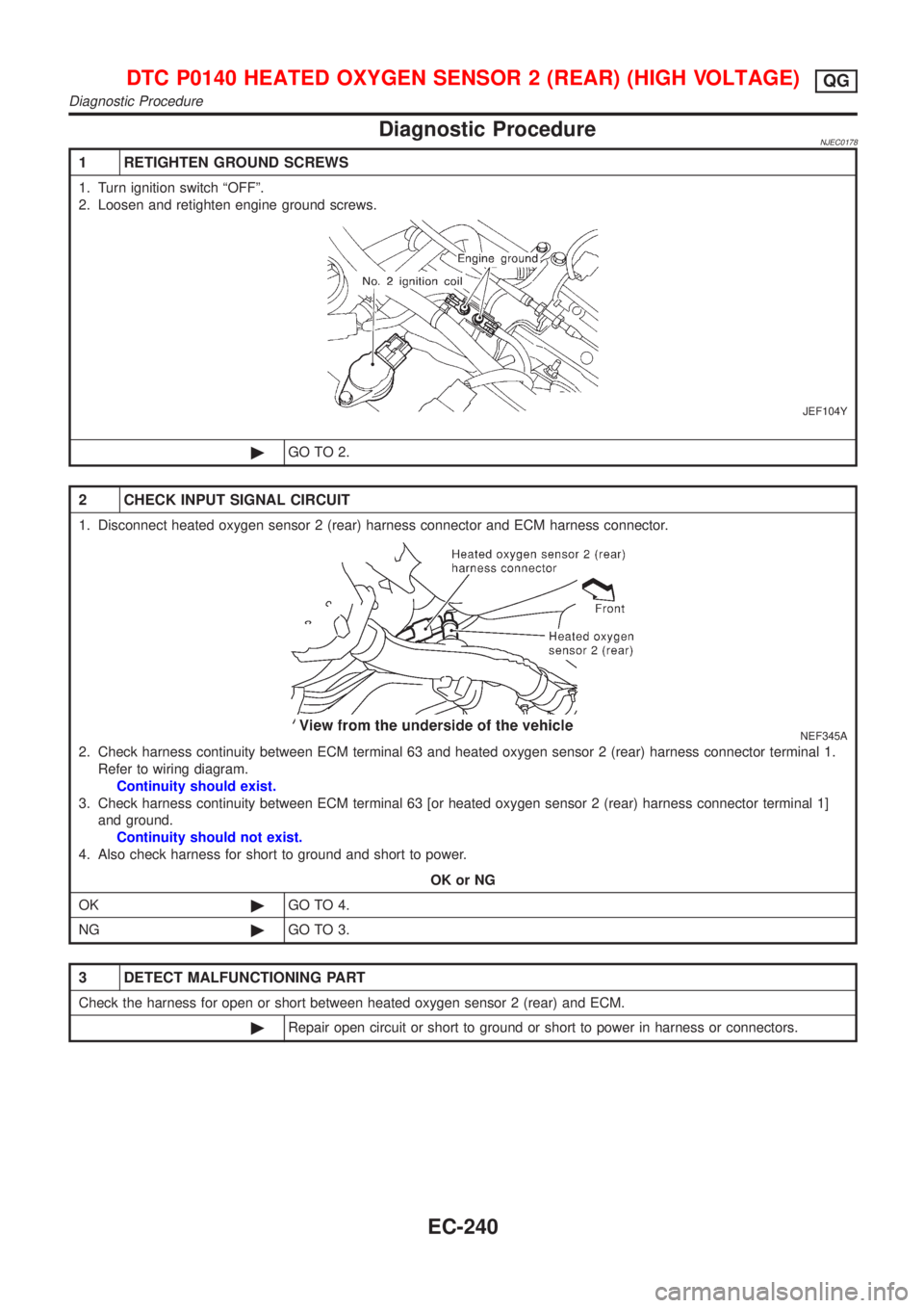
1 RETIGHTEN GROUND SCREWS
1. Turn ignition switch ªOFFº.
2. Loosen and retighten engine ground screws.
JEF104Y
©GO TO 2.
2 CHECK INPUT SIGNAL CIRCUIT
1. Disconnect heated oxygen sensor 2 (rear) harness connector and ECM harness connector.
NEF345A
2. Check harness continuity between ECM terminal 63 and heated oxygen sensor 2 (rear) harness connector terminal 1.
Refer to wiring diagram.
Continuity should exist.
3. Check harness continuity between ECM terminal 63 [or heated oxygen sensor 2 (rear) harness connector terminal 1]
and ground.
Continuity should not exist.
4. Also check harness for short to ground and short to power.
OK or NG
OK©GO TO 4.
NG©GO TO 3.
3 DETECT MALFUNCTIONING PART
Check the harness for open or short between heated oxygen sensor 2 (rear) and ECM.
©Repair open circuit or short to ground or short to power in harness or connectors.
DTC P0140 HEATED OXYGEN SENSOR 2 (REAR) (HIGH VOLTAGE)QG
Diagnostic Procedure
EC-240
Page 540 of 2493

On Board Diagnosis LogicNJEC0183
DTC No. Malfunction is detected when ... Check Items (Possible Cause)
P0141
0141+The current amperage in the heated oxygen sensor 2
heater (rear) circuit is out of the normal range.
[An improper voltage drop signal is sent to ECM through
the heated oxygen sensor 2 heater (rear).]+Harness or connectors
(The heated oxygen sensor 2 heater (rear) cir-
cuit is open or shorted.)
+Heated oxygen sensor 2 heater (rear)
DTC Confirmation ProcedureNJEC0184NOTE:
If ªDTC Confirmation Procedure º has been previously conducted,
always turn ignition switch ªOFFº and wait at least 9 seconds
before conducting the next test.
TESTING CONDITION:
Before performing the following procedure, confirm that bat-
tery voltage is in between 10.5V and 16V at idle.
SEF175Y
With CONSULT-II
1) Turn ignition switch ªONº and select ªDATA MONITORº mode
with CONSULT-II.
2) Start engine and drive vehicle at a speed of more than 70 km/h
(43 MPH) for 2 consecutive minutes. Engine speed must be
maintained at speeds of 3,600 rpm or less during vehicle
operations.
3) If 1st trip DTC is detected, go to ªDiagnostic Procedureº,
EC-246.
With GST
1) Start engine and drive vehicle at a speed of more than 70 km/h
(43 MPH) for 2 consecutive minutes. Engine speed must be
maintained at speeds of 3,600 rpm or less during vehicle
operations.
2) Turn ignition switch ªOFFº and wait at least 9 seconds.
3) Start engine and drive vehicle at a speed of more than 70 km/h
(43 MPH) for 2 consecutive minutes.
4) Select ªMODE 3º with GST.
5) If DTC is detected, go to ªDiagnostic Procedureº, EC-246.
When using GST, ªDTC Confirmation Procedure º should be
performed twice as much as when using CONSULT-II because
GST cannot display MODE 7 (1st trip DTC) concerning this
diagnosis. Therefore, using CONSULT-II is recommended.
DTC P0141 HEATED OXYGEN SENSOR 2 HEATER (REAR)QG
On Board Diagnosis Logic
EC-244
Page 544 of 2493
On Board Diagnosis LogicNJEC0188With the Air/Fuel Mixture Ratio Self-Learning Control, the actual mixture ratio can be brought closely to the
theoretical mixture ratio based on the mixture ratio feedback signal from the heated oxygen sensor 1 (front).
The ECM calculates the necessary compensation to correct the offset between the actual and the theoretical
ratios.
In case the amount of the compensation value is extremely large (The actual mixture ratio is too lean.), the
ECM judges the condition as the fuel injection system malfunction and lights up the MIL (2 trip detection logic).
Sensor Input Signal to ECMECM func-
tionActuator
Heated oxygen sensor 1 (front)Density of oxygen in exhaust gas
(Mixture ratio feedback signal)Fuel injec-
tion & mix-
ture ratio
controlInjectors
DTC No. Malfunction is detected when ... Check Items (Possible Cause)
P0171
0171+Fuel injection system does not operate properly.
+The amount of mixture ratio compensation is too large.
(The mixture ratio is too lean.)+Intake air leaks
+Heated oxygen sensor 1 (front)
+Injectors
+Exhaust gas leaks
+Incorrect fuel pressure
+Lack of fuel
+Mass air flow sensor
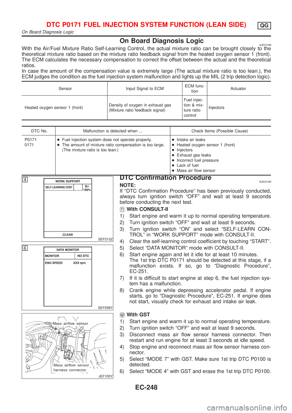
SEF215Z
SEF058Y
DTC Confirmation ProcedureNJEC0189NOTE:
If ªDTC Confirmation Procedureº has been previously conducted,
always turn ignition switch ªOFFº and wait at least 9 seconds
before conducting the next test.
With CONSULT-II
1) Start engine and warm it up to normal operating temperature.
2) Turn ignition switch ªOFFº and wait at least 9 seconds.
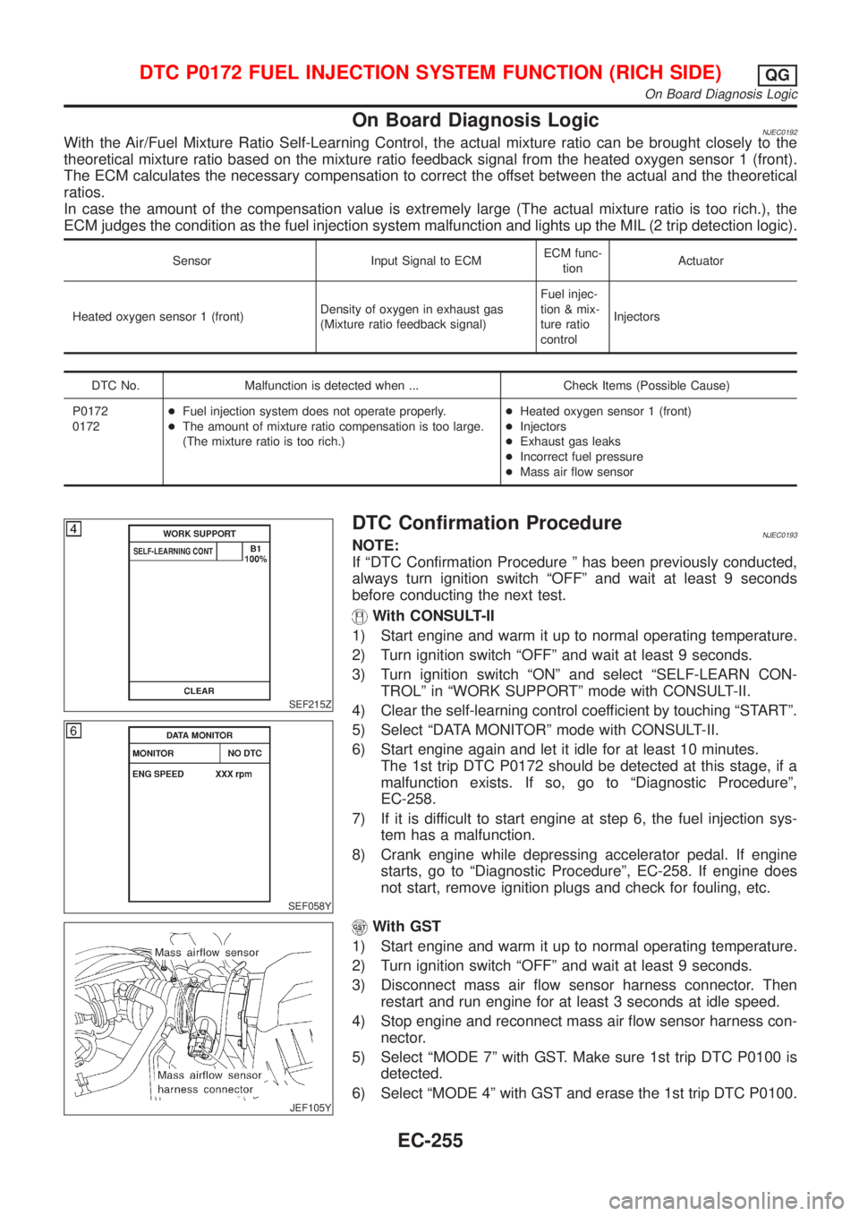
3) Turn ignition switch ªONº and select ªSELF-LEARN CON-
TROLº in ªWORK SUPPORTº mode with CONSULT-II.
4) Clear the self-learning control coefficient by touching ªSTARTº.
5) Select ªDATA MONITORº mode with CONSULT-II.
6) Start engine again and let it idle for at least 10 minutes.
The 1st trip DTC P0171 should be detected at this stage, if a
malfunction exists. If so, go to ªDiagnostic Procedureº,
EC-251.
7) If it is difficult to start engine at step 6, the fuel injection sys-
tem has a malfunction.
8) Crank engine while depressing accelerator pedal. If engine
starts, go to ªDiagnostic Procedureº, EC-251. If engine does
not start, visually check for exhaust and intake air leak.
JEF105Y
With GST
1) Start engine and warm it up to normal operating temperature.
2) Turn ignition switch ªOFFº and wait at least 9 seconds.
3) Disconnect mass air flow sensor harness connector. Then
restart and run engine for at least 3 seconds at idle speed.
4) Stop engine and reconnect mass air flow sensor harness con-
nector.
5) Select ªMODE 7º with GST. Make sure 1st trip DTC P0100 is
detected.
6) Select ªMODE 4º with GST and erase the 1st trip DTC P0100.
DTC P0171 FUEL INJECTION SYSTEM FUNCTION (LEAN SIDE)QG
On Board Diagnosis Logic
EC-248
Page 551 of 2493
On Board Diagnosis LogicNJEC0192With the Air/Fuel Mixture Ratio Self-Learning Control, the actual mixture ratio can be brought closely to the
theoretical mixture ratio based on the mixture ratio feedback signal from the heated oxygen sensor 1 (front).
The ECM calculates the necessary compensation to correct the offset between the actual and the theoretical
ratios.
In case the amount of the compensation value is extremely large (The actual mixture ratio is too rich.), the
ECM judges the condition as the fuel injection system malfunction and lights up the MIL (2 trip detection logic).
Sensor Input Signal to ECMECM func-
tionActuator
Heated oxygen sensor 1 (front)Density of oxygen in exhaust gas
(Mixture ratio feedback signal)Fuel injec-
tion & mix-
ture ratio
controlInjectors
DTC No. Malfunction is detected when ... Check Items (Possible Cause)
P0172
0172+Fuel injection system does not operate properly.
+The amount of mixture ratio compensation is too large.
(The mixture ratio is too rich.)+Heated oxygen sensor 1 (front)
+Injectors
+Exhaust gas leaks
+Incorrect fuel pressure
+Mass air flow sensor
SEF215Z
SEF058Y
DTC Confirmation ProcedureNJEC0193NOTE:
If ªDTC Confirmation Procedure º has been previously conducted,
always turn ignition switch ªOFFº and wait at least 9 seconds
before conducting the next test.
With CONSULT-II
1) Start engine and warm it up to normal operating temperature.
2) Turn ignition switch ªOFFº and wait at least 9 seconds.
3) Turn ignition switch ªONº and select ªSELF-LEARN CON-
TROLº in ªWORK SUPPORTº mode with CONSULT-II.
4) Clear the self-learning control coefficient by touching ªSTARTº.
5) Select ªDATA MONITORº mode with CONSULT-II.
6) Start engine again and let it idle for at least 10 minutes.
The 1st trip DTC P0172 should be detected at this stage, if a
malfunction exists. If so, go to ªDiagnostic Procedureº,
EC-258.
7) If it is difficult to start engine at step 6, the fuel injection sys-
tem has a malfunction.
8) Crank engine while depressing accelerator pedal. If engine
starts, go to ªDiagnostic Procedureº, EC-258. If engine does
not start, remove ignition plugs and check for fouling, etc.
JEF105Y
With GST
1) Start engine and warm it up to normal operating temperature.
2) Turn ignition switch ªOFFº and wait at least 9 seconds.
3) Disconnect mass air flow sensor harness connector. Then
restart and run engine for at least 3 seconds at idle speed.
4) Stop engine and reconnect mass air flow sensor harness con-
nector.
5) Select ªMODE 7º with GST. Make sure 1st trip DTC P0100 is
detected.
6) Select ªMODE 4º with GST and erase the 1st trip DTC P0100.
DTC P0172 FUEL INJECTION SYSTEM FUNCTION (RICH SIDE)QG
On Board Diagnosis Logic
EC-255