2001 NISSAN ALMERA N16 charging
[x] Cancel search: chargingPage 760 of 2493

System DescriptionNJEC0444
Sensor Input Signal to ECMECM func-
tionActuator
Crankshaft position sensor (POS) Engine speed
Fuel pump
controlFuel pump relay Camshaft position sensor (PHASE) Engine speed and cylinder number
Ignition switch Ignition signal and start signal
The ECM activates the fuel pump for several seconds after the ignition switch is turned on to improve engine
startability. If the ECM receives a 180É signal from the camshaft position sensor, it knows that the engine is
rotating, and causes the pump to perform. If the 180É signal is not received when the ignition switch is on, the
engine stalls. The ECM stops pump operation and prevents battery discharging, thereby improving safety. The
ECM does not directly drive the fuel pump. It controls the ON/OFF fuel pump relay, which in turn controls the
fuel pump.
Condition Fuel pump operation
Ignition switch is turned to ON. Operates for 1 second
Engine running and cranking Operates
When engine is stopped (Signal is not sent from crankshaft position sensor
and camshaft position sensor.)Stops in 1.5 seconds
Except as shown aboveStops
SEF605X
Component DescriptionNJEC0501A turbine type design fuel pump is used in the fuel tank.
CONSULT-II Reference Value in Data Monitor
Mode
NJEC0445
MONITOR ITEM CONDITION SPECIFICATION
FUEL PUMP RLY+Ignition switch is turned to ON (Operates for 1 second)
+Engine running and cranking
+When engine is stopped (stops in 1.5 seconds)ON
+Except as shown above OFF
FUEL PUMPQG
System Description
EC-464
Page 1201 of 2493
SMA827CA
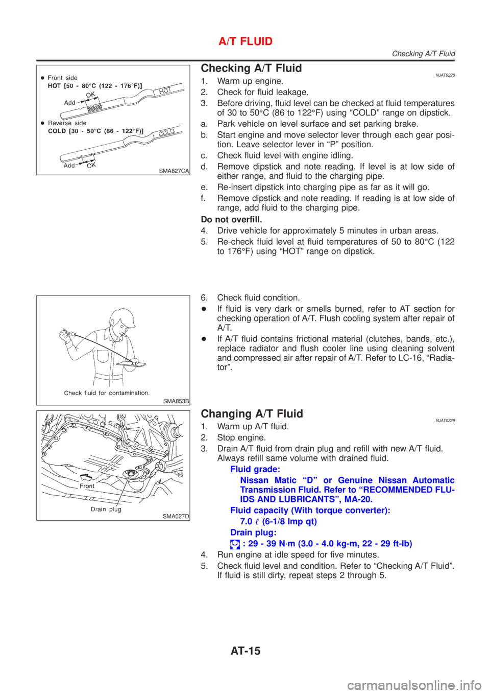
Checking A/T FluidNJAT02281. Warm up engine.
2. Check for fluid leakage.
3. Before driving, fluid level can be checked at fluid temperatures
of 30 to 50ÉC (86 to 122ÉF) using ªCOLDº range on dipstick.
a. Park vehicle on level surface and set parking brake.
b. Start engine and move selector lever through each gear posi-
tion. Leave selector lever in ªPº position.
c. Check fluid level with engine idling.
d. Remove dipstick and note reading. If level is at low side of
either range, and fluid to the charging pipe.
e. Re-insert dipstick into charging pipe as far as it will go.
f. Remove dipstick and note reading. If reading is at low side of
range, add fluid to the charging pipe.
Do not overfill.
4. Drive vehicle for approximately 5 minutes in urban areas.
5. Re-check fluid level at fluid temperatures of 50 to 80ÉC (122
to 176ÉF) using ªHOTº range on dipstick.
SMA853B
6. Check fluid condition.
+If fluid is very dark or smells burned, refer to AT section for
checking operation of A/T. Flush cooling system after repair of
A/T.
+If A/T fluid contains frictional material (clutches, bands, etc.),
replace radiator and flush cooler line using cleaning solvent
and compressed air after repair of A/T. Refer to LC-16, ªRadia-
torº.
SMA027D
Changing A/T FluidNJAT02291. Warm up A/T fluid.
2. Stop engine.
3. Drain A/T fluid from drain plug and refill with new A/T fluid.
Always refill same volume with drained fluid.
Fluid grade:
Nissan Matic ªDº or Genuine Nissan Automatic
Transmission Fluid. Refer to ªRECOMMENDED FLU-
IDS AND LUBRICANTSº, MA-20.
Fluid capacity (With torque converter):
7.0!(6-1/8 Imp qt)
Drain plug:
: 29 - 39 N´m (3.0 - 4.0 kg-m, 22 - 29 ft-lb)
4. Run engine at idle speed for five minutes.
5. Check fluid level and condition. Refer to ªChecking A/T Fluidº.
If fluid is still dirty, repeat steps 2 through 5.
A/T FLUID
Checking A/T Fluid
AT-15
Page 1300 of 2493
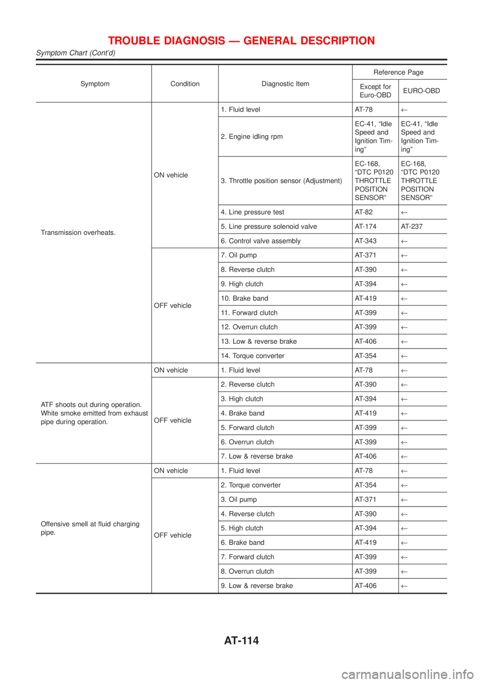
Symptom Condition Diagnostic ItemReference Page
Except for
Euro-OBDEURO-OBD
Transmission overheats.ON vehicle1. Fluid level AT-78¬
2. Engine idling rpmEC-41, ªIdle
Speed and
Ignition Tim-
ingºEC-41, ªIdle
Speed and
Ignition Tim-
ingº
3. Throttle position sensor (Adjustment)EC-168,
ªDTC P0120
THROTTLE
POSITION
SENSORºEC-168,
ªDTC P0120
THROTTLE
POSITION
SENSORº
4. Line pressure test AT-82¬
5. Line pressure solenoid valve AT-174 AT-237
6. Control valve assembly AT-343¬
OFF vehicle7. Oil pump AT-371¬
8. Reverse clutch AT-390¬
9. High clutch AT-394¬
10. Brake band AT-419¬
11. Forward clutch AT-399¬
12. Overrun clutch AT-399¬
13. Low & reverse brake AT-406¬
14. Torque converter AT-354¬
ATF shoots out during operation.
White smoke emitted from exhaust
pipe during operation.ON vehicle 1. Fluid level AT-78¬
OFF vehicle2. Reverse clutch AT-390¬
3. High clutch AT-394¬
4. Brake band AT-419¬
5. Forward clutch AT-399¬
6. Overrun clutch AT-399¬
7. Low & reverse brake AT-406¬
Offensive smell at fluid charging
pipe.ON vehicle 1. Fluid level AT-78¬
OFF vehicle2. Torque converter AT-354¬
3. Oil pump AT-371¬
4. Reverse clutch AT-390¬
5. High clutch AT-394¬
6. Brake band AT-419¬
7. Forward clutch AT-399¬
8. Overrun clutch AT-399¬
9. Low & reverse brake AT-406¬
TROUBLE DIAGNOSIS Ð GENERAL DESCRIPTION
Symptom Chart (Cont'd)
AT-114
Page 1540 of 2493
NJAT0120
SAT049K
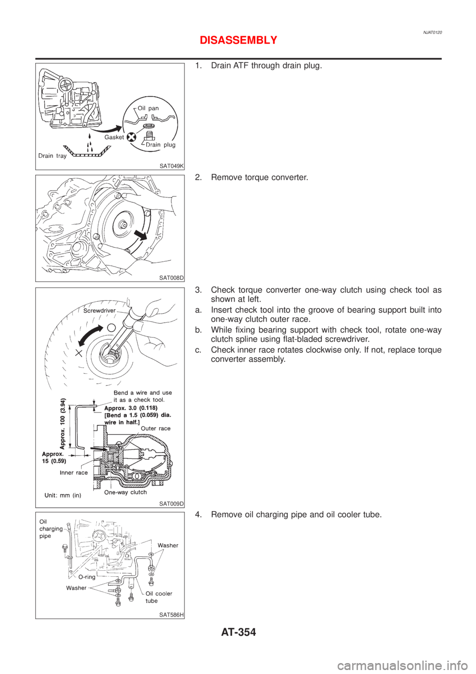
1. Drain ATF through drain plug.
SAT008D
2. Remove torque converter.
SAT009D
3. Check torque converter one-way clutch using check tool as
shown at left.
a. Insert check tool into the groove of bearing support built into
one-way clutch outer race.
b. While fixing bearing support with check tool, rotate one-way
clutch spline using flat-bladed screwdriver.
c. Check inner race rotates clockwise only. If not, replace torque
converter assembly.
SAT586H
4. Remove oil charging pipe and oil cooler tube.
DISASSEMBLY
AT-354
Page 1634 of 2493
SAT426DB
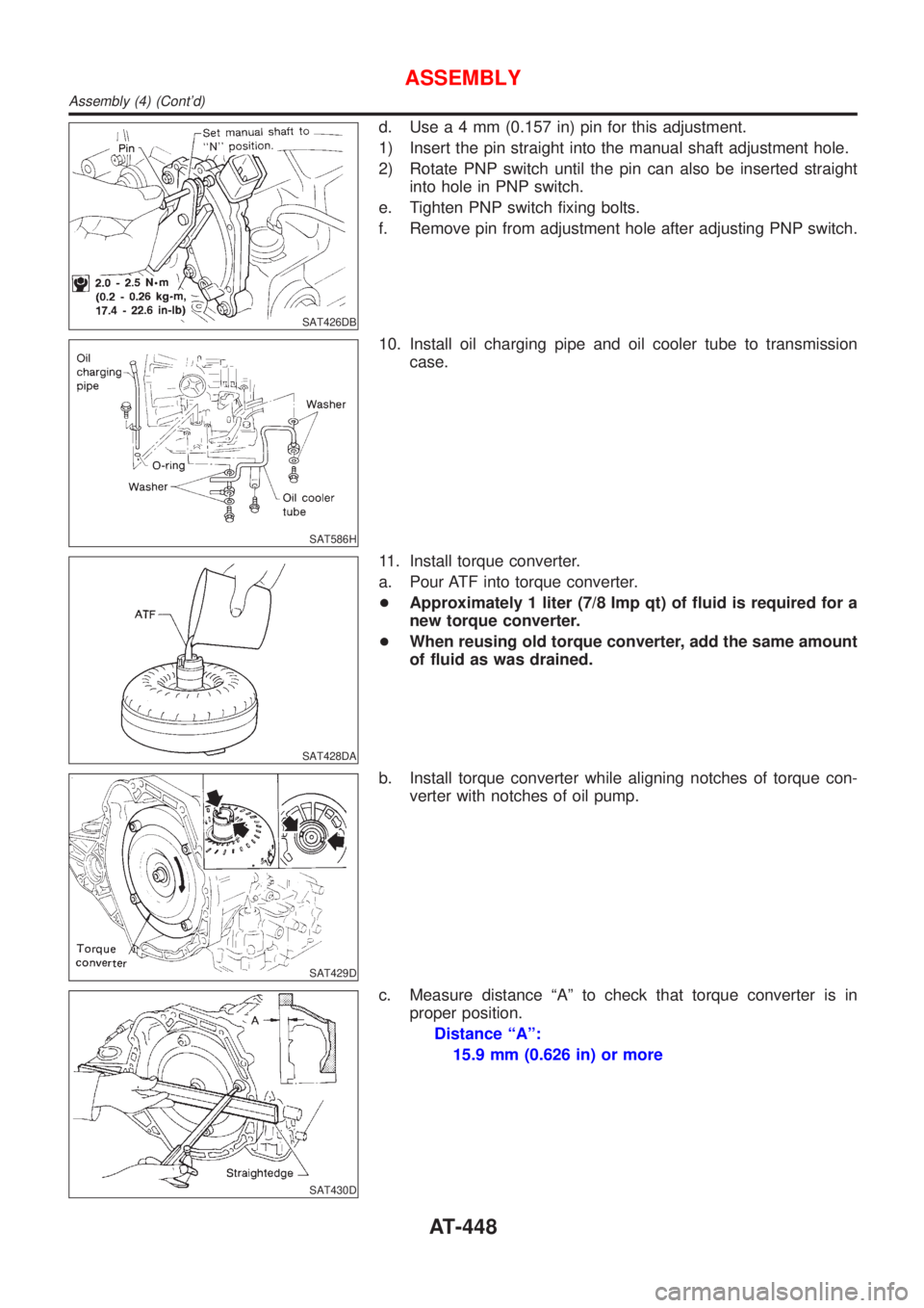
d. Usea4mm(0.157 in) pin for this adjustment.
1) Insert the pin straight into the manual shaft adjustment hole.
2) Rotate PNP switch until the pin can also be inserted straight
into hole in PNP switch.
e. Tighten PNP switch fixing bolts.
f. Remove pin from adjustment hole after adjusting PNP switch.
SAT586H
10. Install oil charging pipe and oil cooler tube to transmission
case.
SAT428DA
11. Install torque converter.
a. Pour ATF into torque converter.
+Approximately 1 liter (7/8 Imp qt) of fluid is required for a
new torque converter.
+When reusing old torque converter, add the same amount
of fluid as was drained.
SAT429D
b. Install torque converter while aligning notches of torque con-
verter with notches of oil pump.
SAT430D
c. Measure distance ªAº to check that torque converter is in
proper position.
Distance ªAº:
15.9 mm (0.626 in) or more
ASSEMBLY
Assembly (4) (Cont'd)
AT-448
Page 1873 of 2493
![NISSAN ALMERA N16 2001 Electronic Repair Manual Diagnostic item ExplanationRepair order
Recheck SRS at each
replacement.
SATELLITE SENS RH
[UNIT FAIL]
SATELLITE SENS RH
[COMM FAIL]+RH side air bag (satellite) sensor 1. Visually check the wiring
har NISSAN ALMERA N16 2001 Electronic Repair Manual Diagnostic item ExplanationRepair order
Recheck SRS at each
replacement.
SATELLITE SENS RH
[UNIT FAIL]
SATELLITE SENS RH
[COMM FAIL]+RH side air bag (satellite) sensor 1. Visually check the wiring
har](/manual-img/5/57351/w960_57351-1872.png)
Diagnostic item ExplanationRepair order
Recheck SRS at each
replacement.
SATELLITE SENS RH
[UNIT FAIL]
SATELLITE SENS RH
[COMM FAIL]+RH side air bag (satellite) sensor 1. Visually check the wiring
harness connection.
2. Replace the harness if it
has visible damage.
3. Replace the RH side air
bag (satellite) sensor.
4. Replace the diagnosis sen-
sor unit.
5. Replace the related har-
ness.
PRE-TEN FRONT LH
[OPEN/VB-SHORT]+The circuit for the front LH pre-tensioner is open or shorted
to a power supply circuit.1. Visually check the wiring
harness connections.
2. Replace the harness if it
has visible damage.
3. Replace the front LH seat
belt.
(Before disposal, it must be
deactivated.)
4. Replace the diagnosis sen-
sor unit.
5. Replace the related har-
ness. PRE-TEN FRONT LH
[GND-SHORT]+The circuit for the front LH pre-tensioner is shorted to
ground.
PRE-TEN FRONT RH
[OPEN/VB-SHORT]+The circuit for the front RH pre-tensioner is open or shorted
to a power supply circuit.1. Visually check the wiring
harness connections.
2. Replace the harness if it
has visible damage.
3. Replace the front RH seat
belt.
(Before disposal, it must be
deactivated.)
4. Replace the diagnosis sen-
sor unit.
5. Replace the related har-
ness. PRE-TEN FRONT RH
[GND-SHORT]+The circuit for the front RH pre-tensioner is shorted to
ground.
CONTROL UNIT+Low battery voltage (Less than 9V)+Go to DIAGNOSTIC PRO-
CEDURE 3 (RS-54) after
charging battery.
+Diagnosis sensor unit is malfunctioning. 1. Visually check wiring har-
ness connections.
2. Replace the harness if it
has visible damage.
3. Replace diagnosis sensor
unit.
4. Replace the related har-
ness.
* Follow the procedures in numerical order when repairing malfunctioning parts. Confirm whether malfunction is eliminated
using the air bag or seat belt warning lamp or CONSULT-II each time repair is finished. If malfunction is still observed, pro-
ceed to the next step. When malfunction is eliminated, further repair work is not required.
SUPPLEMENTAL RESTRAINT SYSTEM (SRS)
Trouble Diagnoses with CONSULT-II (Cont'd)
RS-53
Page 1977 of 2493
+When installing an air conditioner in the vehicle, connect the pipes as the final stage of the opera-
tion. Do not remove the seal caps of pipes and other components until just before required for
connection.
+Allow components stored in cool areas to warm to working area temperature before removing seal
caps. This prevents condensation from forming inside A/C components.
+Thoroughly remove moisture from the refrigeration system before charging the refrigerant.
+Always replace used O-rings.
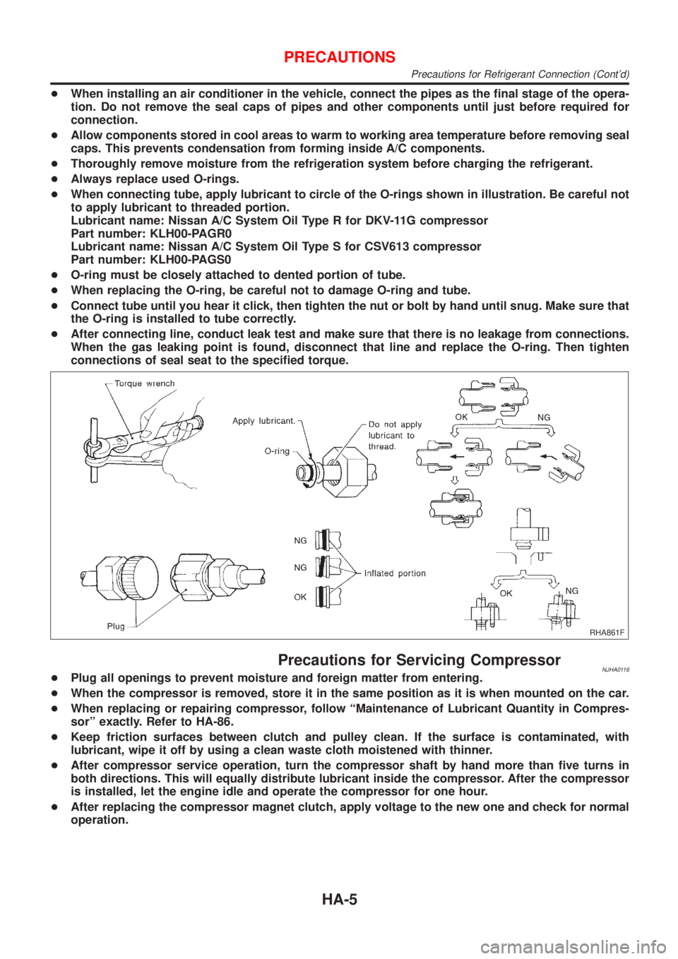
+When connecting tube, apply lubricant to circle of the O-rings shown in illustration. Be careful not
to apply lubricant to threaded portion.
Lubricant name: Nissan A/C System Oil Type R for DKV-11G compressor
Part number: KLH00-PAGR0
Lubricant name: Nissan A/C System Oil Type S for CSV613 compressor
Part number: KLH00-PAGS0
+O-ring must be closely attached to dented portion of tube.
+When replacing the O-ring, be careful not to damage O-ring and tube.
+Connect tube until you hear it click, then tighten the nut or bolt by hand until snug. Make sure that
the O-ring is installed to tube correctly.
+After connecting line, conduct leak test and make sure that there is no leakage from connections.
When the gas leaking point is found, disconnect that line and replace the O-ring. Then tighten
connections of seal seat to the specified torque.
RHA861F
Precautions for Servicing CompressorNJHA0116+Plug all openings to prevent moisture and foreign matter from entering.
+When the compressor is removed, store it in the same position as it is when mounted on the car.
+When replacing or repairing compressor, follow ªMaintenance of Lubricant Quantity in Compres-
sorº exactly. Refer to HA-86.
+Keep friction surfaces between clutch and pulley clean. If the surface is contaminated, with
lubricant, wipe it off by using a clean waste cloth moistened with thinner.
+After compressor service operation, turn the compressor shaft by hand more than five turns in
both directions. This will equally distribute lubricant inside the compressor. After the compressor
is installed, let the engine idle and operate the compressor for one hour.
+After replacing the compressor magnet clutch, apply voltage to the new one and check for normal
operation.
PRECAUTIONS
Precautions for Refrigerant Connection (Cont'd)
HA-5
Page 1979 of 2493
RHA273D
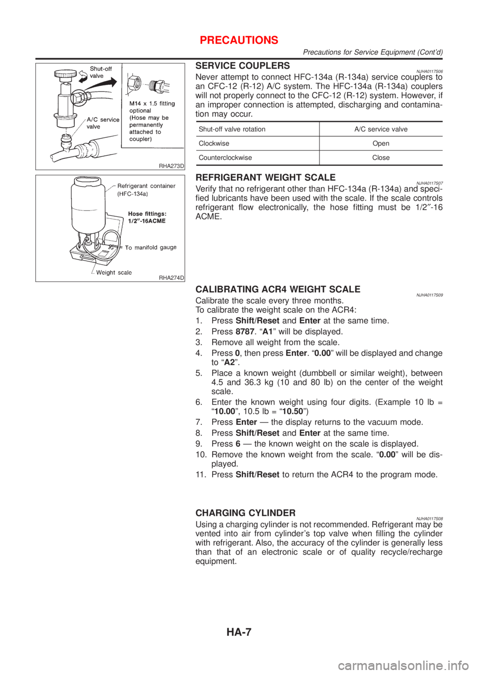
SERVICE COUPLERSNJHA0117S06Never attempt to connect HFC-134a (R-134a) service couplers to
an CFC-12 (R-12) A/C system. The HFC-134a (R-134a) couplers
will not properly connect to the CFC-12 (R-12) system. However, if
an improper connection is attempted, discharging and contamina-
tion may occur.
Shut-off valve rotation A/C service valve
Clockwise Open
Counterclockwise Close
RHA274D
REFRIGERANT WEIGHT SCALENJHA0117S07Verify that no refrigerant other than HFC-134a (R-134a) and speci-
fied lubricants have been used with the scale. If the scale controls
refrigerant flow electronically, the hose fitting must be 1/2²-16
ACME.
CALIBRATING ACR4 WEIGHT SCALENJHA0117S09Calibrate the scale every three months.
To calibrate the weight scale on the ACR4:
1. PressShift/ResetandEnterat the same time.
2. Press8787.ªA1º will be displayed.
3. Remove all weight from the scale.
4. Press0, then pressEnter.ª0.00º will be displayed and change
to ªA2º.
5. Place a known weight (dumbbell or similar weight), between
4.5 and 36.3 kg (10 and 80 lb) on the center of the weight
scale.
6. Enter the known weight using four digits. (Example 10 lb =
ª10.00º, 10.5 lb = ª10.50º)
7. PressEnterÐ the display returns to the vacuum mode.
8. PressShift/ResetandEnterat the same time.
9. Press6Ð the known weight on the scale is displayed.
10. Remove the known weight from the scale. ª0.00º will be dis-
played.
11. PressShift/Resetto return the ACR4 to the program mode.
CHARGING CYLINDERNJHA0117S08Using a charging cylinder is not recommended. Refrigerant may be
vented into air from cylinder's top valve when filling the cylinder
with refrigerant. Also, the accuracy of the cylinder is generally less
than that of an electronic scale or of quality recycle/recharge
equipment.
PRECAUTIONS
Precautions for Service Equipment (Cont'd)
HA-7