Page 2103 of 2493
ConstructionNJSC0012
MEL480HB
MEL141LC
CHARGING SYSTEM
Construction
SC-27
Page 2104 of 2493
MEL141LA
MEL142L
CHARGING SYSTEM
Construction (Cont'd)
SC-28
Page 2105 of 2493
MEL143LA
MEL144L
CHARGING SYSTEM
Construction (Cont'd)
SC-29
Page 2106 of 2493
MEL497L
MEL145L
Removal and InstallationNJSC0013REMOVAL (QG ENGINE)NJSC0013S011. Loosen drive belt idler pulley.
2. Remove drive belt idler pulley (include tightening screw).
3. Remove alternator harness.
4. Remove alternator upper bolt and lower bolt.
5. Remove alternator.
MEL948N
REMOVAL (YD ENGINE)NJSC0013S031. Remove alternator harness.
2. Loosen alternator upper nut and lower bolt.
3. Loosen drive belt.
4. Remove alternator bracket bolts (two).
5. Remove alternator upper nut and lower bolt.
6. Remove alternator.
CHARGING SYSTEM
Construction (Cont'd)
SC-30
Page 2107 of 2493
INSTALLATIONNJSC0013S02To install, reverse the removal procedure.
SEL032Z
DisassemblyNJSC0021REAR COVERNJSC0021S01CAUTION:
Rear cover may be hard to remove because a ring is used to
lock outer race of rear bearing. To facilitate removal of rear
cover, heat just bearing box section with a 200W soldering
iron.
Do not use a heat gun, as it can damage diode assembly.
REAR BEARINGNJSC0021S02CAUTION:
+Do not reuse rear bearing after removal. Replace with a
new one.
+Do not lubricate rear bearing outer race.
SEL033Z
InspectionNJSC0022ROTOR CHECKNJSC0022S011. Resistance test
Resistance: Refer to SDS (SC-35).
+Not within the specified values ... Replace rotor.
2. Insulator test
+Continuity exists ... Replace rotor.
3. Check slip ring for wear.
Slip ring minimum outer diameter:
Refer to SDS (SC-35).
+Not within the specified values ... Replace rotor.
CHARGING SYSTEM
Removal and Installation (Cont'd)
SC-31
Page 2108 of 2493
SEL034Z
BRUSH CHECKNJSC0022S021. Check smooth movement of brush.
+Not smooth ... Check brush holder and clean.
2. Check brush for wear.
+Replace brush if it is worn down to the limit line.
SEL037Z
STATOR CHECKNJSC0022S031. Continuity test
+No continuity ... Replace stator.
2. Ground test
+Continuity exists ... Replace stator.
SEL044Z
AssemblyNJSC0023RING FITTING IN REAR BEARINGNJSC0023S01+Fix ring into groove in rear bearing so that it is as close to the
adjacent area as possible.
CAUTION:
Do not reuse rear bearing after removal.
CHARGING SYSTEM
Inspection (Cont'd)
SC-32
Page 2109 of 2493
SEL048Z
SEL049Z
REAR COVER INSTALLATIONNJSC0023S021. Fit brush assembly, diode assembly, regulator assembly and
stator.
2. Push brushes up with fingers and install them to rotor.
Take care not to damage slip ring sliding surface.
CHARGING SYSTEM
Assembly (Cont'd)
SC-33
Page 2479 of 2493

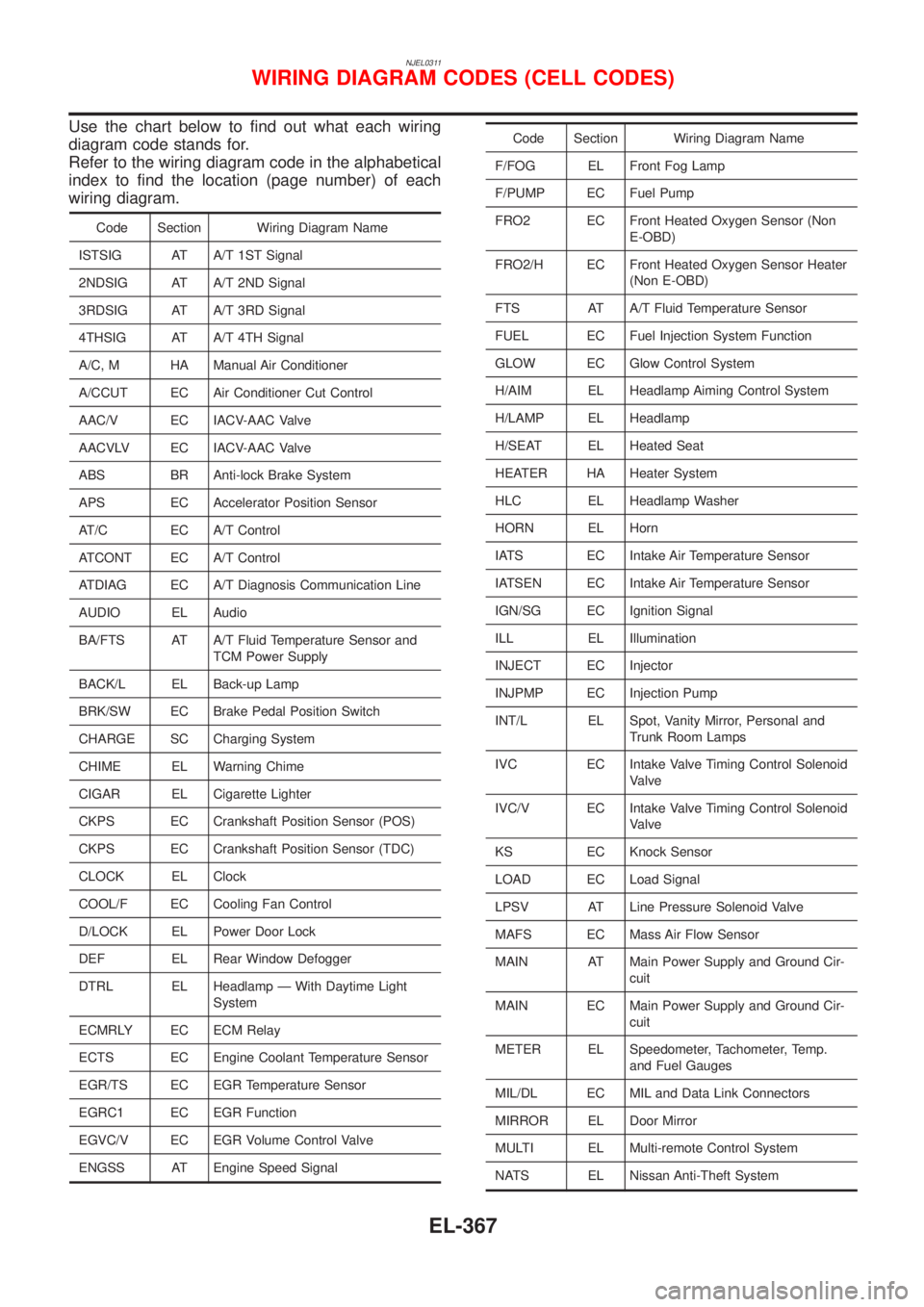
NJEL0311
Use the chart below to find out what each wiring
diagram code stands for.
Refer to the wiring diagram code in the alphabetical
index to find the location (page number) of each
wiring diagram.
Code Section Wiring Diagram Name
ISTSIG AT A/T 1ST Signal
2NDSIG AT A/T 2ND Signal
3RDSIG AT A/T 3RD Signal
4THSIG AT A/T 4TH Signal
A/C, M HA Manual Air Conditioner
A/CCUT EC Air Conditioner Cut Control
AAC/V EC IACV-AAC Valve
AACVLV EC IACV-AAC Valve
ABS BR Anti-lock Brake System
APS EC Accelerator Position Sensor
AT/C EC A/T Control
ATCONT EC A/T Control
ATDIAG EC A/T Diagnosis Communication Line
AUDIO EL Audio
BA/FTS AT A/T Fluid Temperature Sensor and
TCM Power Supply
BACK/L EL Back-up Lamp
BRK/SW EC Brake Pedal Position Switch
CHARGE SC Charging System
CHIME EL Warning Chime
CIGAR EL Cigarette Lighter
CKPS EC Crankshaft Position Sensor (POS)
CKPS EC Crankshaft Position Sensor (TDC)
CLOCK EL Clock
COOL/F EC Cooling Fan Control
D/LOCK EL Power Door Lock
DEF EL Rear Window Defogger
DTRL EL Headlamp Ð With Daytime Light
System
ECMRLY EC ECM Relay
ECTS EC Engine Coolant Temperature Sensor
EGR/TS EC EGR Temperature Sensor
EGRC1 EC EGR Function
EGVC/V EC EGR Volume Control Valve
ENGSS AT Engine Speed Signal
Code Section Wiring Diagram Name
F/FOG EL Front Fog Lamp
F/PUMP EC Fuel Pump
FRO2 EC Front Heated Oxygen Sensor (Non
E-OBD)
FRO2/H EC Front Heated Oxygen Sensor Heater
(Non E-OBD)
FTS AT A/T Fluid Temperature Sensor
FUEL EC Fuel Injection System Function
GLOW EC Glow Control System
H/AIM EL Headlamp Aiming Control System
H/LAMP EL Headlamp
H/SEAT EL Heated Seat
HEATER HA Heater System
HLC EL Headlamp Washer
HORN EL Horn
IATS EC Intake Air Temperature Sensor
IATSEN EC Intake Air Temperature Sensor
IGN/SG EC Ignition Signal
ILL EL Illumination
INJECT EC Injector
INJPMP EC Injection Pump
INT/L EL Spot, Vanity Mirror, Personal and
Trunk Room Lamps
IVC EC Intake Valve Timing Control Solenoid
Valve
IVC/V EC Intake Valve Timing Control Solenoid
Valve
KS EC Knock Sensor
LOAD EC Load Signal
LPSV AT Line Pressure Solenoid Valve
MAFS EC Mass Air Flow Sensor
MAIN AT Main Power Supply and Ground Cir-
cuit
MAIN EC Main Power Supply and Ground Cir-
cuit
METER EL Speedometer, Tachometer, Temp.
and Fuel Gauges
MIL/DL EC MIL and Data Link Connectors
MIRROR EL Door Mirror
MULTI EL Multi-remote Control System
NATS EL Nissan Anti-Theft System
WIRING DIAGRAM CODES (CELL CODES)
EL-367