Page 1983 of 2493

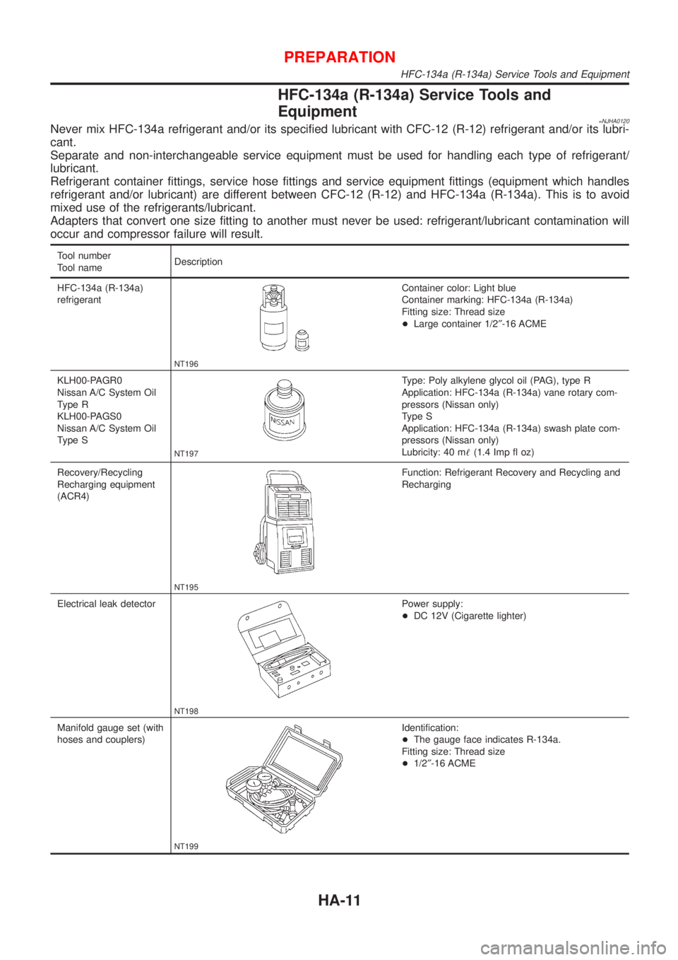
HFC-134a (R-134a) Service Tools and
Equipment
=NJHA0120Never mix HFC-134a refrigerant and/or its specified lubricant with CFC-12 (R-12) refrigerant and/or its lubri-
cant.
Separate and non-interchangeable service equipment must be used for handling each type of refrigerant/
lubricant.
Refrigerant container fittings, service hose fittings and service equipment fittings (equipment which handles
refrigerant and/or lubricant) are different between CFC-12 (R-12) and HFC-134a (R-134a). This is to avoid
mixed use of the refrigerants/lubricant.
Adapters that convert one size fitting to another must never be used: refrigerant/lubricant contamination will
occur and compressor failure will result.
Tool number
Tool nameDescription
HFC-134a (R-134a)
refrigerant
NT196
Container color: Light blue
Container marking: HFC-134a (R-134a)
Fitting size: Thread size
+Large container 1/2²-16 ACME
KLH00-PAGR0
Nissan A/C System Oil
Type R
KLH00-PAGS0
Nissan A/C System Oil
Type S
NT197
Type: Poly alkylene glycol oil (PAG), type R
Application: HFC-134a (R-134a) vane rotary com-
pressors (Nissan only)
Type S
Application: HFC-134a (R-134a) swash plate com-
pressors (Nissan only)
Lubricity: 40 m!(1.4 Imp fl oz)
Recovery/Recycling
Recharging equipment
(ACR4)
NT195
Function: Refrigerant Recovery and Recycling and
Recharging
Electrical leak detector
NT198
Power supply:
+DC 12V (Cigarette lighter)
Manifold gauge set (with
hoses and couplers)
NT199
Identification:
+The gauge face indicates R-134a.
Fitting size: Thread size
+1/2²-16 ACME
PREPARATION
HFC-134a (R-134a) Service Tools and Equipment
HA-11
Page 2056 of 2493
HFC-134a (R-134a) Service ProcedureNJHA0159SETTING OF SERVICE TOOLS AND EQUIPMENTNJHA0159S01Discharging RefrigerantNJHA0159S0101WARNING:
Avoid breathing A/C refrigerant and lubricant vapor or mist. Exposure may irritate eyes, nose and
throat. Remove HFC-134a (R-134a) from A/C system using certified service equipment meeting require-
ments of HFC-134a (R-134a) recycling equipment or HFC-134a (R-134a) recovery equipment. If acci-
dental system discharge occurs, ventilate work area before resuming service. Additional health and
safety information may be obtained from refrigerant and lubricant manufacturers.
SHA539DE
Evacuating System and Charging RefrigerantNJHA0159S0102
SHA540DC
SERVICE PROCEDURE
HFC-134a (R-134a) Service Procedure
HA-84
Page 2060 of 2493

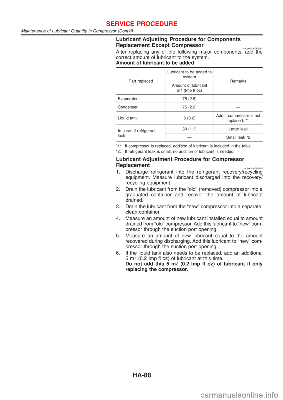
Lubricant Adjusting Procedure for Components
Replacement Except Compressor
=NJHA0160S0201After replacing any of the following major components, add the
correct amount of lubricant to the system.
Amount of lubricant to be added
Part replacedLubricant to be added to
system
Remarks
Amount of lubricant
m!(Imp fl oz)
Evaporator 75 (2.6) Ð
Condenser 75 (2.6) Ð
Liquid tank 5 (0.2)Add if compressor is not
replaced. *1
In case of refrigerant
leak30 (1.1) Large leak
Ð Small leak *2
*1: If compressor is replaced, addition of lubricant is included in the table.
*2: If refrigerant leak is small, no addition of lubricant is needed.
Lubricant Adjustment Procedure for Compressor
Replacement
NJHA0160S02021. Discharge refrigerant into the refrigerant recovery/recycling
equipment. Measure lubricant discharged into the recovery/
recycling equipment.
2. Drain the lubricant from the ªoldº (removed) compressor into a
graduated container and recover the amount of lubricant
drained.
3. Drain the lubricant from the ªnewº compressor into a separate,
clean container.
4. Measure an amount of new lubricant installed equal to amount
drained from ªoldº compressor. Add this lubricant to ªnewº com-
pressor through the suction port opening.
5. Measure an amount of new lubricant equal to the amount
recovered during discharging. Add this lubricant to ªnewº com-
pressor through the suction port opening.
6. If the liquid tank also needs to be replaced, add an additional
5m!(0.2 Imp fl oz) of lubricant at this time.
Do not add this 5 m!(0.2 Imp fl oz) of lubricant if only
replacing the compressor.
SERVICE PROCEDURE
Maintenance of Lubricant Quantity in Compressor (Cont'd)
HA-88
Page 2075 of 2493
CompressorNJHA0174
ModelCALSONIC make CSV613
TypeSwash plate (Variable displacement)
Displacement cm
3(cu in)/rev.6.0 - 125 (0.37 - 7.63)
Direction of rotationClockwise (viewed from drive end)
Drive beltQG engine model: Poly V
YD engine model: Type A
LubricantNJHA0175
ModelCALSONIC make CSV613
NameNissan A/C System Oil Type S
Part numberKLH00-PAGS0
Capacity
m!(Imp fl oz)Total in system 180 (6.3) - 200 (7.0)
Compressor (Service part) charging amount 180 (6.3) - 200 (7.0)
RefrigerantNJHA0176
TypeHFC-134a (R-134a)
Capacity kg (lb)0.45 - 0.55 (0.99 - 1.21)
Engine Idling Speed (When A/C is On)NJHA0177+Refer to EC-489 (QG), EC-702 (YD), ªIdle Speed and Ignition Timingº.
Belt TensionNJHA0178+Refer to EM-15 (QG), EM-84 (YD), ªChecking Drive Beltsº.
SERVICE DATA AND SPECIFICATIONS (SDS)
Compressor
HA-103
Page 2077 of 2493

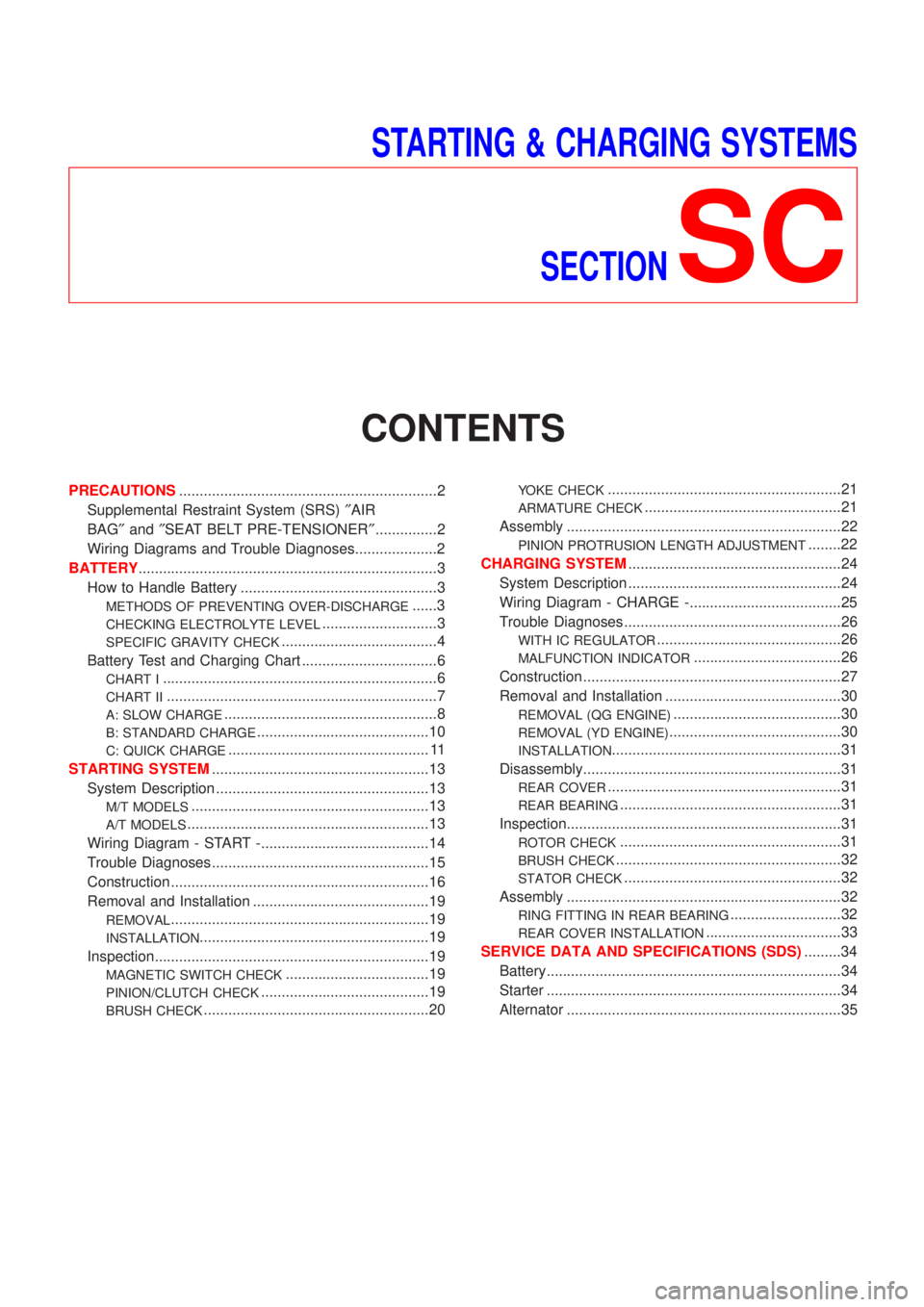
STARTING & CHARGING SYSTEMS
SECTION
SC
CONTENTS
PRECAUTIONS...............................................................2
Supplemental Restraint System (SRS)²AIR
BAG²and²SEAT BELT PRE-TENSIONER²...............2
Wiring Diagrams and Trouble Diagnoses....................2
BATTERY.........................................................................3
How to Handle Battery ................................................3
METHODS OF PREVENTING OVER-DISCHARGE......3
CHECKING ELECTROLYTE LEVEL............................3
SPECIFIC GRAVITY CHECK......................................4
Battery Test and Charging Chart .................................6
CHART I...................................................................6
CHART II..................................................................7
A: SLOW CHARGE....................................................8
B: STANDARD CHARGE..........................................10
C: QUICK CHARGE................................................. 11
STARTING SYSTEM.....................................................13
System Description ....................................................13
M/T MODELS..........................................................13
A/T MODELS...........................................................13
Wiring Diagram - START -.........................................14
Trouble Diagnoses.....................................................15
Construction ...............................................................16
Removal and Installation ...........................................19
REMOVAL...............................................................19
INSTALLATION........................................................19
Inspection...................................................................19
MAGNETIC SWITCH CHECK...................................19
PINION/CLUTCH CHECK.........................................19
BRUSH CHECK.......................................................20
YOKE CHECK.........................................................21
ARMATURE CHECK................................................21
Assembly ...................................................................22
PINION PROTRUSION LENGTH ADJUSTMENT........22
CHARGING SYSTEM....................................................24
System Description ....................................................24
Wiring Diagram - CHARGE -.....................................25
Trouble Diagnoses.....................................................26
WITH IC REGULATOR.............................................26
MALFUNCTION INDICATOR....................................26
Construction ...............................................................27
Removal and Installation ...........................................30
REMOVAL (QG ENGINE).........................................30
REMOVAL (YD ENGINE)..........................................30
INSTALLATION........................................................31
Disassembly...............................................................31
REAR COVER.........................................................31
REAR BEARING......................................................31
Inspection...................................................................31
ROTOR CHECK......................................................31
BRUSH CHECK.......................................................32
STATOR CHECK.....................................................32
Assembly ...................................................................32
RING FITTING IN REAR BEARING...........................32
REAR COVER INSTALLATION.................................33
SERVICE DATA AND SPECIFICATIONS (SDS).........34
Battery........................................................................34
Starter ........................................................................34
Alternator ...................................................................35
Page 2080 of 2493

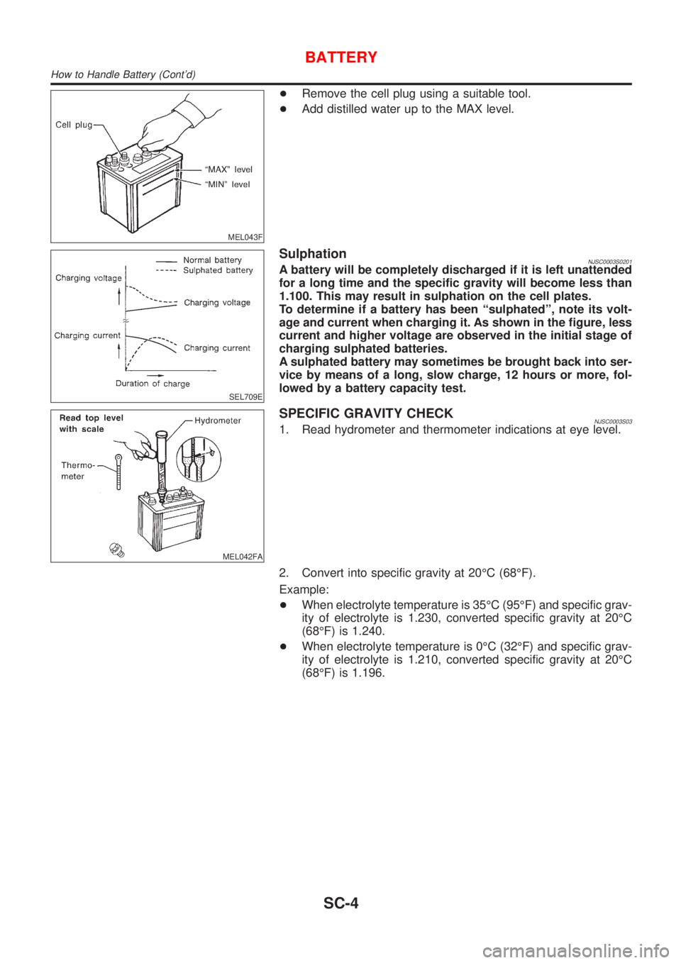
MEL043F
+Remove the cell plug using a suitable tool.
+Add distilled water up to the MAX level.
SEL709E
SulphationNJSC0003S0201A battery will be completely discharged if it is left unattended
for a long time and the specific gravity will become less than
1.100. This may result in sulphation on the cell plates.
To determine if a battery has been ªsulphatedº, note its volt-
age and current when charging it. As shown in the figure, less
current and higher voltage are observed in the initial stage of
charging sulphated batteries.
A sulphated battery may sometimes be brought back into ser-
vice by means of a long, slow charge, 12 hours or more, fol-
lowed by a battery capacity test.
MEL042FA
SPECIFIC GRAVITY CHECKNJSC0003S031. Read hydrometer and thermometer indications at eye level.
2. Convert into specific gravity at 20ÉC (68ÉF).
Example:
+When electrolyte temperature is 35ÉC (95ÉF) and specific grav-
ity of electrolyte is 1.230, converted specific gravity at 20ÉC
(68ÉF) is 1.240.
+When electrolyte temperature is 0ÉC (32ÉF) and specific grav-
ity of electrolyte is 1.210, converted specific gravity at 20ÉC
(68ÉF) is 1.196.
BATTERY
How to Handle Battery (Cont'd)
SC-4
Page 2082 of 2493
Battery Test and Charging ChartNJSC0017CHART INJSC0017S01
SEL754W
*1: SC-4
*2: SC-7*3: SC-8
*4: SC-10*5: SC-11
BATTERY
Battery Test and Charging Chart
SC-6
Page 2083 of 2493
CHART IINJSC0017S02
SEL755W
*: SC-6
+Check battery type and determine the specified current using the following table.
Fig. 1 DISCHARGING CURRENT (Load Tester)
Type Current (A)
28B19R(L) 90
34B19R(L) 99
46B24R(L) 135
55B24R(L) 135
50D23R(L) 150
55D23R(L) 180
65D26R(L) 195
80D26R(L) 195
75D31R(L) 210
063 [YUASA type code] 210
95D31R(L) 240
115D31R(L) 240
025 [YUASA type code] 240
065 [YUASA type code] 255
BATTERY
Battery Test and Charging Chart (Cont'd)
SC-7