2001 NISSAN ALMERA N16 tire type
[x] Cancel search: tire typePage 1660 of 2493
Support BearingNJAX0018S05Make sure wheel bearing rolls freely and is free from noise, cracks,
pitting or wear.
Support Bearing BracketNJAX0018S06Check support bearing bracket for cracks with a magnetic explora-
tion or dyeing test.
ASSEMBLYNJAX0019+After drive shaft has been assembled, ensure that it
moves smoothly over its entire range without binding.
+Use NISSAN GENUINE GREASE or equivalent after every
overhaul.
SFA800
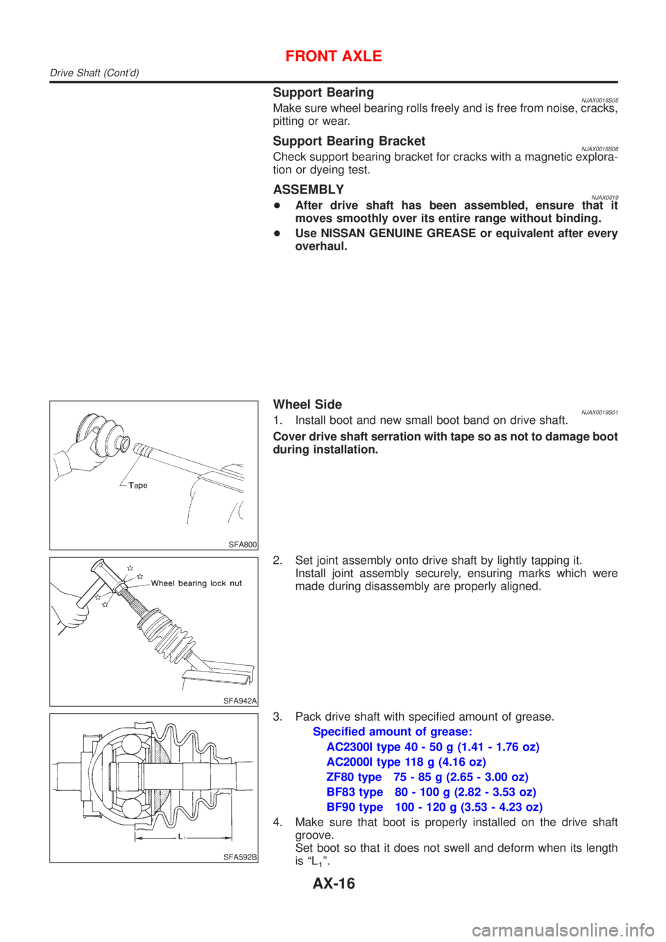
Wheel SideNJAX0019S011. Install boot and new small boot band on drive shaft.
Cover drive shaft serration with tape so as not to damage boot
during installation.
SFA942A
2. Set joint assembly onto drive shaft by lightly tapping it.
Install joint assembly securely, ensuring marks which were
made during disassembly are properly aligned.
SFA592B
3. Pack drive shaft with specified amount of grease.
Specified amount of grease:
AC2300I type 40 - 50 g (1.41 - 1.76 oz)
AC2000I type 118 g (4.16 oz)
ZF80 type 75 - 85 g (2.65 - 3.00 oz)
BF83 type 80 - 100 g (2.82 - 3.53 oz)
BF90 type 100 - 120 g (3.53 - 4.23 oz)
4. Make sure that boot is properly installed on the drive shaft
groove.
Set boot so that it does not swell and deform when its length
is ªL
1º.
FRONT AXLE
Drive Shaft (Cont'd)
AX-16
Page 1679 of 2493
SFA975B
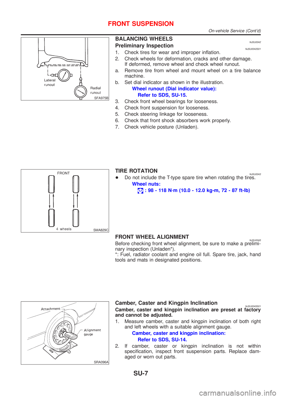
BALANCING WHEELSNJSU0042Preliminary InspectionNJSU0042S011. Check tires for wear and improper inflation.
2. Check wheels for deformation, cracks and other damage.
If deformed, remove wheel and check wheel runout.
a. Remove tire from wheel and mount wheel on a tire balance
machine.
b. Set dial indicator as shown in the illustration.
Wheel runout (Dial indicator value):
Refer to SDS, SU-15.
3. Check front wheel bearings for looseness.
4. Check front suspension for looseness.
5. Check steering linkage for looseness.
6. Check that front shock absorbers work properly.
7. Check vehicle posture (Unladen).
SMA829C
TIRE ROTATIONNJSU0043+Do not include the T-type spare tire when rotating the tires.
Wheel nuts:
: 98 - 118 N´m (10.0 - 12.0 kg-m, 72 - 87 ft-lb)
FRONT WHEEL ALIGNMENTNJSU0045Before checking front wheel alignment, be sure to make a prelimi-
nary inspection (Unladen*).
*: Fuel, radiator coolant and engine oil full. Spare tire, jack, hand
tools and mats in designated positions.
SRA096A
Camber, Caster and Kingpin InclinationNJSU0045S01Camber, caster and kingpin inclination are preset at factory
and cannot be adjusted.
1. Measure camber, caster and kingpin inclination of both right
and left wheels with a suitable alignment gauge.
Camber, caster and kingpin inclination:
Refer to SDS, SU-14.
2. If camber, caster or kingpin inclination is not within
specification, inspect front suspension parts. Replace dam-
aged or worn out parts.
FRONT SUSPENSION
On-vehicle Service (Cont'd)
SU-7
Page 1686 of 2493
Service Data and Specifications (SDS)
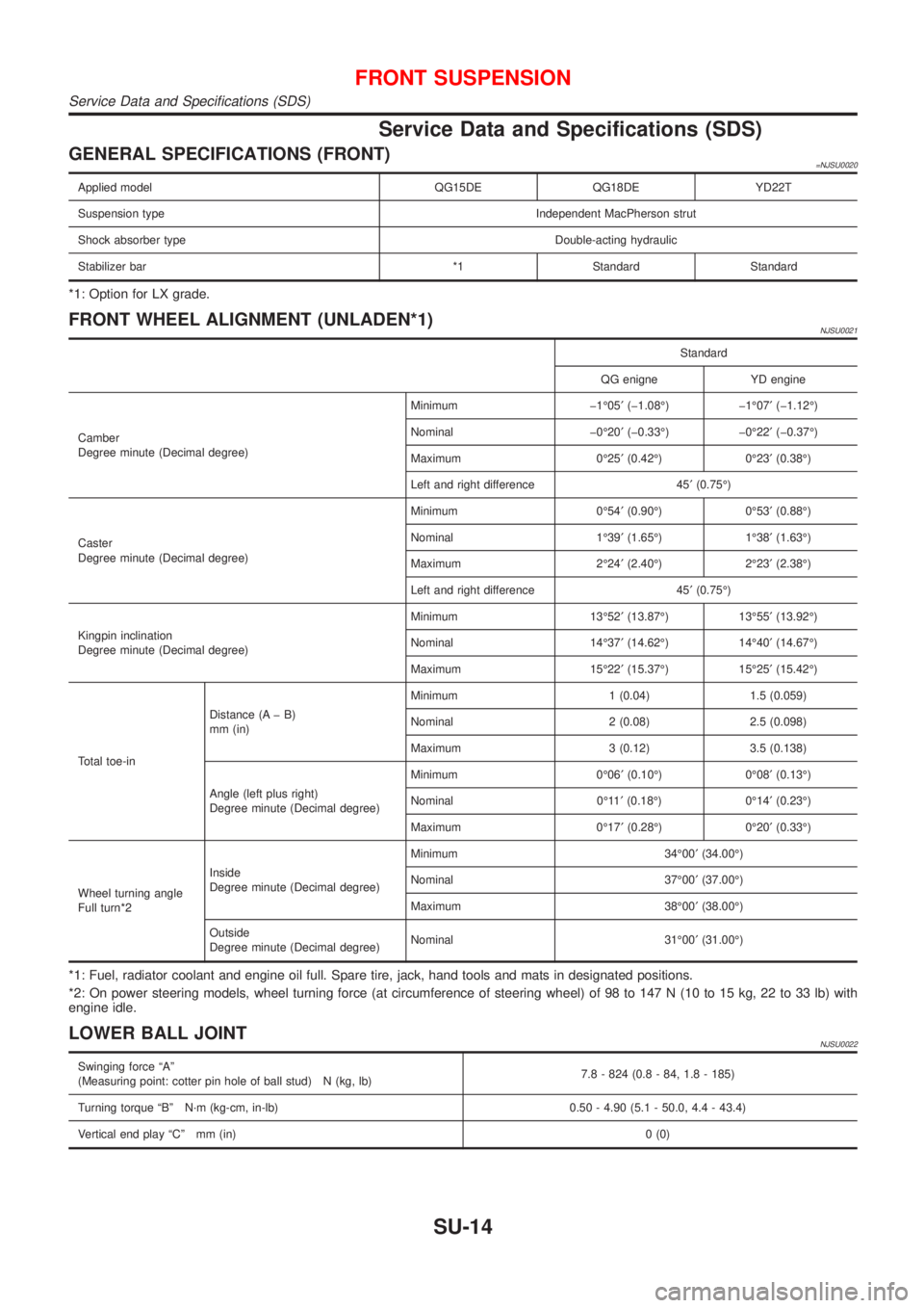
GENERAL SPECIFICATIONS (FRONT)=NJSU0020
Applied model QG15DE QG18DE YD22T
Suspension type Independent MacPherson strut
Shock absorber type Double-acting hydraulic
Stabilizer bar *1 Standard Standard
*1: Option for LX grade.
FRONT WHEEL ALIGNMENT (UNLADEN*1)NJSU0021
Standard
QG enigne YD engine
Camber
Degree minute (Decimal degree)Minimum þ1É05¢(þ1.08É) þ1É07¢(þ1.12É)
Nominal þ0É20¢(þ0.33É) þ0É22¢(þ0.37É)
Maximum 0É25¢(0.42É) 0É23¢(0.38É)
Left and right difference 45¢(0.75É)
Caster
Degree minute (Decimal degree)Minimum 0É54¢(0.90É) 0É53¢(0.88É)
Nominal 1É39¢(1.65É) 1É38¢(1.63É)
Maximum 2É24¢(2.40É) 2É23¢(2.38É)
Left and right difference 45¢(0.75É)
Kingpin inclination
Degree minute (Decimal degree)Minimum 13É52¢(13.87É) 13É55¢(13.92É)
Nominal 14É37¢(14.62É) 14É40¢(14.67É)
Maximum 15É22¢(15.37É) 15É25¢(15.42É)
Total toe-inDistance (A þ B)
mm (in)Minimum 1 (0.04) 1.5 (0.059)
Nominal 2 (0.08) 2.5 (0.098)
Maximum 3 (0.12) 3.5 (0.138)
Angle (left plus right)
Degree minute (Decimal degree)Minimum 0É06¢(0.10É) 0É08¢(0.13É)
Nominal 0É11¢(0.18É) 0É14¢(0.23É)
Maximum 0É17¢(0.28É) 0É20¢(0.33É)
Wheel turning angle
Full turn*2Inside
Degree minute (Decimal degree)Minimum 34É00¢(34.00É)
Nominal 37É00¢(37.00É)
Maximum 38É00¢(38.00É)
Outside
Degree minute (Decimal degree)Nominal 31É00¢(31.00É)
*1: Fuel, radiator coolant and engine oil full. Spare tire, jack, hand tools and mats in designated positions.
*2: On power steering models, wheel turning force (at circumference of steering wheel) of 98 to 147 N (10 to 15 kg, 22 to 33 lb) with
engine idle.
LOWER BALL JOINTNJSU0022
Swinging force ªAº
(Measuring point: cotter pin hole of ball stud) N (kg, lb)7.8 - 824 (0.8 - 84, 1.8 - 185)
Turning torque ªBº N´m (kg-cm, in-lb) 0.50 - 4.90 (5.1 - 50.0, 4.4 - 43.4)
Vertical end play ªCº mm (in)0 (0)
FRONT SUSPENSION
Service Data and Specifications (SDS)
SU-14
Page 1687 of 2493
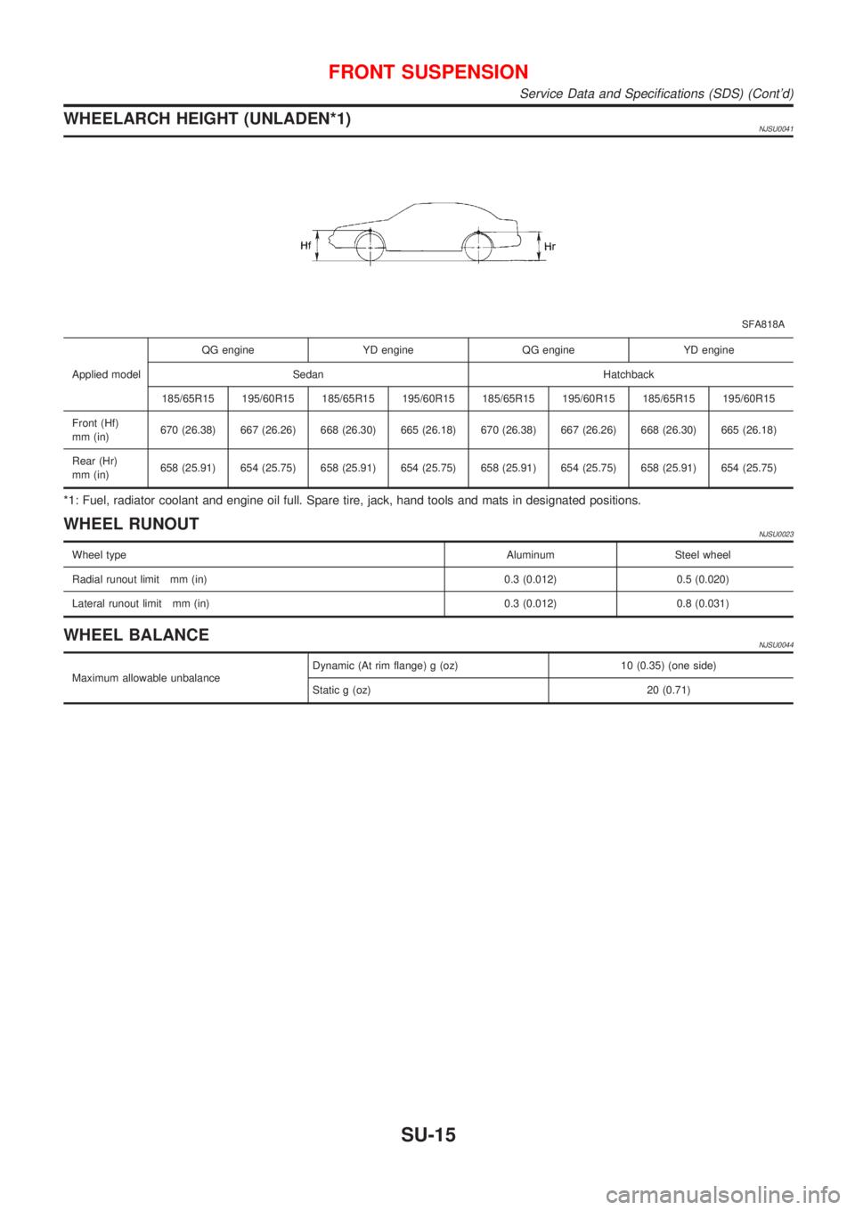
WHEELARCH HEIGHT (UNLADEN*1)NJSU0041
SFA818A
Applied modelQG engine YD engine QG engine YD engine
Sedan Hatchback
185/65R15 195/60R15 185/65R15 195/60R15 185/65R15 195/60R15 185/65R15 195/60R15
Front (Hf)
mm (in)670 (26.38) 667 (26.26) 668 (26.30) 665 (26.18) 670 (26.38) 667 (26.26) 668 (26.30) 665 (26.18)
Rear (Hr)
mm (in)658 (25.91) 654 (25.75) 658 (25.91) 654 (25.75) 658 (25.91) 654 (25.75) 658 (25.91) 654 (25.75)
*1: Fuel, radiator coolant and engine oil full. Spare tire, jack, hand tools and mats in designated positions.
WHEEL RUNOUTNJSU0023
Wheel typeAluminum Steel wheel
Radial runout limit mm (in) 0.3 (0.012) 0.5 (0.020)
Lateral runout limit mm (in) 0.3 (0.012) 0.8 (0.031)
WHEEL BALANCENJSU0044
Maximum allowable unbalanceDynamic (At rim flange) g (oz) 10 (0.35) (one side)
Static g (oz) 20 (0.71)
FRONT SUSPENSION
Service Data and Specifications (SDS) (Cont'd)
SU-15
Page 1697 of 2493
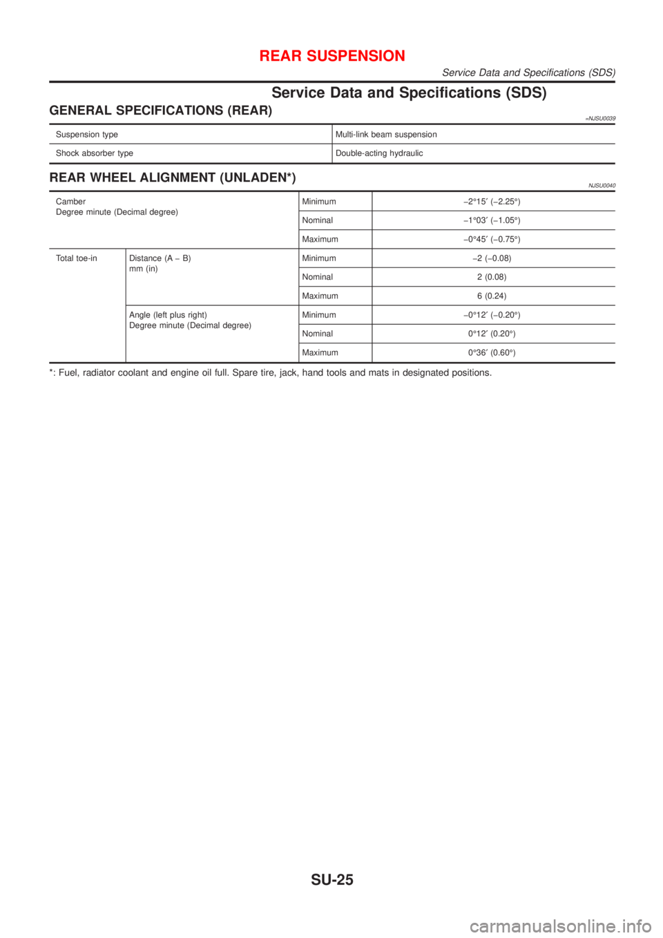
Service Data and Specifications (SDS)
GENERAL SPECIFICATIONS (REAR)=NJSU0039
Suspension type Multi-link beam suspension
Shock absorber type Double-acting hydraulic
REAR WHEEL ALIGNMENT (UNLADEN*)NJSU0040
Camber
Degree minute (Decimal degree)Minimum þ2É15¢(þ2.25É)
Nominal þ1É03¢(þ1.05É)
Maximum þ0É45¢(þ0.75É)
Total toe-in Distance (A þ B)
mm (in)Minimum þ2 (þ0.08)
Nominal 2 (0.08)
Maximum 6 (0.24)
Angle (left plus right)
Degree minute (Decimal degree)Minimum þ0É12¢(þ0.20É)
Nominal 0É12¢(0.20É)
Maximum 0É36¢(0.60É)
*: Fuel, radiator coolant and engine oil full. Spare tire, jack, hand tools and mats in designated positions.
REAR SUSPENSION
Service Data and Specifications (SDS)
SU-25
Page 2154 of 2493
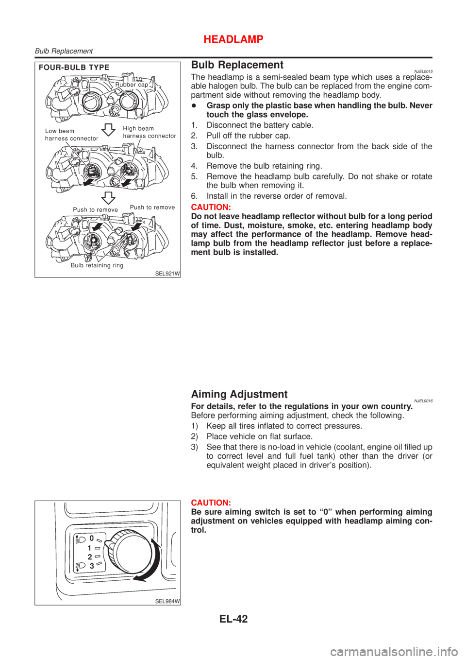
SEL921W
Bulb ReplacementNJEL0015The headlamp is a semi-sealed beam type which uses a replace-
able halogen bulb. The bulb can be replaced from the engine com-
partment side without removing the headlamp body.
+Grasp only the plastic base when handling the bulb. Never
touch the glass envelope.
1. Disconnect the battery cable.
2. Pull off the rubber cap.
3. Disconnect the harness connector from the back side of the
bulb.
4. Remove the bulb retaining ring.
5. Remove the headlamp bulb carefully. Do not shake or rotate
the bulb when removing it.
6. Install in the reverse order of removal.
CAUTION:
Do not leave headlamp reflector without bulb for a long period
of time. Dust, moisture, smoke, etc. entering headlamp body
may affect the performance of the headlamp. Remove head-
lamp bulb from the headlamp reflector just before a replace-
ment bulb is installed.
Aiming AdjustmentNJEL0016For details, refer to the regulations in your own country.
Before performing aiming adjustment, check the following.
1) Keep all tires inflated to correct pressures.
2) Place vehicle on flat surface.
3) See that there is no-load in vehicle (coolant, engine oil filled up
to correct level and full fuel tank) other than the driver (or
equivalent weight placed in driver's position).
SEL984W
CAUTION:
Be sure aiming switch is set to ª0º when performing aiming
adjustment on vehicles equipped with headlamp aiming con-
trol.
HEADLAMP
Bulb Replacement
EL-42
Page 2373 of 2493
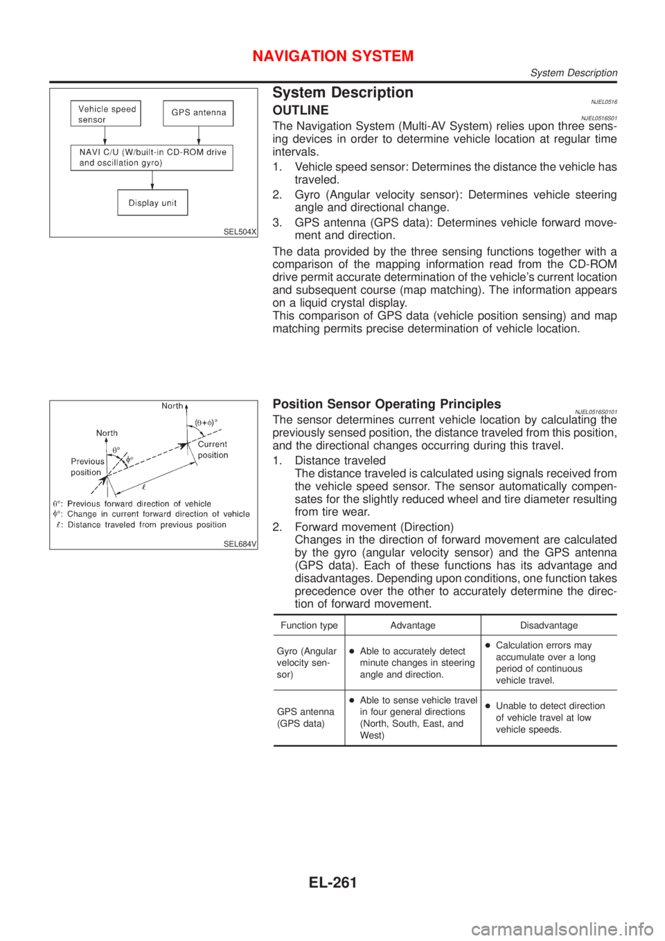
SEL504X
System DescriptionNJEL0516OUTLINENJEL0516S01The Navigation System (Multi-AV System) relies upon three sens-
ing devices in order to determine vehicle location at regular time
intervals.
1. Vehicle speed sensor: Determines the distance the vehicle has
traveled.
2. Gyro (Angular velocity sensor): Determines vehicle steering
angle and directional change.
3. GPS antenna (GPS data): Determines vehicle forward move-
ment and direction.
The data provided by the three sensing functions together with a
comparison of the mapping information read from the CD-ROM
drive permit accurate determination of the vehicle's current location
and subsequent course (map matching). The information appears
on a liquid crystal display.
This comparison of GPS data (vehicle position sensing) and map
matching permits precise determination of vehicle location.
SEL684V
Position Sensor Operating PrinciplesNJEL0516S0101The sensor determines current vehicle location by calculating the
previously sensed position, the distance traveled from this position,
and the directional changes occurring during this travel.
1. Distance traveled
The distance traveled is calculated using signals received from
the vehicle speed sensor. The sensor automatically compen-
sates for the slightly reduced wheel and tire diameter resulting
from tire wear.
2. Forward movement (Direction)
Changes in the direction of forward movement are calculated
by the gyro (angular velocity sensor) and the GPS antenna
(GPS data). Each of these functions has its advantage and
disadvantages. Depending upon conditions, one function takes
precedence over the other to accurately determine the direc-
tion of forward movement.
Function type Advantage Disadvantage
Gyro (Angular
velocity sen-
sor)+Able to accurately detect
minute changes in steering
angle and direction.+Calculation errors may
accumulate over a long
period of continuous
vehicle travel.
GPS antenna
(GPS data)+Able to sense vehicle travel
in four general directions
(North, South, East, and
West)+Unable to detect direction
of vehicle travel at low
vehicle speeds.
NAVIGATION SYSTEM
System Description
EL-261