2001 NISSAN ALMERA N16 checking oil
[x] Cancel search: checking oilPage 3 of 2493

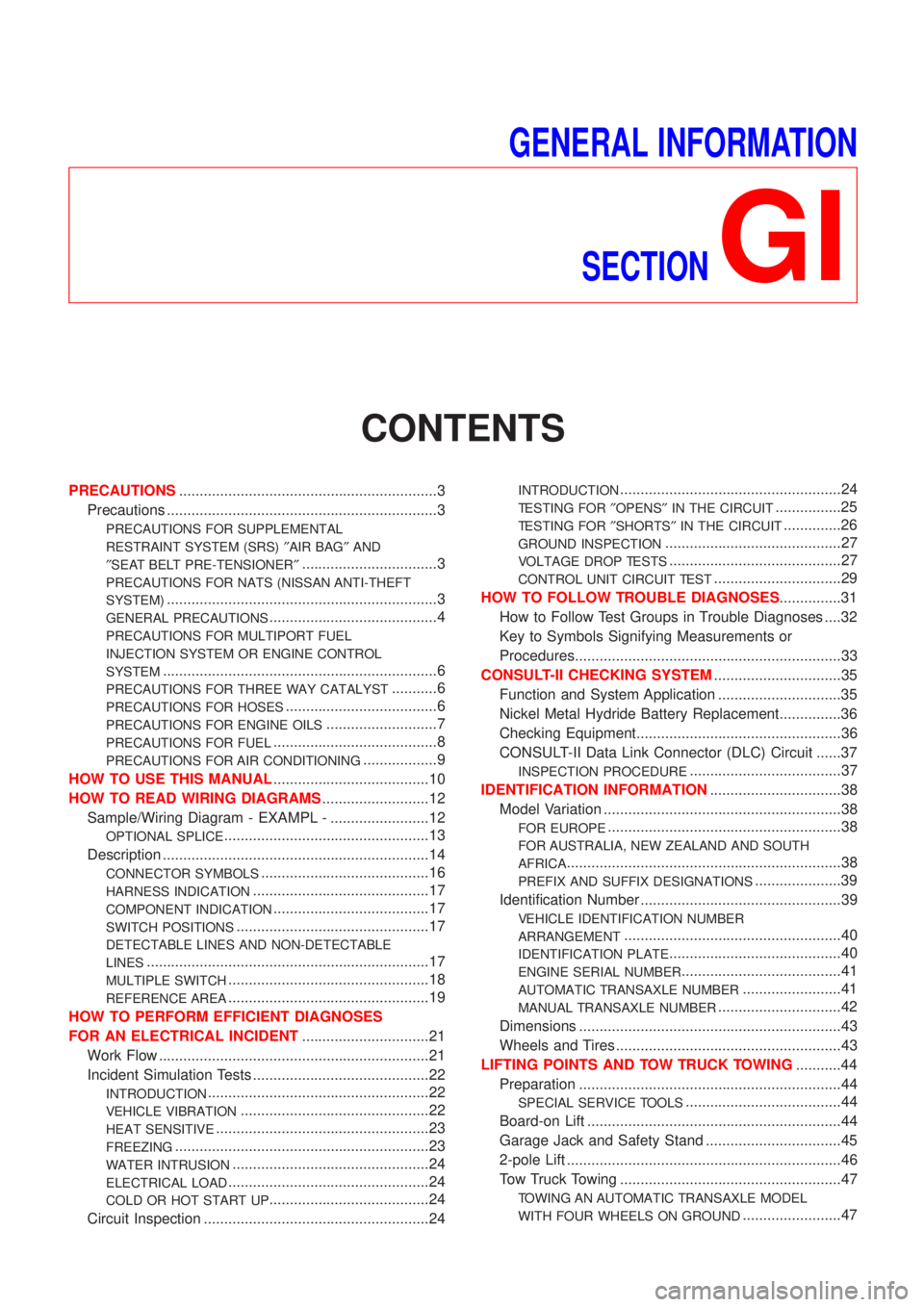
GENERAL INFORMATION
SECTION
GI
CONTENTS
PRECAUTIONS...............................................................3
Precautions ..................................................................3
PRECAUTIONS FOR SUPPLEMENTAL
RESTRAINT SYSTEM (SRS)²AIR BAG²AND
²SEAT BELT PRE-TENSIONER²
.................................3
PRECAUTIONS FOR NATS (NISSAN ANTI-THEFT
SYSTEM)
..................................................................3
GENERAL PRECAUTIONS.........................................4
PRECAUTIONS FOR MULTIPORT FUEL
INJECTION SYSTEM OR ENGINE CONTROL
SYSTEM
...................................................................6
PRECAUTIONS FOR THREE WAY CATALYST...........6
PRECAUTIONS FOR HOSES.....................................6
PRECAUTIONS FOR ENGINE OILS...........................7
PRECAUTIONS FOR FUEL........................................8
PRECAUTIONS FOR AIR CONDITIONING..................9
HOW TO USE THIS MANUAL......................................10
HOW TO READ WIRING DIAGRAMS..........................12
Sample/Wiring Diagram - EXAMPL - ........................12
OPTIONAL SPLICE..................................................13
Description .................................................................14
CONNECTOR SYMBOLS.........................................16
HARNESS INDICATION...........................................17
COMPONENT INDICATION......................................17
SWITCH POSITIONS...............................................17
DETECTABLE LINES AND NON-DETECTABLE
LINES
.....................................................................17
MULTIPLE SWITCH.................................................18
REFERENCE AREA.................................................19
HOW TO PERFORM EFFICIENT DIAGNOSES
FOR AN ELECTRICAL INCIDENT...............................21
Work Flow ..................................................................21
Incident Simulation Tests ...........................................22
INTRODUCTION......................................................22
VEHICLE VIBRATION..............................................22
HEAT SENSITIVE....................................................23
FREEZING..............................................................23
WATER INTRUSION................................................24
ELECTRICAL LOAD.................................................24
COLD OR HOT START UP.......................................24
Circuit Inspection .......................................................24
INTRODUCTION......................................................24
TESTING FOR²OPENS²IN THE CIRCUIT................25
TESTING FOR²SHORTS²IN THE CIRCUIT..............26
GROUND INSPECTION...........................................27
VOLTAGE DROP TESTS..........................................27
CONTROL UNIT CIRCUIT TEST...............................29
HOW TO FOLLOW TROUBLE DIAGNOSES...............31
How to Follow Test Groups in Trouble Diagnoses ....32
Key to Symbols Signifying Measurements or
Procedures.................................................................33
CONSULT-II CHECKING SYSTEM...............................35
Function and System Application ..............................35
Nickel Metal Hydride Battery Replacement...............36
Checking Equipment..................................................36
CONSULT-II Data Link Connector (DLC) Circuit ......37
INSPECTION PROCEDURE.....................................37
IDENTIFICATION INFORMATION................................38
Model Variation ..........................................................38
FOR EUROPE.........................................................38
FOR AUSTRALIA, NEW ZEALAND AND SOUTH
AFRICA
...................................................................38
PREFIX AND SUFFIX DESIGNATIONS.....................39
Identification Number .................................................39
VEHICLE IDENTIFICATION NUMBER
ARRANGEMENT
.....................................................40
IDENTIFICATION PLATE..........................................40
ENGINE SERIAL NUMBER.......................................41
AUTOMATIC TRANSAXLE NUMBER........................41
MANUAL TRANSAXLE NUMBER..............................42
Dimensions ................................................................43
Wheels and Tires .......................................................43
LIFTING POINTS AND TOW TRUCK TOWING...........44
Preparation ................................................................44
SPECIAL SERVICE TOOLS......................................44
Board-on Lift ..............................................................44
Garage Jack and Safety Stand .................................45
2-pole Lift ...................................................................46
Tow Truck Towing ......................................................47
TOWING AN AUTOMATIC TRANSAXLE MODEL
WITH FOUR WHEELS ON GROUND
........................47
Page 13 of 2493

+SERVICE DATA AND SPECIFICATIONSare contained at the end of each section for quick reference of
data.
+The followingSYMBOLS AND ABBREVIATIONSare used:
SYMBOL ABBREVIATION SYMBOL ABBREVIATION
Tightening torque
2WD2-Wheel Drive
Should be lubricated with grease. Unless oth-
erwise indicated, use recommended multi-pur-
pose grease.A/CAir Conditioner
Should be lubricated with oil. P/S Power Steering
Sealing point SST Special Service Tools
Checking point SAE Society of Automotive Engineers, Inc.
Always replace after every disassembly. ATF Automatic Transmission Fluid
jP
Apply petroleum jelly.
D1Drive range 1st gear
Apply ATF. D2Drive range 2nd gear
HSelect with proper thickness. D
3Drive range 3rd gear
IAdjustment is required. D
4Drive range 4th gear
SDS Service Data and Specifications OD Overdrive
LH, RH Left-Hand, Right-Hand 2
22nd range 2nd gear
FR, RR Front, Rear 2
12nd range 1st gear
M/T Manual Transaxle/Transmission 1
21st range 2nd gear
A/T Automatic Transaxle/Transmission 1
11st range 1st gear
HOW TO USE THIS MANUAL
GI-11
Page 66 of 2493

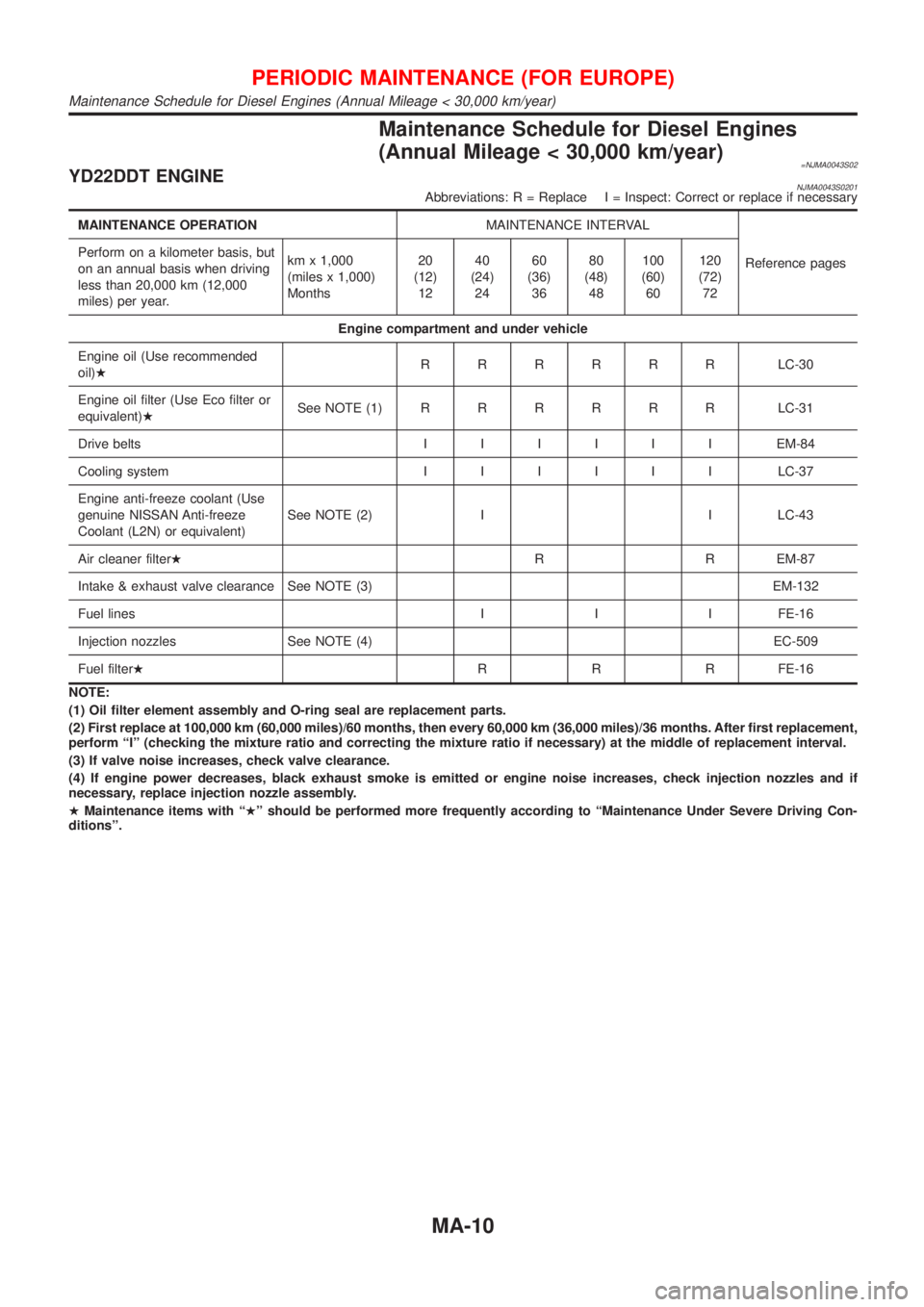
Maintenance Schedule for Diesel Engines
(Annual Mileage < 30,000 km/year)
=NJMA0043S02YD22DDT ENGINENJMA0043S0201Abbreviations: R = Replace I = Inspect: Correct or replace if necessary
MAINTENANCE OPERATIONMAINTENANCE INTERVAL
Reference pages Perform on a kilometer basis, but
on an annual basis when driving
less than 20,000 km (12,000
miles) per year.km x 1,000
(miles x 1,000)
Months20
(12)
1240
(24)
2460
(36)
3680
(48)
48100
(60)
60120
(72)
72
Engine compartment and under vehicle
Engine oil (Use recommended
oil)HRRRRRRLC-30
Engine oil filter (Use Eco filter or
equivalent)HSee NOTE (1)RRRRRRLC-31
Drive beltsIIIIIIEM-84
Cooling systemIIIIIILC-37
Engine anti-freeze coolant (Use
genuine NISSAN Anti-freeze
Coolant (L2N) or equivalent)See NOTE (2) I I LC-43
Air cleaner filterHR R EM-87
Intake & exhaust valve clearance See NOTE (3) EM-132
Fuel lines I I I FE-16
Injection nozzles See NOTE (4) EC-509
Fuel filterHR R R FE-16
NOTE:
(1) Oil filter element assembly and O-ring seal are replacement parts.
(2) First replace at 100,000 km (60,000 miles)/60 months, then every 60,000 km (36,000 miles)/36 months. After first replacement,
perform ªIº (checking the mixture ratio and correcting the mixture ratio if necessary) at the middle of replacement interval.
(3) If valve noise increases, check valve clearance.
(4) If engine power decreases, black exhaust smoke is emitted or engine noise increases, check injection nozzles and if
necessary, replace injection nozzle assembly.
HMaintenance items with ªHº should be performed more frequently according to ªMaintenance Under Severe Driving Con-
ditionsº.
PERIODIC MAINTENANCE (FOR EUROPE)
Maintenance Schedule for Diesel Engines (Annual Mileage < 30,000 km/year)
MA-10
Page 70 of 2493

Maintenance Schedule for Petrol Engines
(Annual Mileage > 30,000 km/year)
=NJMA0043S04QG15DE/QG18DE ENGINESNJMA0043S0401Abbreviations: R = Replace I = Inspect: Correct or replace if necessary
MAINTENANCE OPERATIONMAINTENANCE INTERVAL
Refer-
ence
pages Perform on a kilometer basis only.km x 1,000
(miles x 1,000)15
(9)30
(18)45
(27)60
(36)75
(45)90
(54)105
(63)120
(72)
Engine compartment and under vehicle
Engine oil (Use recommended oil)HRRRRRRRRLC-8
Engine oil filter (Use NISSAN genuine
part or equivalent)HRRRRRRRRLC-9
Drive beltsIIIIIIIIEM-15
Cooling systemIIIILC-12
Engine anti-freeze coolant (Use genu-
ine NISSAN Anti-Freeze Coolant (L2N)
or equivalent)See NOTE (1) I R I LC-17
Air cleaner filterHR R EM-17
Intake & exhaust valve clearance See NOTE (2) EM-42
Fuel and EVAP vapor lines I IFE-5/
EC-36
Spark plugsRRRREM-18
Fuel filter See NOTE (3) FE-9
Heated oxygen sensorHSee NOTE (4)GI-40/
EC-45
NOTE:
(1) First replace at 90,000 km (54,000 miles), then every 60,000 km (36,000 miles). Perform ªIº (checking the mixture ratio and
correcting the mixture ratio if necessary) at the middle of replacement interval.
(2) Periodic maintenance is not required. However, if valve noise increases, check valve clearance.
(3) Fuel filter is maintenance-free. For service procedures, refer to FE section.
(4) Perform only according to ªMaintenance Under Severe Driving Conditionsº for models without Euro-OBD system. For
models with Euro-OBD system, periodic maintenance is not required.
HMaintenance items with ªHº should be performed more frequently according to ªMaintenance Under Severe Driving Con-
ditionsº.
PERIODIC MAINTENANCE (FOR EUROPE)
Maintenance Schedule for Petrol Engines (Annual Mileage > 30,000 km/year)
MA-14
Page 79 of 2493

ENGINE MECHANICAL
SECTION
EM
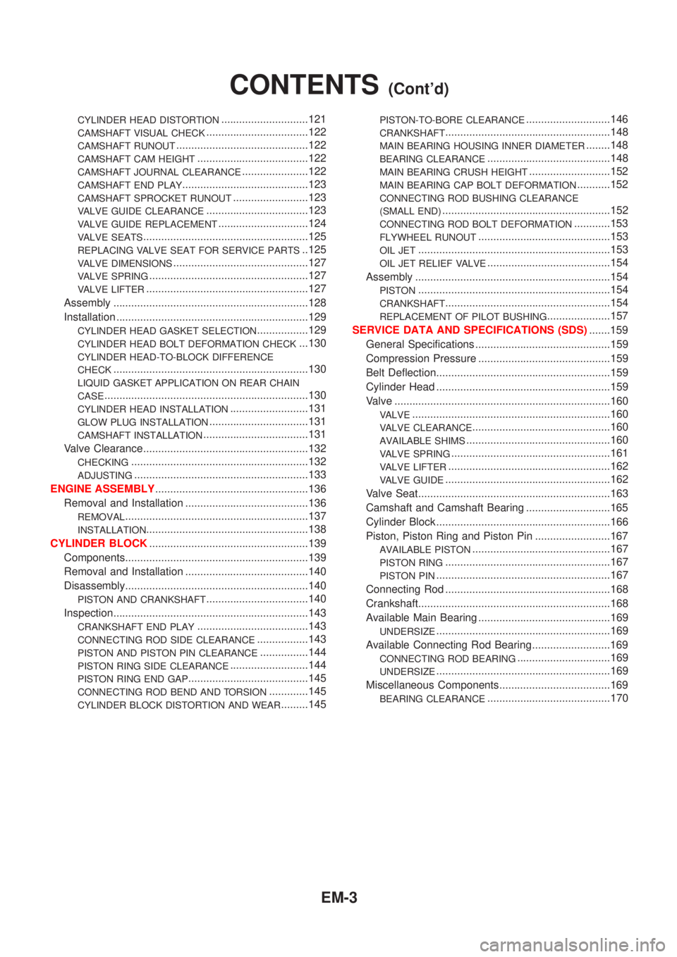
CONTENTS
QG
PRECAUTIONS...............................................................4
Parts Requiring Angular Tightening .............................4
Liquid Gasket Application Procedure ..........................4
PREPARATION...............................................................5
Special Service Tools ..................................................5
Commercial Service Tools ...........................................7
NOISE, VIBRATION AND HARSHNESS (NVH)
TROUBLESHOOTING.....................................................9
NVH Troubleshooting - Engine Noise .........................9
OUTER COMPONENT PARTS..................................... 11
Removal and Installation ........................................... 11
MEASUREMENT OF COMPRESSION PRESSURE....14
DRIVE BELTS................................................................15
Checking ....................................................................15
AIR CLEANER...............................................................17
Cleaning and Changing .............................................17
VISCOUS PAPER TYPE...........................................17
SPARK PLUG................................................................18
Checking and Changing ............................................18
OIL PAN.........................................................................19
Components...............................................................19
Removal .....................................................................19
Installation ..................................................................20
TIMING CHAIN..............................................................22
Components...............................................................22
Removal .....................................................................23
Inspection...................................................................26
Installation ..................................................................27
OIL SEAL.......................................................................31
Replacement ..............................................................31
VALVE OIL SEAL.....................................................31
FRONT OIL SEAL....................................................31
REAR OIL SEAL......................................................32
CYLINDER HEAD..........................................................33
Components...............................................................33
Removal .....................................................................34
Disassembly...............................................................36Inspection...................................................................36
CYLINDER HEAD DISTORTION...............................36
CAMSHAFT VISUAL CHECK....................................36
CAMSHAFT RUNOUT..............................................37
CAMSHAFT CAM HEIGHT.......................................37
CAMSHAFT JOURNAL CLEARANCE........................37
CAMSHAFT END PLAY............................................38
CAMSHAFT SPROCKET RUNOUT...........................38
VALVE GUIDE CLEARANCE....................................38
VALVE GUIDE REPLACEMENT................................39
VALVE SEATS.........................................................40
REPLACING VALVE SEAT FOR SERVICE PARTS....40
VALVE DIMENSIONS...............................................41
VALVE SPRING.......................................................41
VALVE LIFTER AND VALVE SHIM............................41
Valve Clearance.........................................................42
CHECKING.............................................................42
ADJUSTING............................................................43
Assembly ...................................................................45
Installation ..................................................................45
ENGINE ASSEMBLY.....................................................49
Removal and Installation ...........................................49
REMOVAL...............................................................50
INSTALLATION........................................................51
CYLINDER BLOCK.......................................................52
Components...............................................................52
Removal and Installation ...........................................53
Disassembly...............................................................53
PISTON AND CRANKSHAFT....................................53
Inspection...................................................................54
PISTON AND PISTON PIN CLEARANCE..................54
PISTON RING SIDE CLEARANCE............................54
PISTON RING END GAP..........................................54
CONNECTING ROD BEND AND TORSION...............55
CYLINDER BLOCK DISTORTION AND WEAR...........55
PISTON-TO-BORE CLEARANCE..............................56
CRANKSHAFT.........................................................57
BEARING CLEARANCE...........................................57
CONNECTING ROD BUSHING CLEARANCE
(SMALL END)
..........................................................59
Page 81 of 2493

CYLINDER HEAD DISTORTION.............................121
CAMSHAFT VISUAL CHECK..................................122
CAMSHAFT RUNOUT............................................122
CAMSHAFT CAM HEIGHT.....................................122
CAMSHAFT JOURNAL CLEARANCE......................122
CAMSHAFT END PLAY..........................................123
CAMSHAFT SPROCKET RUNOUT.........................123
VALVE GUIDE CLEARANCE..................................123
VALVE GUIDE REPLACEMENT..............................124
VALVE SEATS.......................................................125
REPLACING VALVE SEAT FOR SERVICE PARTS..125
VALVE DIMENSIONS.............................................127
VALVE SPRING.....................................................127
VALVE LIFTER......................................................127
Assembly .................................................................128
Installation ................................................................129
CYLINDER HEAD GASKET SELECTION.................129
CYLINDER HEAD BOLT DEFORMATION CHECK...130
CYLINDER HEAD-TO-BLOCK DIFFERENCE
CHECK
.................................................................130
LIQUID GASKET APPLICATION ON REAR CHAIN
CASE
....................................................................130
CYLINDER HEAD INSTALLATION..........................131
GLOW PLUG INSTALLATION.................................131
CAMSHAFT INSTALLATION...................................131
Valve Clearance.......................................................132
CHECKING...........................................................132
ADJUSTING..........................................................133
ENGINE ASSEMBLY...................................................136
Removal and Installation .........................................136
REMOVAL.............................................................137
INSTALLATION......................................................138
CYLINDER BLOCK.....................................................139
Components.............................................................139
Removal and Installation .........................................140
Disassembly.............................................................140
PISTON AND CRANKSHAFT..................................140
Inspection.................................................................143
CRANKSHAFT END PLAY.....................................143
CONNECTING ROD SIDE CLEARANCE.................143
PISTON AND PISTON PIN CLEARANCE................144
PISTON RING SIDE CLEARANCE..........................144
PISTON RING END GAP........................................145
CONNECTING ROD BEND AND TORSION.............145
CYLINDER BLOCK DISTORTION AND WEAR.........145
PISTON-TO-BORE CLEARANCE............................146
CRANKSHAFT.......................................................148
MAIN BEARING HOUSING INNER DIAMETER........148
BEARING CLEARANCE.........................................148
MAIN BEARING CRUSH HEIGHT...........................152
MAIN BEARING CAP BOLT DEFORMATION...........152
CONNECTING ROD BUSHING CLEARANCE
(SMALL END)
........................................................152
CONNECTING ROD BOLT DEFORMATION............153
FLYWHEEL RUNOUT............................................153
OIL JET................................................................153
OIL JET RELIEF VALVE.........................................154
Assembly .................................................................154
PISTON................................................................154
CRANKSHAFT.......................................................154
REPLACEMENT OF PILOT BUSHING.....................157
SERVICE DATA AND SPECIFICATIONS (SDS).......159
General Specifications .............................................159
Compression Pressure ............................................159
Belt Deflection..........................................................159
Cylinder Head ..........................................................159
Valve ........................................................................160
VALVE..................................................................160
VALVE CLEARANCE..............................................160
AVAILABLE SHIMS................................................160
VALVE SPRING.....................................................161
VALVE LIFTER......................................................162
VALVE GUIDE.......................................................162
Valve Seat................................................................163
Camshaft and Camshaft Bearing ............................165
Cylinder Block ..........................................................166
Piston, Piston Ring and Piston Pin .........................167
AVAILABLE PISTON..............................................167
PISTON RING.......................................................167
PISTON PIN..........................................................167
Connecting Rod .......................................................168
Crankshaft................................................................168
Available Main Bearing ............................................169
UNDERSIZE..........................................................169
Available Connecting Rod Bearing..........................169
CONNECTING ROD BEARING...............................169
UNDERSIZE..........................................................169
Miscellaneous Components.....................................169
BEARING CLEARANCE.........................................170
CONTENTS(Cont'd)
EM-3
Page 92 of 2493

NJEM0007
1. Warm up engine.
2. Turn ignition switch OFF.
3. Release fuel pressure.
Refer to EC-38, ªReleasing Fuel Pressureº.
4. Remove ignition coils.
5. Remove spark plugs.
+Clean area around plug with compressed air before removing
the spark plug.
SEM973E
AEM308
6. Attach a compression tester to No. 1 cylinder.
7. Depress accelerator pedal fully to keep throttle valve wide
open.
8. Crank engine and record highest gauge indication.
9. Repeat the measurement on each cylinder as shown above.
+Always use a fully-charged battery to obtain specified
engine speed.
Compression pressure: kPa (bar, kg/cm
2, psi)/rpm
QG18DE
Standard
1,324 (13.24, 13.5, 192)/350
Minimum
1,128 (11.28, 11.5, 164)/350
Maximum allowable difference between cylinders
98 (0.98, 1.0, 14)/350
QG15DE
Standard
1,372 (13.720, 13.99, 198.9)/350
Minimum
1,176 (11.759, 11.99, 170.5)/350
Maximum allowable difference between cylinders
98 (0.98, 1.0, 14)/350
10. If cylinder compression in one or more cylinders is low, pour a
small amount of engine oil into the cylinder through the spark
plug hole and retest compression.
+If adding oil improves cylinder compression, piston rings
may be worn or damaged. If so, replace piston rings after
checking piston.
+If pressure stays low, a valve may be sticking or seating
improperly. Inspect and repair valve and valve seat. Refer
to SDS, EM-70. If valve or valve seat is damaged
excessively, replace them.
+If compression in any two adjacent cylinders is low and if add-
ing oil does not improve compression, there is leakage past the
gasket surface. If so, replace cylinder head gasket.
11. Reinstall spark plugs, ignition coils and fuel pump fuse.
12. Perform ªSelf-diagnosis Procedureº referring to EC-68, ªHow
to Erase DTCº if any DTC appears.
MEASUREMENT OF COMPRESSION PRESSUREQG
EM-14
Page 93 of 2493

CheckingNJEM0042
SEM100G
1. Inspect for cracks, fraying, wear or oil adhesion. If necessary,
replace with a new one.
+When replacing belt, make sure the new belt has the same
number of ribs as the old one.
2. Inspect drive belt deflections by pushing on the belt midway
between pulleys.
3. Turn crankshaft two revolutions and recheck drive belt deflec-
tion.
+Inspect drive belt deflection when engine is cold.
+Adjust if belt deflections exceed the limit.
DRIVE BELTSQG
Checking
EM-15