Page 94 of 2493
Belt deflection:
Unit: mm (in)
Applied engineUsed belt deflection
Deflection
of new belt
LimitDeflection
after
adjustment
AlternatorWith air
conditioner
compressorQG15´18DE 8.1 (0.319)5.3 - 5.7
(0.209 -
0.224)4.5 - 5.0
(0.177 -
0.197)
Without air
conditioner
compressorQG15´18DE10.2
(0.402)6.5 - 7.0
(0.256 -
0.276)5.5 - 6.1
(0.217 -
0.240)
Power steering oil
pumpQG15DE 8.5 (0.335)5.2 - 5.8
(0.205 -
0.228)4.6 - 5.2
(0.181 -
0.205)
QG18DE 7.1 (0.280)4.4 - 4.9
(0.173 -
0.193)3.9 - 4.4
(0.154 -
0.173)
Applied pushing force 98 N (10 kg, 22 lb)
Inspect drive belt deflections when engine is cold.
DRIVE BELTSQG
Checking (Cont'd)
EM-16
Page 96 of 2493
SEM870F
Checking and ChangingNJEM00441. Disconnect ignition coil harness connectors.
2. Remove ignition coils.
SMA294A
3. Remove spark plugs with spark plug wrench.
4. Clean plugs in sand blast cleaner.
5. Check insulator for cracks or chips, gasket for damage or dete-
rioration and electrode for wear and burning. If they are exces-
sively worn away, replace with new spark plugs.
6. Check spark plug gap.
Spark plug
NGK Champion
TypeStandard BKR5E-11 RC10YC4
Hot BKR4E-11 Ð
Cold BKR6E-11 Ð
Plug gap mm (in) 1.0 - 1.1 (0.039 - 0.043)
SMA476
7. Install spark plugs.
Spark plug:
: 20 - 29 N´m (2.0 - 3.0 kg-m, 14 - 22 ft-lb)
8. Install ignition coils.
9. Connect ignition coil harness connectors.
SPARK PLUGQG
Checking and Changing
EM-18
Page 108 of 2493
SEM887F
24. Install cylinder head front cover.
+Apply liquid gasket to cylinder head front cover.
+Use Genuine Liquid Gasket or equivalent.
SEM889F
25. Install camshaft position sensor (PHASE).
SEM888F
26. Before installing rocker cover, apply a continuous bead of liq-
uid gasket to mating surface of cylinder head.
SEM105G
27. Install rocker cover with rocker cover gasket and tighten bolts
in numerical order as shown in the figure.
28. Install spark plugs.
29. Install ignition coils.
30. Install front exhaust tube.
31. Install front/right splash undercover.
32. Install front right-side wheel.
33. Drive belts.
For adjusting drive belt deflection, refer to EM-15, ªCheckingº.
34. Reinstall parts in reverse order of removal.
TIMING CHAINQG
Installation (Cont'd)
EM-30
Page 123 of 2493

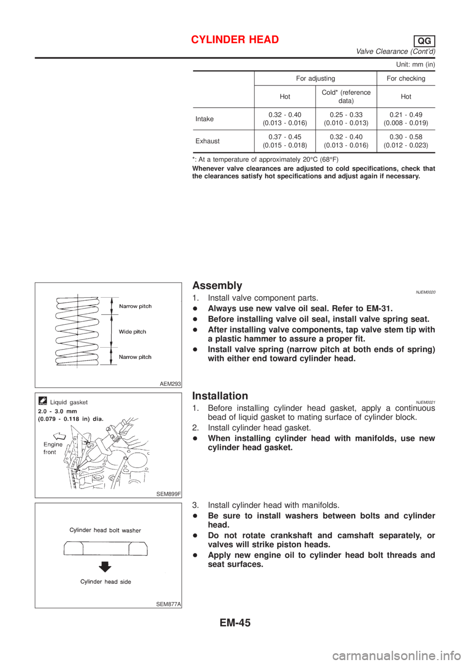
Unit: mm (in)
For adjusting For checking
HotCold* (reference
data)Hot
Intake0.32 - 0.40
(0.013 - 0.016)0.25 - 0.33
(0.010 - 0.013)0.21 - 0.49
(0.008 - 0.019)
Exhaust0.37 - 0.45
(0.015 - 0.018)0.32 - 0.40
(0.013 - 0.016)0.30 - 0.58
(0.012 - 0.023)
*: At a temperature of approximately 20ÉC (68ÉF)
Whenever valve clearances are adjusted to cold specifications, check that
the clearances satisfy hot specifications and adjust again if necessary.
AEM293
AssemblyNJEM00201. Install valve component parts.
+Always use new valve oil seal. Refer to EM-31.
+Before installing valve oil seal, install valve spring seat.
+After installing valve components, tap valve stem tip with
a plastic hammer to assure a proper fit.
+Install valve spring (narrow pitch at both ends of spring)
with either end toward cylinder head.
SEM899F
InstallationNJEM00211. Before installing cylinder head gasket, apply a continuous
bead of liquid gasket to mating surface of cylinder block.
2. Install cylinder head gasket.
+When installing cylinder head with manifolds, use new
cylinder head gasket.
SEM877A
3. Install cylinder head with manifolds.
+Be sure to install washers between bolts and cylinder
head.
+Do not rotate crankshaft and camshaft separately, or
valves will strike piston heads.
+Apply new engine oil to cylinder head bolt threads and
seat surfaces.
CYLINDER HEADQG
Valve Clearance (Cont'd)
EM-45
Page 125 of 2493

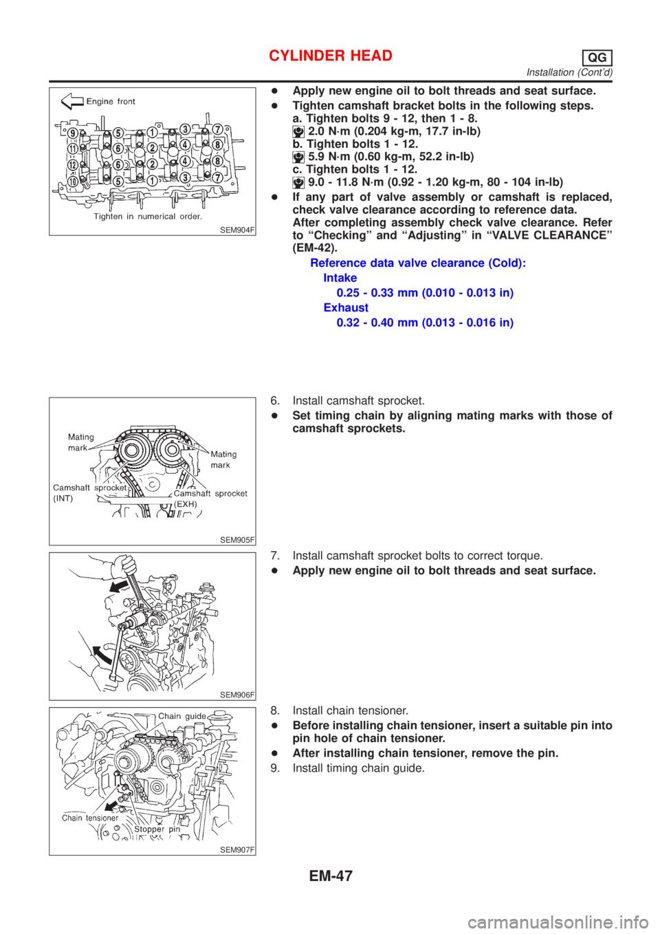
SEM904F
+Apply new engine oil to bolt threads and seat surface.
+Tighten camshaft bracket bolts in the following steps.
a. Tighten bolts9-12,then1-8.
2.0 N´m (0.204 kg-m, 17.7 in-lb)
b. Tighten bolts1-12.
5.9 N´m (0.60 kg-m, 52.2 in-lb)
c. Tighten bolts1-12.
9.0 - 11.8 N´m (0.92 - 1.20 kg-m, 80 - 104 in-lb)
+If any part of valve assembly or camshaft is replaced,
check valve clearance according to reference data.
After completing assembly check valve clearance. Refer
to ªCheckingº and ªAdjustingº in ªVALVE CLEARANCEº
(EM-42).
Reference data valve clearance (Cold):
Intake
0.25 - 0.33 mm (0.010 - 0.013 in)
Exhaust
0.32 - 0.40 mm (0.013 - 0.016 in)
SEM905F
6. Install camshaft sprocket.
+Set timing chain by aligning mating marks with those of
camshaft sprockets.
SEM906F
7. Install camshaft sprocket bolts to correct torque.
+Apply new engine oil to bolt threads and seat surface.
SEM907F
8. Install chain tensioner.
+Before installing chain tensioner, insert a suitable pin into
pin hole of chain tensioner.
+After installing chain tensioner, remove the pin.
9. Install timing chain guide.
CYLINDER HEADQG
Installation (Cont'd)
EM-47
Page 126 of 2493
SEM887F
10. Install cylinder head front cover.
+Apply liquid gasket to cylinder head front cover.
+Use Genuine Liquid Gasket or equivalent.
SEM889F
11. Install camshaft position sensor (PHASE).
SEM888F
12. Before installing rocker cover, apply a continuous bead of liq-
uid gasket to mating surface of cylinder head.
SEM105G
13. Install rocker cover with rocker cover gasket and tighten bolts
in numerical order as shown in the figure.
14. Install spark plugs.
15. Install ignition coils.
16. Install exhaust manifold.
17. Install intake manifold rear supports.
18. Connect vacuum hoses, fuel hoses, water hose, wire, harness,
connectors and so on.
19. Install front exhaust tube.
20. Install front undercovers.
21. Install air duct to intake manifold collector.
22. Drive belts.
For adjusting drive belt deflection, refer to ªCheckingº, EM-15.
23. Reinstall parts in reverse order of removal.
CYLINDER HEADQG
Installation (Cont'd)
EM-48
Page 163 of 2493

+If the belt deflection of the current belt is out of the ªLimit
for re-tighteningº, adjust to the ªAdjusted valueº.
+When checking belt deflection immediately after
installation, first adjust it to the specified value. Then,
after turning crankshaft two turns or more, re-adjust it to
the specified value to avoid variation in deflection
between pulleys.
+Make sure the belts are fully fitted into the pulley grooves
during installation.
+Handle with care to avoid smearing the belts with oil or
cooling water etc.
+Do not twist or bend the belts with strong force.
JEM251G
AIR CONDITIONER COMPRESSOR BELTNJEM0089S011. Remove RH splash cover (with undercover attached).
2. Loosen idler pulley lock nut (A).
3. Turn adjusting bolt (B) to adjust.
+Refer to EM-84, ªInspectionº for adjustment values.
4. Tighten lock nut (A).
Nut A:
: 31 - 39 N´m (3.1 - 4.0 kg-m, 23 - 28 ft-lb)
ALTERNATOR & WATER PUMP BELTNJEM0089S021. Loosen adjuster lock nut (C).
2. Loosen alternator fixing bolts (D) (each on front and rear).
3. Turn adjusting bolt (E) to adjust.
+Refer to EM-84, ªInspectionº for adjustment values.
4. Tighten nut (C) and bolt (D) in this order.
Nut C:
: 19 - 24 N´m (1.9 - 2.5 kg-m, 14 - 18 ft-lb)
Bolt D:
: 44 - 57 N´m (4.4 - 5.9 kg-m, 32 - 42 ft-lb)
RemovalNJEM00901. Loosen each belt. Refer to EM-84, ªAdjustmentº.
2. Remove air conditioner compressor belt.
3. Remove alternator & water pump belt.
DRIVE BELTSYD
Adjustment (Cont'd)
EM-85
Page 193 of 2493

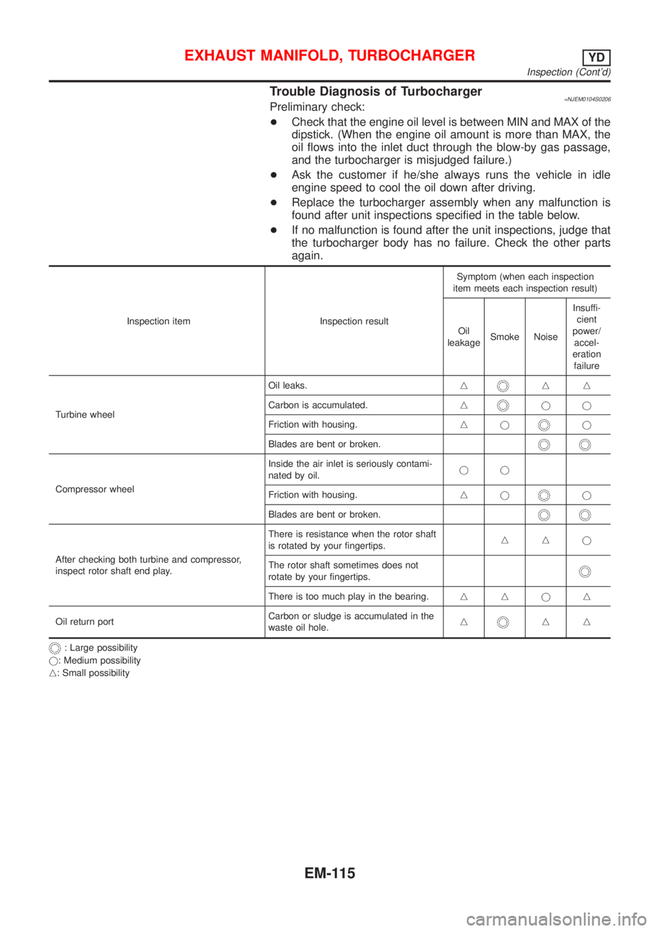
Trouble Diagnosis of Turbocharger=NJEM0104S0206Preliminary check:
+Check that the engine oil level is between MIN and MAX of the
dipstick. (When the engine oil amount is more than MAX, the
oil flows into the inlet duct through the blow-by gas passage,
and the turbocharger is misjudged failure.)
+Ask the customer if he/she always runs the vehicle in idle
engine speed to cool the oil down after driving.
+Replace the turbocharger assembly when any malfunction is
found after unit inspections specified in the table below.
+If no malfunction is found after the unit inspections, judge that
the turbocharger body has no failure. Check the other parts
again.
Inspection item Inspection resultSymptom (when each inspection
item meets each inspection result)
Oil
leakageSmoke NoiseInsuffi-
cient
power/
accel-
eration
failure
Turbine wheelOil leaks.n
nn
Carbon is accumulated.n
jj
Friction with housing.nj
j
Blades are bent or broken.
Compressor wheelInside the air inlet is seriously contami-
nated by oil.jj
Friction with housing.njj
Blades are bent or broken.
After checking both turbine and compressor,
inspect rotor shaft end play.There is resistance when the rotor shaft
is rotated by your fingertips.nnj
The rotor shaft sometimes does not
rotate by your fingertips.
There is too much play in the bearing.nnjn
Oil return portCarbon or sludge is accumulated in the
waste oil hole.n
nn
: Large possibility
j: Medium possibility
n: Small possibility
EXHAUST MANIFOLD, TURBOCHARGERYD
Inspection (Cont'd)
EM-115