2001 NISSAN ALMERA N16 EC-163
[x] Cancel search: EC-163Page 306 of 2493

Alphabetical & P No. Index for DTCNJEC0001Check if the vehicle is a model with the Euro-OBD (E-OBD) system or not by referring to the ªType approval
numberº on the identification plate.
Refer to GI-40, ªIDENTIFICATION PLATEº.
Type approval number Model
Available With Euro-OBD system
Not available Without Euro-OBD system
MODELS WITH EURO-OBD SYSTEMNJEC0001S03Alphabetical Index for DTCNJEC0001S0301
Items
(CONSULT-II screen terms)DTC*6
Reference page
CONSULT-II
GST*2ECM*1*7
Unable to access ECM Ð Ð EC-123
AIR TEMP SEN/CIRC P0110 0110 EC-158
A/T 1ST GR FNCTN P0731 0731 AT-202
A/T 2ND GR FNCTN P0732 0732 AT-209
A/T 3RD GR FNCTN P0733 0733 AT-215
A/T 4TH GR FNCTN P0734 0734 AT-221
A/T DIAG COMM LINE P1605 1605 EC-361
ATF TEMP SEN/CIRC P0710 0710 AT-187
CMP SEN/CIRCUIT P0340 0340 EC-278
CLOSED TP SW/CIRC*7 P0510 0510 EC-321
COOLANT T SEN/CIRC*3 P0115 0115 EC-163
CKP SEN/CIRCUIT P0335 0335 EC-272
CYL 1 MISFIRE P0301 0301 EC-262
CYL 2 MISFIRE P0302 0302 EC-262
CYL 3 MISFIRE P0303 0303 EC-262
CYL 4 MISFIRE P0304 0304 EC-262
ECM P0605 0605 EC-327
EGR SYSTEM*7 P0400 0400 EC-285
EGR SYSTEM*7 P1402 1402 EC-353
EGR TEMP SEN/CIRC*7 P1401 1401 EC-347
EGR VOL CON/V CIR*7 P0403 0403 EC-293
ENGINE SPEED SIG P0725 0725 AT-198
ENG OVER TEMP P1217 1217 EC-334
FUEL SYS-LEAN/BK1 P0171 0171 EC-248
FUEL SYS-RICH/BK1 P0172 0172 EC-255
HO2S1 HTR (B1) P0135 0135 EC-209
HO2S1 (B1) P0130 0130 EC-176
HO2S1 (B1) P0131 0131 EC-183
TROUBLE DIAGNOSIS Ð INDEXQG
Alphabetical & P No. Index for DTC
EC-10
Page 308 of 2493

P No. Index for DTCNJEC0001S0302
DTC*6
Items
(CONSULT-II screen terms)Reference page
CONSULT-II
GST*2ECM*1*7
Ð Ð Unable to access ECM EC-123
Ð Flashing*5NO DTC IS DETECTED.
FURTHER TESTING MAYBE REQUIRED.EC-73
Ð 0000NO DTC IS DETECTED.
FURTHER TESTING MAYBE REQUIRED.Ð
P0100 0100 MAF SEN/CIRCUIT*3 EC-152
P0110 0110 AIR TEMP SEN/CIRC EC-158
P0115 0115 COOLANT T SEN/CIRC*3 EC-163
P0120 0120 THRTL POS SEN/CIRC*3 EC-168
P0130 0130 HO2S1 (B1) EC-176
P0131 0131 HO2S1 (B1) EC-183
P0132 0132 HO2S1 (B1) EC-189
P0133 0133 HO2S1 (B1) EC-195
P0134 0134 HO2S1 (B1) EC-203
P0135 0135 HO2S1 HTR (B1) EC-209
P0137 0137 HO2S2 (B1) EC-214
P0138 0138 HO2S2 (B1) EC-222
P0139 0139 HO2S2 (B1) EC-229
P0140 0140 HO2S2 (B1) EC-237
P0141 0141 HO2S2 HTR (B1) EC-243
P0171 0171 FUEL SYS-LEAN/BK1 EC-248
P0172 0172 FUEL SYS-RICH/BK1 EC-255
P0300 0300 MULTI CYL MISFIRE EC-262
P0301 0301 CYL 1 MISFIRE EC-262
P0302 0302 CYL 2 MISFIRE EC-262
P0303 0303 CYL 3 MISFIRE EC-262
P0304 0304 CYL 4 MISFIRE EC-262
P0325 0325 KNOCK SEN/CIRC-B1 EC-268
P0335 0335 CKP SEN/CIRCUIT EC-272
P0340 0340 CMP SEN/CIRCUIT EC-278
P0400 0400 EGR SYSTEM*7 EC-285
P0403 0403 EGR VOL CON/V CIR*7 EC-293
P0420 0420 TW CATALYST SYS-B1 EC-299
P0443 0443 PURG VOLUME CONT/V EC-304
P0500 0500 VEH SPEED SEN/CIRC*4 EC-309
P0505 0505 IACV/AAC VLV/CIRC EC-313
TROUBLE DIAGNOSIS Ð INDEXQG
Alphabetical & P No. Index for DTC (Cont'd)
EC-12
Page 310 of 2493

Items
(CONSULT-II screen terms)DTC*6
Reference page
CONSULT-II
GST*2ECM*1
COOLANT T SEN/CIRC*3 P0115 0115 EC-163
ENG OVER TEMP P1217 1217 EC-334
HO2S1 (B1) P0130 0130 EC-176
KNOCK SEN/CIRC-B1 P0325 0325 EC-268
MAF SEN/CIRCUIT*3 P0100 0100 EC-152
NATS MALFUNCTION P1610 - P1615 1610 - 1615 EL-239
NO DTC IS DETECTED.
FURTHER TESTING MAYBE REQUIREDÐ 0000 Ð
NO DTC IS DETECTED.
FURTHER TESTING MAYBE REQUIREDÐ Flashing*5 EC-73
THRTL POS SEN/CIRC*3 P0120 0120 EC-168
VEH SPEED SEN/CIRC*4 P0500 0500 EC-309
*1: In Diagnostic Test Mode II (Self-diagnostic results) (If so equipped). These numbers are controlled by NISSAN.
*2: These numbers are prescribed by ISO 15031-6.
*3: When the fail-safe operation occurs, the MI illuminates.
*4: The MI illuminates when the ªRevolution sensor signalº and the ªVehicle speed sensor signalº meet the fail-safe condition at the
same time.
*5: While engine is running.
*6: 1st trip DTC No. is the same as DTC No.
P No. Index for DTCNJEC0001S0402
DTC*6
Items
(CONSULT-II screen terms)Reference page
CONSULT-II
GST*2ECM*1
Ð Ð Unable to access ECM EC-123
Ð Flashing*5NO DTC IS DETECTED.
FURTHER TESTING MAYBE REQUIRED.EC-73
Ð 0000NO DTC IS DETECTED.
FURTHER TESTING MAYBE REQUIRED.Ð
P0100 0100 MAF SEN/CIRCUIT*3 EC-152
P0115 0115 COOLANT T SEN/CIRC*3 EC-163
P0120 0120 THRTL POS SEN/CIRC*3 EC-168
P0130 0130 HO2S1 (B1) EC-176
P0325 0325 KNOCK SEN/CIRC-B1 EC-268
P0335 0335 CKP SEN/CIRCUIT EC-272
P0340 0340 CMP SEN/CIRCUIT EC-278
P0500 0500 VEH SPEED SEN/CIRC*4 EC-309
P1217 1217 ENG OVER TEMP EC-334
P1610 - 1615 1610 - 1615 NATS MALFUNCTION EL-239
*1: In Diagnostic Test Mode II (Self-diagnostic results) (If so equipped). These numbers are controlled by NISSAN.
*2: These numbers are prescribed by ISO 15031-6
*3: When the fail-safe operation occurs, the MI illuminates.
TROUBLE DIAGNOSIS Ð INDEXQG
Alphabetical & P No. Index for DTC (Cont'd)
EC-14
Page 347 of 2493

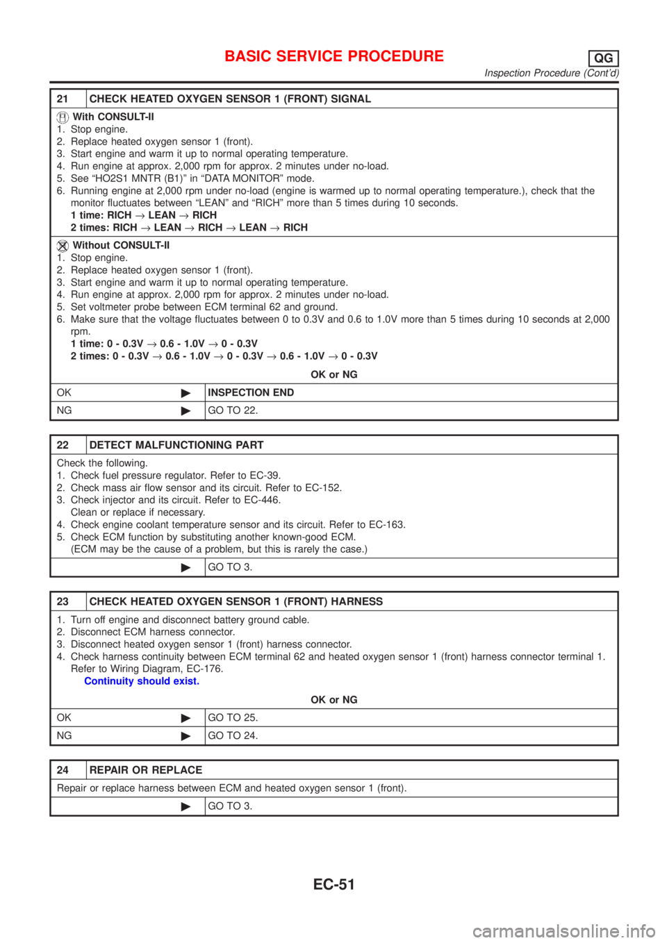
21 CHECK HEATED OXYGEN SENSOR 1 (FRONT) SIGNAL
With CONSULT-II
1. Stop engine.
2. Replace heated oxygen sensor 1 (front).
3. Start engine and warm it up to normal operating temperature.
4. Run engine at approx. 2,000 rpm for approx. 2 minutes under no-load.
5. See ªHO2S1 MNTR (B1)º in ªDATA MONITORº mode.
6. Running engine at 2,000 rpm under no-load (engine is warmed up to normal operating temperature.), check that the
monitor fluctuates between ªLEANº and ªRICHº more than 5 times during 10 seconds.
1 time: RICH®LEAN®RICH
2 times: RICH®LEAN®RICH®LEAN®RICH
Without CONSULT-II
1. Stop engine.
2. Replace heated oxygen sensor 1 (front).
3. Start engine and warm it up to normal operating temperature.
4. Run engine at approx. 2,000 rpm for approx. 2 minutes under no-load.
5. Set voltmeter probe between ECM terminal 62 and ground.
6. Make sure that the voltage fluctuates between 0 to 0.3V and 0.6 to 1.0V more than 5 times during 10 seconds at 2,000
rpm.
1 time: 0 - 0.3V®0.6 - 1.0V®0 - 0.3V
2 times: 0 - 0.3V®0.6 - 1.0V®0 - 0.3V®0.6 - 1.0V®0 - 0.3V
OK or NG
OK©INSPECTION END
NG©GO TO 22.
22 DETECT MALFUNCTIONING PART
Check the following.
1. Check fuel pressure regulator. Refer to EC-39.
2. Check mass air flow sensor and its circuit. Refer to EC-152.
3. Check injector and its circuit. Refer to EC-446.
Clean or replace if necessary.
4. Check engine coolant temperature sensor and its circuit. Refer to EC-163.
5. Check ECM function by substituting another known-good ECM.
(ECM may be the cause of a problem, but this is rarely the case.)
©GO TO 3.
23 CHECK HEATED OXYGEN SENSOR 1 (FRONT) HARNESS
1. Turn off engine and disconnect battery ground cable.
2. Disconnect ECM harness connector.
3. Disconnect heated oxygen sensor 1 (front) harness connector.
4. Check harness continuity between ECM terminal 62 and heated oxygen sensor 1 (front) harness connector terminal 1.
Refer to Wiring Diagram, EC-176.
Continuity should exist.
OK or NG
OK©GO TO 25.
NG©GO TO 24.
24 REPAIR OR REPLACE
Repair or replace harness between ECM and heated oxygen sensor 1 (front).
©GO TO 3.
BASIC SERVICE PROCEDUREQG
Inspection Procedure (Cont'd)
EC-51
Page 350 of 2493

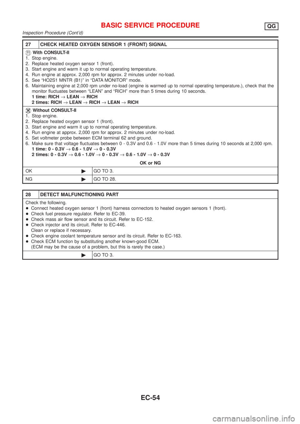
27 CHECK HEATED OXYGEN SENSOR 1 (FRONT) SIGNAL
With CONSULT-II
1. Stop engine.
2. Replace heated oxygen sensor 1 (front).
3. Start engine and warm it up to normal operating temperature.
4. Run engine at approx. 2,000 rpm for approx. 2 minutes under no-load.
5. See ªHO2S1 MNTR (B1)º in ªDATA MONITORº mode.
6. Maintaining engine at 2,000 rpm under no-load (engine is warmed up to normal operating temperature.), check that the
monitor fluctuates between ªLEANº and ªRICHº more than 5 times during 10 seconds.
1 time: RICH®LEAN®RICH
2 times: RICH®LEAN®RICH®LEAN®RICH
Without CONSULT-II
1. Stop engine.
2. Replace heated oxygen sensor 1 (front).
3. Start engine and warm it up to normal operating temperature.
4. Run engine at approx. 2,000 rpm for approx. 2 minutes under no-load.
5. Set voltmeter probe between ECM terminal 62 and ground.
6. Make sure that voltage fluctuates between 0 - 0.3V and 0.6 - 1.0V more than 5 times during 10 seconds at 2,000 rpm.
1 time: 0 - 0.3V®0.6 - 1.0V®0 - 0.3V
2 times: 0 - 0.3V®0.6 - 1.0V®0 - 0.3V®0.6 - 1.0V®0 - 0.3V
OK or NG
OK©GO TO 3.
NG©GO TO 28.
28 DETECT MALFUNCTIONING PART
Check the following.
+Connect heated oxygen sensor 1 (front) harness connectors to heated oxygen sensors 1 (front).
+Check fuel pressure regulator. Refer to EC-39.
+Check mass air flow sensor and its circuit. Refer to EC-152.
+Check injector and its circuit. Refer to EC-446.
Clean or replace if necessary.
+Check engine coolant temperature sensor and its circuit. Refer to EC-163.
+Check ECM function by substituting another known-good ECM.
(ECM may be the cause of a problem, but this is rarely the case.)
©GO TO 3.
BASIC SERVICE PROCEDUREQG
Inspection Procedure (Cont'd)
EC-54
Page 362 of 2493

SRT item Self-diagnostic test itemTest value (GST display)
Test limit Application
TID CID
HO2SHeated oxygen sensor 1
(front)09H 04H Max. X
0AH 84H Min. X
0BH 04H Max. X
0CH 04H Max. X
0DH 04H Max. X
Heated oxygen sensor 2
(rear)19H 86H Min. X
1AH 86H Min. X
1BH 06H Max. X
1CH 06H Max. X
HO2S HTRHeated oxygen sensor 1
heater (front)29H 08H Max. X
2AH 88H Min. X
Heated oxygen sensor 2
heater (rear)2DH 0AH Max. X
2EH 8AH Min. X
EGR SYSTEM
(where fitted)EGR function31H 8CH Min. X
32H 8CH Min. X
33H 8CH Min. X
34H 8CH Min. X
35H 0CH Max. X
Emission-related Diagnostic Information ItemsNJEC0031S0105X: Applicable Ð: Not applicable
Items
(CONSULT-II screen terms)DTC*1 SRT codeTest value/Test
limit
(GST only)1st trip DTC*1 Reference page
NO SELF DIAGNOSTIC FAIL-
URE INDICATEDP0000ÐÐÐÐ
MAF SEN/CIRCUIT P0100 Ð Ð X EC-152
AIR TEMP SEN/CIRC P0110 Ð Ð X EC-158
COOLANT T SEN/CIRC P0115 Ð Ð X EC-163
THRTL POS SEN/CIRC P0120 Ð Ð X EC-168
HO2S1 (B1) P0130 X X X*2 EC-176
HO2S1 (B1) P0131 X X X*2 EC-183
HO2S1 (B1) P0132 X X X*2 EC-189
HO2S1 (B1) P0133 X X X*2 EC-195
HO2S1 (B1) P0134 X X X*2 EC-203
HO2S1 HTR (B1) P0135 X X X*2 EC-209
HO2S2 (B1) P0137 X X X*2 EC-214
HO2S2 (B1) P0138 X X X*2 EC-222
HO2S2 (B1) P0139 X X X*2 EC-229
ON BOARD DIAGNOSTIC SYSTEM DESCRIPTIONQG
Emission-related Diagnostic Information (Cont'd)
EC-66
Page 421 of 2493

SYMPTOM
Reference
page
HARD/NO START/RESTART (EXCP. HA)
ENGINE STALL
HESITATION/SURGING/FLAT SPOT
SPARK KNOCK/DETONATION
LACK OF POWER/POOR ACCELERATION
HIGH IDLE/LOW IDLE
ROUGH IDLE/HUNTING
IDLING VIBRATION
SLOW/NO RETURN TO IDLE
OVERHEATS/WATER TEMPERATURE HIGH
EXCESSIVE FUEL CONSUMPTION
EXCESSIVE OIL CONSUMPTION
BATTERY DEAD (UNDER CHARGE)
Warranty symptom code AA AB AC AD AE AF AG AH AJ AK AL AM HA
Crankshaft position sensor (POS)
circuit22EC-272
Camshaft position sensor
(PHASE) circuit3 2 3 EC-278
Mass air flow sensor circuit11222 22 2EC-152
Heated oxygen sensor 1 (front)
circuit1232 22 2EC-176,
183
Engine coolant temperature sen-
sor circuit112323223 2EC-163,
165
Throttle position sensor circuit 1 222222 2EC-168
Incorrect throttle position sensor
adjustment31 11111 1EC-98
Vehicle speed sensor circuit 2 3 3 3 EC-309
Knock sensor circuit 2 3 EC-268
ECM 22333333333EC-327,
123
Start signal circuit 2EC-461
PNP switch circuit 3 3 3 3 3 EC-364
Power steering oil pressure switch
circuit2 3 3 EC-471
Electrical load signal circuit 3 3 EC-480
1 - 6: The numbers refer to the order of inspection.
(continued on next page)
TROUBLE DIAGNOSIS Ð GENERAL DESCRIPTIONQG
Symptom Matrix Chart (Cont'd)
EC-125
Page 458 of 2493

5 CHECK INTAKE AIR TEMPERATURE SENSOR
Refer to ªComponent Inspectionº, EC-163.
OK or NG
OK©GO TO 6.
NG©Replace intake air temperature sensor.
6 CHECK INTERMITTENT INCIDENT
Perform ªTROUBLE DIAGNOSIS FOR INTERMITTENT INCIDENTº, EC-144.
©INSPECTION END
SEC516C
Component InspectionNJEC0071INTAKE AIR TEMPERATURE SENSORNJEC0071S01Check resistance between mass air flow sensor harness connec-
tor terminals 3 and 5.
Intake air temperature
ÉC (ÉF)Resistance kW
25 (77) 1.9 - 2.1
If NG, replace intake air temperature sensor.
DTC P0110 INTAKE AIR TEMPERATURE SENSORQG
Diagnostic Procedure (Cont'd)
EC-162