2001 NISSAN ALMERA N16 nats malfunction
[x] Cancel search: nats malfunctionPage 297 of 2493

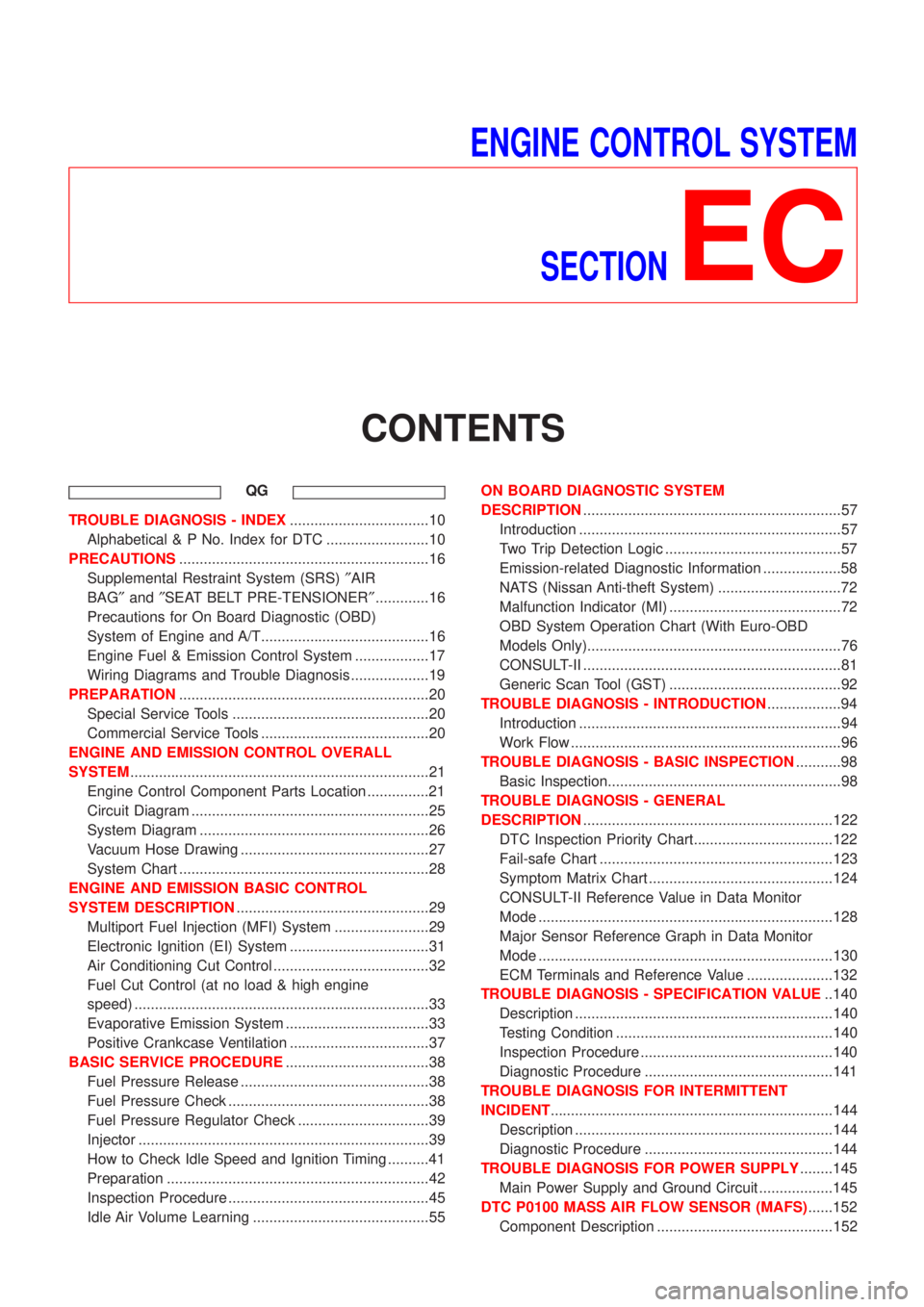
ENGINE CONTROL SYSTEM
SECTION
EC
CONTENTS
QG
TROUBLE DIAGNOSIS - INDEX..................................10
Alphabetical & P No. Index for DTC .........................10
PRECAUTIONS.............................................................16
Supplemental Restraint System (SRS)²AIR
BAG²and²SEAT BELT PRE-TENSIONER².............16
Precautions for On Board Diagnostic (OBD)
System of Engine and A/T.........................................16
Engine Fuel & Emission Control System ..................17
Wiring Diagrams and Trouble Diagnosis ...................19
PREPARATION.............................................................20
Special Service Tools ................................................20
Commercial Service Tools .........................................20
ENGINE AND EMISSION CONTROL OVERALL
SYSTEM.........................................................................21
Engine Control Component Parts Location ...............21
Circuit Diagram ..........................................................25
System Diagram ........................................................26
Vacuum Hose Drawing ..............................................27
System Chart .............................................................28
ENGINE AND EMISSION BASIC CONTROL
SYSTEM DESCRIPTION...............................................29
Multiport Fuel Injection (MFI) System .......................29
Electronic Ignition (EI) System ..................................31
Air Conditioning Cut Control ......................................32
Fuel Cut Control (at no load & high engine
speed) ........................................................................33
Evaporative Emission System ...................................33
Positive Crankcase Ventilation ..................................37
BASIC SERVICE PROCEDURE...................................38
Fuel Pressure Release ..............................................38
Fuel Pressure Check .................................................38
Fuel Pressure Regulator Check ................................39
Injector .......................................................................39
How to Check Idle Speed and Ignition Timing ..........41
Preparation ................................................................42
Inspection Procedure .................................................45
Idle Air Volume Learning ...........................................55ON BOARD DIAGNOSTIC SYSTEM
DESCRIPTION...............................................................57
Introduction ................................................................57
Two Trip Detection Logic ...........................................57
Emission-related Diagnostic Information ...................58
NATS (Nissan Anti-theft System) ..............................72
Malfunction Indicator (MI) ..........................................72
OBD System Operation Chart (With Euro-OBD
Models Only)..............................................................76
CONSULT-II ...............................................................81
Generic Scan Tool (GST) ..........................................92
TROUBLE DIAGNOSIS - INTRODUCTION..................94
Introduction ................................................................94
Work Flow ..................................................................96
TROUBLE DIAGNOSIS - BASIC INSPECTION...........98
Basic Inspection.........................................................98
TROUBLE DIAGNOSIS - GENERAL
DESCRIPTION.............................................................122
DTC Inspection Priority Chart..................................122
Fail-safe Chart .........................................................123
Symptom Matrix Chart .............................................124
CONSULT-II Reference Value in Data Monitor
Mode ........................................................................128
Major Sensor Reference Graph in Data Monitor
Mode ........................................................................130
ECM Terminals and Reference Value .....................132
TROUBLE DIAGNOSIS - SPECIFICATION VALUE..140
Description ...............................................................140
Testing Condition .....................................................140
Inspection Procedure ...............................................140
Diagnostic Procedure ..............................................141
TROUBLE DIAGNOSIS FOR INTERMITTENT
INCIDENT.....................................................................144
Description ...............................................................144
Diagnostic Procedure ..............................................144
TROUBLE DIAGNOSIS FOR POWER SUPPLY........145
Main Power Supply and Ground Circuit ..................145
DTC P0100 MASS AIR FLOW SENSOR (MAFS)......152
Component Description ...........................................152
Page 307 of 2493

Items
(CONSULT-II screen terms)DTC*6
Reference page
CONSULT-II
GST*2ECM*1*7
HO2S1 (B1) P0132 0132 EC-189
HO2S1 (B1) P0133 0133 EC-195
HO2S1 (B1) P0134 0134 EC-203
HO2S2 (B1) P0137 0137 EC-214
HO2S2 (B1) P0138 0138 EC-222
HO2S2 (B1) P0139 0139 EC-229
HO2S2 (B1) P0140 0140 EC-237
HO2S2 HTR (B1) P0141 0141 EC-243
IACV/AAC VLV/CIRC P0505 0505 EC-313
INT/V TIM V/CIR-B1 P1111 1111EC-329
KNOCK SEN/CIRC-B1 P0325 0325 EC-268
L/PRESS SOL/CIRC P0745 0745 AT-237
MAF SEN/CIRCUIT*3 P0100 0100 EC-152
MULTI CYL MISFIRE P0300 0300 EC-262
NATS MALFUNCTION P1610 - P1615 1610 - 1615 EL-239
NO DTC IS DETECTED.
FURTHER TESTING MAYBE REQUIREDÐ 0000 Ð
NO DTC IS DETECTED.
FURTHER TESTING MAYBE REQUIREDÐ Flashing*5 EC-73
O/R CLTCH SOL/CIRC P1760 1760 AT-265
PNP SW/CIRC P0705 0705 AT-181
P-N POS SW/CIRCUIT P1706 1706 EC-364
PURG VOLUME CONT/V P0443 0443 EC-304
SFT SOL A/CIRC P0750 0750 AT-244
SFT SOL B/CIRC P0755 0755 AT-250
TCC SOLENOID/CIRC P0740 0740 AT-231
THRTL POS SEN/CIRC*3 P0120 0120 EC-168
TP SEN/CIRC A/T P1705 1705 AT-256
TW CATALYST SYS-B1 P0420 0420 EC-299
VEH SPD SEN/CIR AT P0720 0720 AT-193
VEH SPEED SEN/CIRC*4 P0500 0500 EC-309
*1: In Diagnostic Test Mode II (Self-diagnostic results). These numbers are controlled by NISSAN.
*2: These numbers are prescribed by ISO 15031-6.
*3: When the fail-safe operation occurs, the MI illuminates.
*4: The MI illuminates when the ªRevolution sensor signalº and the ªVehicle speed sensor signalº meet the fail-safe condition at the
same time.
*5: While engine is running.
*6: 1st trip DTC No. is the same as DTC No.
*7: If so equipped
TROUBLE DIAGNOSIS Ð INDEXQG
Alphabetical & P No. Index for DTC (Cont'd)
EC-11
Page 309 of 2493

DTC*6
Items
(CONSULT-II screen terms)Reference page
CONSULT-II
GST*2ECM*1*7
P0510 0510 CLOSED TP SW/CIRC*7 EC-321
P0605 0605 ECM EC-327
P0705 0705 PNP SW/CIRC AT-181
P0710 0710 ATF TEMP SEN/CIRC AT-187
P0720 0720 VEH SPD SEN/CIR AT AT-193
P0725 0725 ENGINE SPEED SIG AT-198
P0731 0731 A/T 1ST GR FNCTN AT-202
P0732 0732 A/T 2ND GR FNCTN AT-209
P0733 0733 A/T 3RD GR FNCTN AT-215
P0734 0734 A/T 4TH GR FNCTN AT-221
P0740 0740 TCC SOLENOID/CIRC AT-231
P0745 0745 L/PRESS SOL/CIRC AT-237
P0750 0750 SFT SOL A/CIRC AT-244
P0755 0755 SFT SOL B/CIRC AT-250
P 1111 1111INT/V TIM V/CIR-B1 EC-329
P1217 1217 ENG OVER TEMP EC-334
P1401 1401 EGR TEMP SEN/CIRC*7 EC-347
P1402 1402 EGR SYSTEM*7 EC-353
P1605 1605 A/T DIAG COMM LINE EC-361
P1610 - 1615 1610 - 1615 NATS MALFUNCTION EL-239
P1705 1705 TP SEN/CIRC A/T AT-256
P1706 1706 P-N POS SW/CIRCUIT EC-364
P1760 1760 O/R CLTCH SOL/CIRC AT-265
*1: In Diagnostic Test Mode II (Self-diagnostic results). These numbers are controlled by NISSAN.
*2: These numbers are prescribed by ISO 15031-6
*3: When the fail-safe operation occurs, the MI illuminates.
*4: The MI illuminates when the ªRevolution sensor signalº and the ªVehicle speed sensor signalº meet the fail-safe condition at the
same time.
*5: While engine is running.
*6: 1st trip DTC No. is the same as DTC No.
*7: If so equipped
MODELS WITHOUT EURO-OBD SYSTEMNJEC0001S04Alphabetical Index for DTCNJEC0001S0401
Items
(CONSULT-II screen terms)DTC*6
Reference page
CONSULT-II
GST*2ECM*1
Unable to access ECM Ð Ð EC-123
CKP SEN/CIRCUIT P0335 0335 EC-272
CMP SEN/CIRCUIT P0340 0340 EC-278
TROUBLE DIAGNOSIS Ð INDEXQG
Alphabetical & P No. Index for DTC (Cont'd)
EC-13
Page 310 of 2493

Items
(CONSULT-II screen terms)DTC*6
Reference page
CONSULT-II
GST*2ECM*1
COOLANT T SEN/CIRC*3 P0115 0115 EC-163
ENG OVER TEMP P1217 1217 EC-334
HO2S1 (B1) P0130 0130 EC-176
KNOCK SEN/CIRC-B1 P0325 0325 EC-268
MAF SEN/CIRCUIT*3 P0100 0100 EC-152
NATS MALFUNCTION P1610 - P1615 1610 - 1615 EL-239
NO DTC IS DETECTED.
FURTHER TESTING MAYBE REQUIREDÐ 0000 Ð
NO DTC IS DETECTED.
FURTHER TESTING MAYBE REQUIREDÐ Flashing*5 EC-73
THRTL POS SEN/CIRC*3 P0120 0120 EC-168
VEH SPEED SEN/CIRC*4 P0500 0500 EC-309
*1: In Diagnostic Test Mode II (Self-diagnostic results) (If so equipped). These numbers are controlled by NISSAN.
*2: These numbers are prescribed by ISO 15031-6.
*3: When the fail-safe operation occurs, the MI illuminates.
*4: The MI illuminates when the ªRevolution sensor signalº and the ªVehicle speed sensor signalº meet the fail-safe condition at the
same time.
*5: While engine is running.
*6: 1st trip DTC No. is the same as DTC No.
P No. Index for DTCNJEC0001S0402
DTC*6
Items
(CONSULT-II screen terms)Reference page
CONSULT-II
GST*2ECM*1
Ð Ð Unable to access ECM EC-123
Ð Flashing*5NO DTC IS DETECTED.
FURTHER TESTING MAYBE REQUIRED.EC-73
Ð 0000NO DTC IS DETECTED.
FURTHER TESTING MAYBE REQUIRED.Ð
P0100 0100 MAF SEN/CIRCUIT*3 EC-152
P0115 0115 COOLANT T SEN/CIRC*3 EC-163
P0120 0120 THRTL POS SEN/CIRC*3 EC-168
P0130 0130 HO2S1 (B1) EC-176
P0325 0325 KNOCK SEN/CIRC-B1 EC-268
P0335 0335 CKP SEN/CIRCUIT EC-272
P0340 0340 CMP SEN/CIRCUIT EC-278
P0500 0500 VEH SPEED SEN/CIRC*4 EC-309
P1217 1217 ENG OVER TEMP EC-334
P1610 - 1615 1610 - 1615 NATS MALFUNCTION EL-239
*1: In Diagnostic Test Mode II (Self-diagnostic results) (If so equipped). These numbers are controlled by NISSAN.
*2: These numbers are prescribed by ISO 15031-6
*3: When the fail-safe operation occurs, the MI illuminates.
TROUBLE DIAGNOSIS Ð INDEXQG
Alphabetical & P No. Index for DTC (Cont'd)
EC-14
Page 368 of 2493

SEF543X
NATS (Nissan Anti-theft System)NJEC0591+If the security indicator lights up with the ignition switch
in the ªONº position or ªNATS MALFUNCTIONº is dis-
played on ªSELF-DIAG RESULTSº screen, perform self-
diagnostic results mode with CONSULT-II using NATS pro-
gram card. Refer to NATS (Nissan Anti-Theft System) in EL
section.
+Confirm no self-diagnostic results of NATS is displayed
before touching ªERASEº in ªSELF-DIAG RESULTSº
mode with CONSULT-II.
+When replacing ECM, initialization of NATS system and
registration of all NATS ignition key IDs must be carried
out with CONSULT-II using NATS program card.
Therefore, be sure to receive all keys from vehicle owner.
Regarding the procedure of NATS initialization and NATS
ignition key ID registration, refer to CONSULT-II operation
manual, NATS.
Malfunction Indicator (MI)
DESCRIPTIONNJEC0032
SAT652J
The MI is located on the instrument panel.
1. The MI will light up when the ignition switch is turned ON without the engine running. This is a bulb check.
+If the MI does not light up, refer to EL-107, ªWARNING LAMPSº or see EC-488.
2. When the engine is started, the MI should go off.
If the MI remains on, the on board diagnostic system has detected an engine system malfunction.
On Board Diagnostic System FunctionNJEC0032S01The on board diagnostic system has the following four functions.
Diagnostic Test Mode I
1. BULB CHECK:
This function checks the MI bulb for damage (blown, open circuit, etc.).
If the MI does not come on, check MI circuit and ECM test mode selector. (See the following page.)
2. MALFUNCTION WARNING:
MI Condition
ON When the malfunction is detected or the ECM's CPU is malfunctioning.
OFF No malfunction.
Diagnostic Test Mode II (If so equipped)
ON BOARD DIAGNOSTIC SYSTEM DESCRIPTIONQG
NATS (Nissan Anti-theft System)
EC-72
Page 2346 of 2493

Component Parts and Harness Connetor
Location
NJEL0406For details, refer to ªELECTRICAL UNIT LOCATIONº (EL-319) and
ªHARNESS LAYOUTº (EL-324).
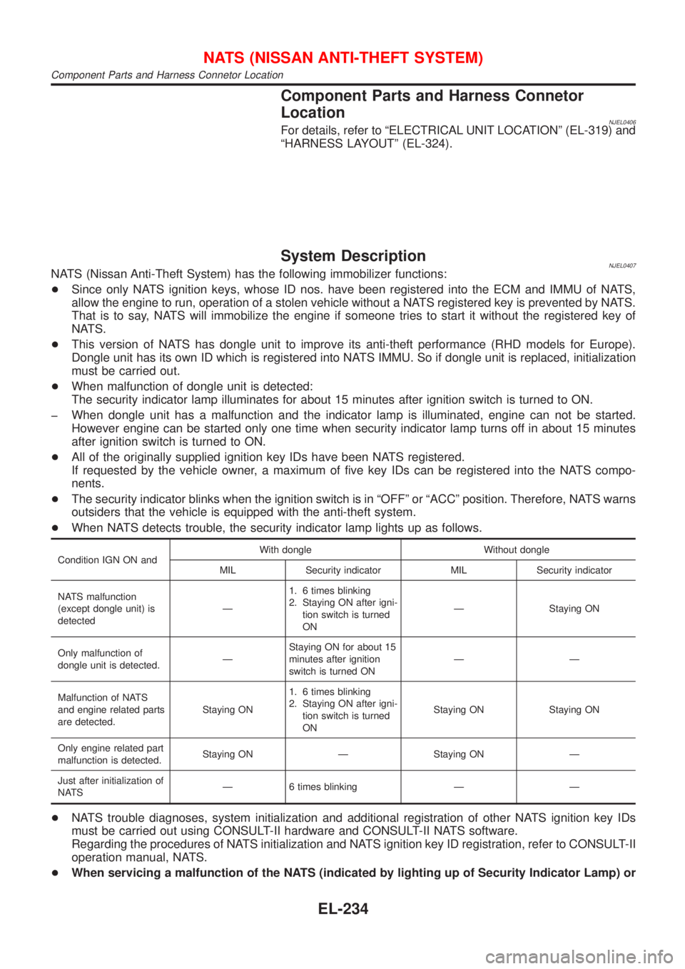
System DescriptionNJEL0407NATS (Nissan Anti-Theft System) has the following immobilizer functions:
+Since only NATS ignition keys, whose ID nos. have been registered into the ECM and IMMU of NATS,
allow the engine to run, operation of a stolen vehicle without a NATS registered key is prevented by NATS.
That is to say, NATS will immobilize the engine if someone tries to start it without the registered key of
NATS.
+This version of NATS has dongle unit to improve its anti-theft performance (RHD models for Europe).
Dongle unit has its own ID which is registered into NATS IMMU. So if dongle unit is replaced, initialization
must be carried out.
+When malfunction of dongle unit is detected:
The security indicator lamp illuminates for about 15 minutes after ignition switch is turned to ON.
þ When dongle unit has a malfunction and the indicator lamp is illuminated, engine can not be started.
However engine can be started only one time when security indicator lamp turns off in about 15 minutes
after ignition switch is turned to ON.
+All of the originally supplied ignition key IDs have been NATS registered.
If requested by the vehicle owner, a maximum of five key IDs can be registered into the NATS compo-
nents.
+The security indicator blinks when the ignition switch is in ªOFFº or ªACCº position. Therefore, NATS warns
outsiders that the vehicle is equipped with the anti-theft system.
+When NATS detects trouble, the security indicator lamp lights up as follows.
Condition IGN ON andWith dongle Without dongle
MIL Security indicator MIL Security indicator
NATS malfunction
(except dongle unit) is
detectedÐ1. 6 times blinking
2. Staying ON after igni-
tion switch is turned
ONÐ Staying ON
Only malfunction of
dongle unit is detected.ÐStaying ON for about 15
minutes after ignition
switch is turned ONÐÐ
Malfunction of NATS
and engine related parts
are detected.Staying ON1. 6 times blinking
2. Staying ON after igni-
tion switch is turned
ONStaying ON Staying ON
Only engine related part
malfunction is detected.Staying ON Ð Staying ON Ð
Just after initialization of
NATSÐ 6 times blinking Ð Ð
+NATS trouble diagnoses, system initialization and additional registration of other NATS ignition key IDs
must be carried out using CONSULT-II hardware and CONSULT-II NATS software.
Regarding the procedures of NATS initialization and NATS ignition key ID registration, refer to CONSULT-II
operation manual, NATS.
+When servicing a malfunction of the NATS (indicated by lighting up of Security Indicator Lamp) or
NATS (NISSAN ANTI-THEFT SYSTEM)
Component Parts and Harness Connetor Location
EL-234
Page 2351 of 2493

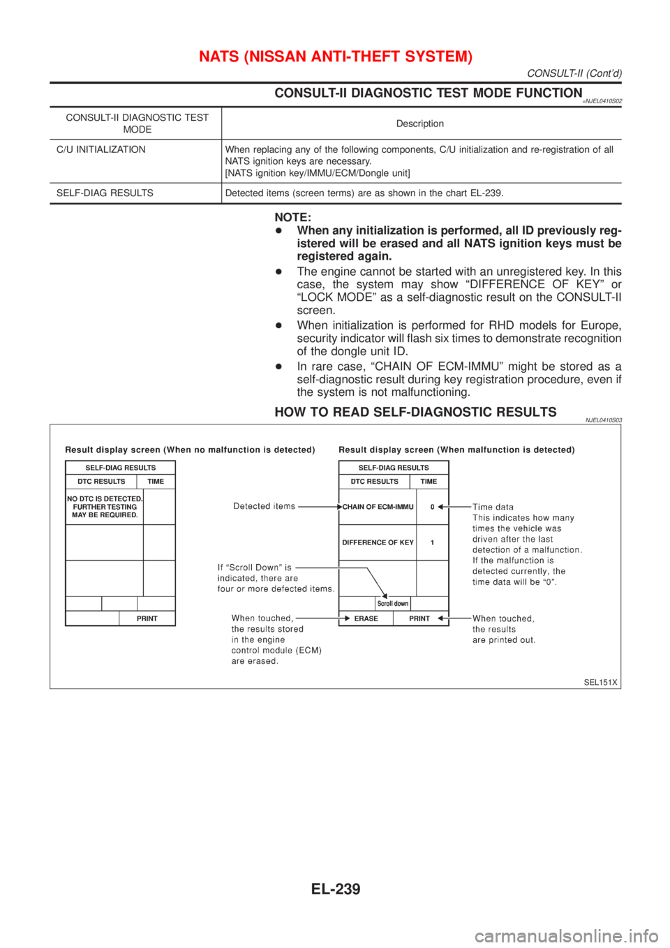
CONSULT-II DIAGNOSTIC TEST MODE FUNCTION=NJEL0410S02
CONSULT-II DIAGNOSTIC TEST
MODEDescription
C/U INITIALIZATION When replacing any of the following components, C/U initialization and re-registration of all
NATS ignition keys are necessary.
[NATS ignition key/IMMU/ECM/Dongle unit]
SELF-DIAG RESULTS Detected items (screen terms) are as shown in the chart EL-239.
NOTE:
+When any initialization is performed, all ID previously reg-
istered will be erased and all NATS ignition keys must be
registered again.
+The engine cannot be started with an unregistered key. In this
case, the system may show ªDIFFERENCE OF KEYº or
ªLOCK MODEº as a self-diagnostic result on the CONSULT-II
screen.
+When initialization is performed for RHD models for Europe,
security indicator will flash six times to demonstrate recognition
of the dongle unit ID.
+In rare case, ªCHAIN OF ECM-IMMUº might be stored as a
self-diagnostic result during key registration procedure, even if
the system is not malfunctioning.
HOW TO READ SELF-DIAGNOSTIC RESULTSNJEL0410S03
SEL151X
NATS (NISSAN ANTI-THEFT SYSTEM)
CONSULT-II (Cont'd)
EL-239
Page 2352 of 2493

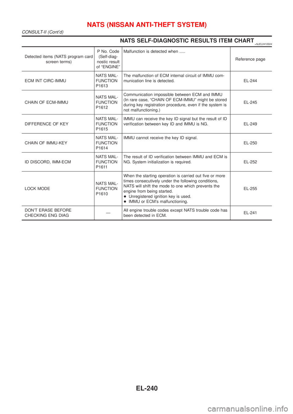
NATS SELF-DIAGNOSTIC RESULTS ITEM CHART=NJEL0410S04
Detected items (NATS program card
screen terms)P No. Code
(Self-diag-
nostic result
of ªENGINEºMalfunction is detected when .....
Reference page
ECM INT CIRC-IMMUNATS MAL-
FUNCTION
P1613The malfunction of ECM internal circuit of IMMU com-
munication line is detected. EL-244
CHAIN OF ECM-IMMUNATS MAL-
FUNCTION
P1612Communication impossible between ECM and IMMU
(In rare case, ªCHAIN OF ECM-IMMUº might be stored
during key registration procedure, even if the system is
not malfunctioning.)EL-245
DIFFERENCE OF KEYNATS MAL-
FUNCTION
P1615IMMU can receive the key ID signal but the result of ID
verification between key ID and IMMU is NG. EL-249
CHAIN OF IMMU-KEYNATS MAL-
FUNCTION
P1614IMMU cannot receive the key ID signal.
EL-250
ID DISCORD, IMM-ECMNATS MAL-
FUNCTION
P1611The result of ID verification between IMMU and ECM is
NG. System initialization is required. EL-252
LOCK MODENATS MAL-
FUNCTION
P1610When the starting operation is carried out five or more
times consecutively under the following conditions,
NATS will shift the mode to one which prevents the
engine from being started.
+Unregistered ignition key is used.
+IMMU or ECM's malfunctioning.EL-255
DON'T ERASE BEFORE
CHECKING ENG DIAGÐAll engine trouble codes except NATS trouble code has
been detected in ECM.EL-241
NATS (NISSAN ANTI-THEFT SYSTEM)
CONSULT-II (Cont'd)
EL-240