Page 103 of 2493
SEM008G
20. Remove cylinder head bolts at engine front side.
SEM879F
21. Remove oil pan. Refer to EM-19, ªRemovalº.
22. Remove oil strainer.
SEM880F
23. Remove starter motor, and set ring gear stopper using mount-
ing bolt holes.
SEM881F
24. Loosen crankshaft pulley bolt.
25. Remove crankshaft pulley with a suitable puller.
SEM103G
26. Remove RH engine mounting.
TIMING CHAINQG
Removal (Cont'd)
EM-25
Page 107 of 2493

SEM896F
12. Install front cover.
Bolt No. Tightening torque N´m (kg-m, in-lb) ª!º mm (in)
a. 6.9 - 9.5 (0.70 - 0.97, 61 - 84) 20 (0.79)
b. 6.9 - 9.5 (0.70 - 0.97, 61 - 84) 40 (1.57)
c. 17 - 24 (1.7 - 2.4, 148 - 208*) 70 (2.76)
d. 6.9 - 9.5 (0.70 - 0.97, 61 - 84) 72.8 (2.866)
e. 6.9 - 9.5 (0.70 - 0.97, 61 - 84) 12 (0.47)
*: 12 - 17 ft-lb
SEM897F
+Make sure two O-rings are present.
+Be careful not to damage oil seal when installing front
cover.
SEM009G
13. Install cylinder head bolts at engine front side.
+Tightening procedure
Tightening bolts (1 - 4) to 6.3 to 8.3 N´m (0.64 to 0.85 kg-m,
55.8 to 73.5 in-lb).
SEM945F
14. Install oil pump drive spacer.
SEM104G
15. Install water pump and water pump pulley.
Refer to LC-14, ªWater Pumpº.
16. Install idler pulley and bracket.
17. Install RH engine mounting bracket.
18. Install RH engine mounting.
19. Install oil strainer.
20. Install oil pan. Refer to EM-20, ªInstallationº.
21. Install crankshaft pulley.
22. Remove ring gear stopper.
23. Install starter motor.
TIMING CHAINQG
Installation (Cont'd)
EM-29
Page 382 of 2493
![NISSAN ALMERA N16 2001 Electronic Repair Manual Monitored item [Unit]ECM
input
signalsMain
signalsDescription Remarks
HO2S2 MNTR (B1)
[RICH/LEAN]j+Display of heated oxygen sensor 2 (rear)
signal:
RICH ... means the amount of oxygen after
three way NISSAN ALMERA N16 2001 Electronic Repair Manual Monitored item [Unit]ECM
input
signalsMain
signalsDescription Remarks
HO2S2 MNTR (B1)
[RICH/LEAN]j+Display of heated oxygen sensor 2 (rear)
signal:
RICH ... means the amount of oxygen after
three way](/manual-img/5/57351/w960_57351-381.png)
Monitored item [Unit]ECM
input
signalsMain
signalsDescription Remarks
HO2S2 MNTR (B1)
[RICH/LEAN]j+Display of heated oxygen sensor 2 (rear)
signal:
RICH ... means the amount of oxygen after
three way catalyst is relatively small.
LEAN ... means the amount of oxygen after
three way catalyst is relatively large.+When the engine is stopped, a cer-
tain value is indicated.
VHCL SPEED SE
[km/h] or [mph]jj+The vehicle speed computed from the
vehicle speed sensor signal is displayed.
BATTERY VOLT [V]j+The power supply voltage of ECM is dis-
played.
THRTL POS SEN [V]jj+The throttle position sensor signal voltage is
displayed.
FUEL T/TMP SE
[ÉC] or [ÉF]*+The fuel temperature judged from the fuel
tank temperature sensor signal voltage is
displayed.
INT/A TEMP SE
[ÉC] or [ÉF]j+The intake air temperature determined by
the signal voltage of the intake air tempera-
ture sensor is indicated.
EGR TEMP SEN [V]*jj+The signal voltage of the EGR temperature
sensor is displayed.
START SIGNAL
[ON/OFF]jj+Indicates [ON/OFF] condition from the
starter signal.+After starting the engine, [OFF] is
displayed regardless of the starter
signal.
CLSD THL POS
[ON/OFF]jj+Indicates idle position [ON/OFF] computed
by ECM according to the throttle position
sensor signal.
CLSD THL/P SW
[ON/OFF]*j+Indicates mechanical contact [ON/OFF]
condition of the closed throttle position
switch.
AIR COND SIG
[ON/OFF]jj+Indicates [ON/OFF] condition of the air con-
ditioner switch as determined by the air
conditioning signal.
P/N POSI SW
[ON/OFF]jj+Indicates [ON/OFF] condition from the PNP
switch signal.
PW/ST SIGNAL
[ON/OFF]jj+Indicates [ON/OFF] condition of the power
steering oil pressure switch determined by
the power steering oil pressure switch sig-
nal.
LOAD SIGNAL
[ON/OFF]jj+Indicates [ON/OFF] condition from the elec-
trical load signal and/or lighting switch.
ON ... rear defogger is operating and/or
lighting switch is on.
OFF ... rear defogger is not operating and
lighting switch is not on.
IGNITION SW
[ON/OFF]j+Indicates [ON/OFF] condition from ignition
switch.
HEATER FAN SW
[ON/OFF]j+Indicates [ON/OFF] condition from the
heater fan switch.
INJ PULSE-B1
[msec]j+Indicates the actual fuel injection pulse
width compensated by ECM according to
the input signals.+When the engine is stopped, a cer-
tain computed value is indicated.
ON BOARD DIAGNOSTIC SYSTEM DESCRIPTIONQG
CONSULT-II (Cont'd)
EC-86
Page 422 of 2493

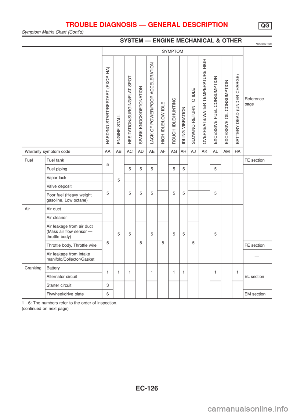
SYSTEM Ð ENGINE MECHANICAL & OTHERNJEC0041S03
SYMPTOM
Reference
page
HARD/NO START/RESTART (EXCP. HA)
ENGINE STALL
HESITATION/SURGING/FLAT SPOT
SPARK KNOCK/DETONATION
LACK OF POWER/POOR ACCELERATION
HIGH IDLE/LOW IDLE
ROUGH IDLE/HUNTING
IDLING VIBRATION
SLOW/NO RETURN TO IDLE
OVERHEATS/WATER TEMPERATURE HIGH
EXCESSIVE FUEL CONSUMPTION
EXCESSIVE OIL CONSUMPTION
BATTERY DEAD (UNDER CHARGE)
Warranty symptom code AA AB AC AD AE AF AG AH AJ AK AL AM HA
Fuel Fuel tank
5
5FE section
Fuel piping 5 5 5 5 5 5
Ð Vapor lock
Valve deposit
5 555 55 5
Poor fuel (Heavy weight
gasoline, Low octane)
Air Air duct
55555 5 Air cleaner
Air leakage from air duct
(Mass air flow sensor Ð
throttle body)
5555
Throttle body, Throttle wireFE section
Air leakage from intake
manifold/Collector/GasketÐ
Cranking Battery
111111 11
EL section Alternator circuit
Starter circuit 3
Flywheel/drive plate 6EM section
1 - 6: The numbers refer to the order of inspection.
(continued on next page)
TROUBLE DIAGNOSIS Ð GENERAL DESCRIPTIONQG
Symptom Matrix Chart (Cont'd)
EC-126
Page 569 of 2493

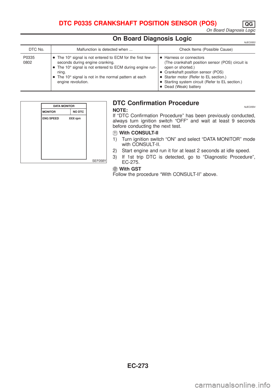
On Board Diagnosis LogicNJEC0553
DTC No. Malfunction is detected when ... Check Items (Possible Cause)
P0335
0802+The 10É signal is not entered to ECM for the first few
seconds during engine cranking.
+The 10É signal is not entered to ECM during engine run-
ning.
+The 10É signal is not in the normal pattern at each
engine revolution.+Harness or connectors
(The crankshaft position sensor (POS) circuit is
open or shorted.)
+Crankshaft position sensor (POS)
+Starter motor (Refer to EL section.)
+Starting system circuit (Refer to EL section.)
+Dead (Weak) battery
SEF058Y
DTC Confirmation ProcedureNJEC0554NOTE:
If ªDTC Confirmation Procedureº has been previously conducted,
always turn ignition switch ªOFFº and wait at least 9 seconds
before conducting the next test.
With CONSULT-II
1) Turn ignition switch ªONº and select ªDATA MONITORº mode
with CONSULT-II.
2) Start engine and run it for at least 2 seconds at idle speed.
3) If 1st trip DTC is detected, go to ªDiagnostic Procedureº,
EC-275.
With GST
Follow the procedure ªWith CONSULT-IIº above.
DTC P0335 CRANKSHAFT POSITION SENSOR (POS)QG
On Board Diagnosis Logic
EC-273
Page 575 of 2493

On Board Diagnosis LogicNJEC0222
DTC No. Malfunction is detected when ... Check Items (Possible Cause)
P0340
0340+The cylinder No. signal is not entered to ECM for the first
few seconds during engine cranking.
+The cylinder No. signal is not entered to ECM during
engine running.
+The cylinder No. signal is not in the normal pattern dur-
ing engine running.+Harness or connectors
(The camshaft position sensor (PHASE) circuit is
open or shorted.)
+Camshaft position sensor (PHASE)
+Starter motor (Refer to EL section.)
+Starting system circuit (Refer to EL section.)
DTC Confirmation ProcedureNJEC0223NOTE:
If ªDTC Confirmation Procedureº has been previously conducted,
always turn ignition switch ªOFFº and wait at least 9 seconds
before conducting the next test.
TESTING CONDITION:
Before performing the following procedure, confirm that bat-
tery voltage is more than 10.5V.
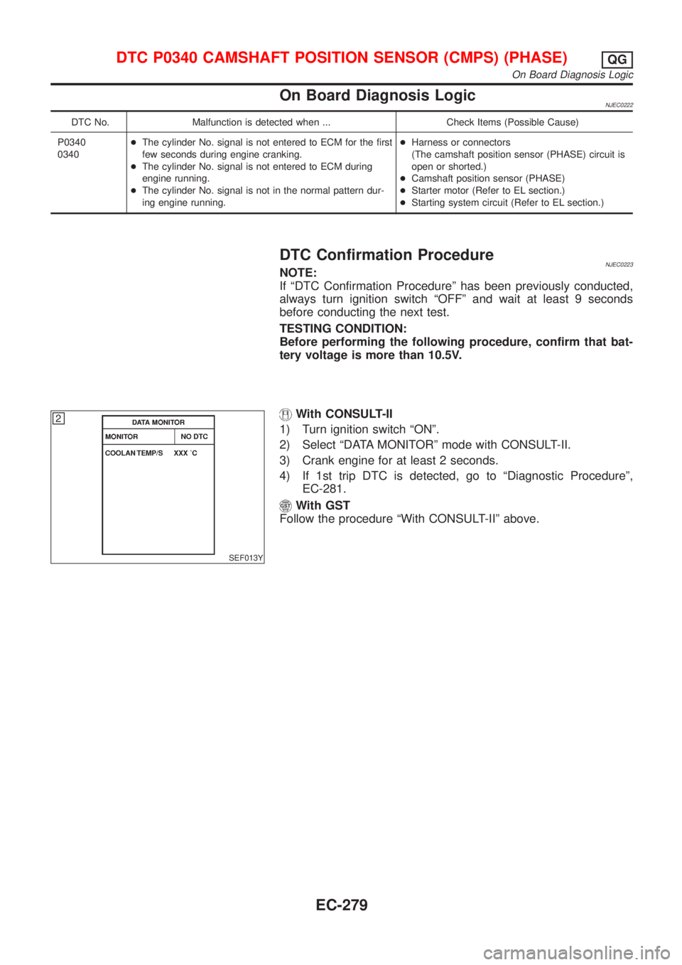
SEF013Y
With CONSULT-II
1) Turn ignition switch ªONº.
2) Select ªDATA MONITORº mode with CONSULT-II.
3) Crank engine for at least 2 seconds.
4) If 1st trip DTC is detected, go to ªDiagnostic Procedureº,
EC-281.
With GST
Follow the procedure ªWith CONSULT-IIº above.
DTC P0340 CAMSHAFT POSITION SENSOR (CMPS) (PHASE)QG
On Board Diagnosis Logic
EC-279
Page 577 of 2493
Diagnostic ProcedureNJEC0225
1 CHECK STARTING SYSTEM
Does the engine turn over?
(Does the starter motor operate?)
YesorNo
Ye s©GO TO 2.
No©Check starting system. (Refer to EL section.)
2 RETIGHTEN GROUND SCREWS
1. Turn ignition switch ªOFFº.
2. Loosen and retighten engine ground screws.
JEF104Y
©GO TO 3.
DTC P0340 CAMSHAFT POSITION SENSOR (CMPS) (PHASE)QG
Diagnostic Procedure
EC-281
Page 816 of 2493

Fuel Filter
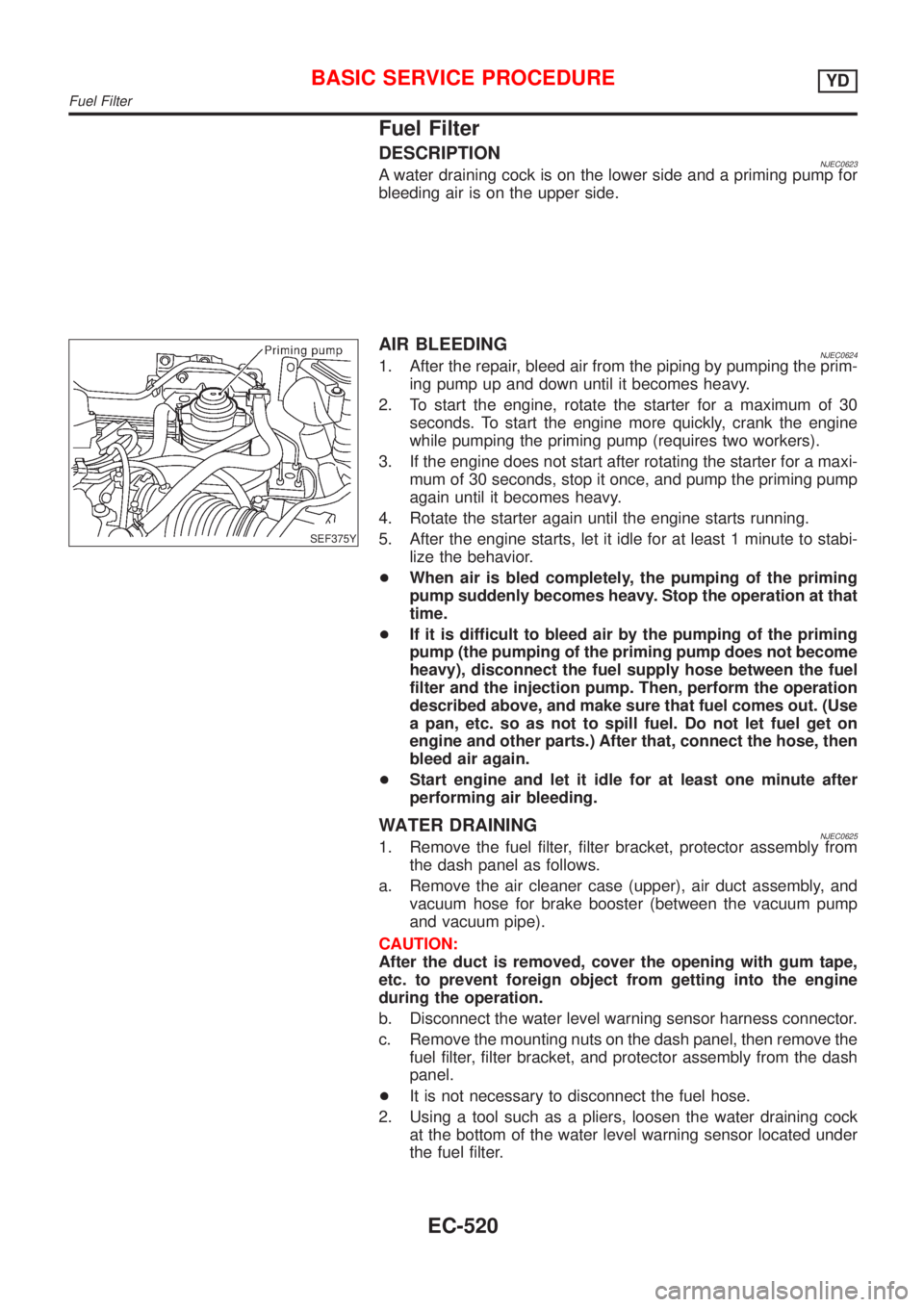
DESCRIPTIONNJEC0623A water draining cock is on the lower side and a priming pump for
bleeding air is on the upper side.
SEF375Y
AIR BLEEDINGNJEC06241. After the repair, bleed air from the piping by pumping the prim-
ing pump up and down until it becomes heavy.
2. To start the engine, rotate the starter for a maximum of 30
seconds. To start the engine more quickly, crank the engine
while pumping the priming pump (requires two workers).
3. If the engine does not start after rotating the starter for a maxi-
mum of 30 seconds, stop it once, and pump the priming pump
again until it becomes heavy.
4. Rotate the starter again until the engine starts running.
5. After the engine starts, let it idle for at least 1 minute to stabi-
lize the behavior.
+When air is bled completely, the pumping of the priming
pump suddenly becomes heavy. Stop the operation at that
time.
+If it is difficult to bleed air by the pumping of the priming
pump (the pumping of the priming pump does not become
heavy), disconnect the fuel supply hose between the fuel
filter and the injection pump. Then, perform the operation
described above, and make sure that fuel comes out. (Use
a pan, etc. so as not to spill fuel. Do not let fuel get on
engine and other parts.) After that, connect the hose, then
bleed air again.
+Start engine and let it idle for at least one minute after
performing air bleeding.
WATER DRAININGNJEC06251. Remove the fuel filter, filter bracket, protector assembly from
the dash panel as follows.
a. Remove the air cleaner case (upper), air duct assembly, and
vacuum hose for brake booster (between the vacuum pump
and vacuum pipe).
CAUTION:
After the duct is removed, cover the opening with gum tape,
etc. to prevent foreign object from getting into the engine
during the operation.
b. Disconnect the water level warning sensor harness connector.
c. Remove the mounting nuts on the dash panel, then remove the
fuel filter, filter bracket, and protector assembly from the dash
panel.
+It is not necessary to disconnect the fuel hose.
2. Using a tool such as a pliers, loosen the water draining cock
at the bottom of the water level warning sensor located under
the fuel filter.
BASIC SERVICE PROCEDUREYD
Fuel Filter
EC-520