2001 NISSAN ALMERA N16 battery location
[x] Cancel search: battery locationPage 7 of 2493

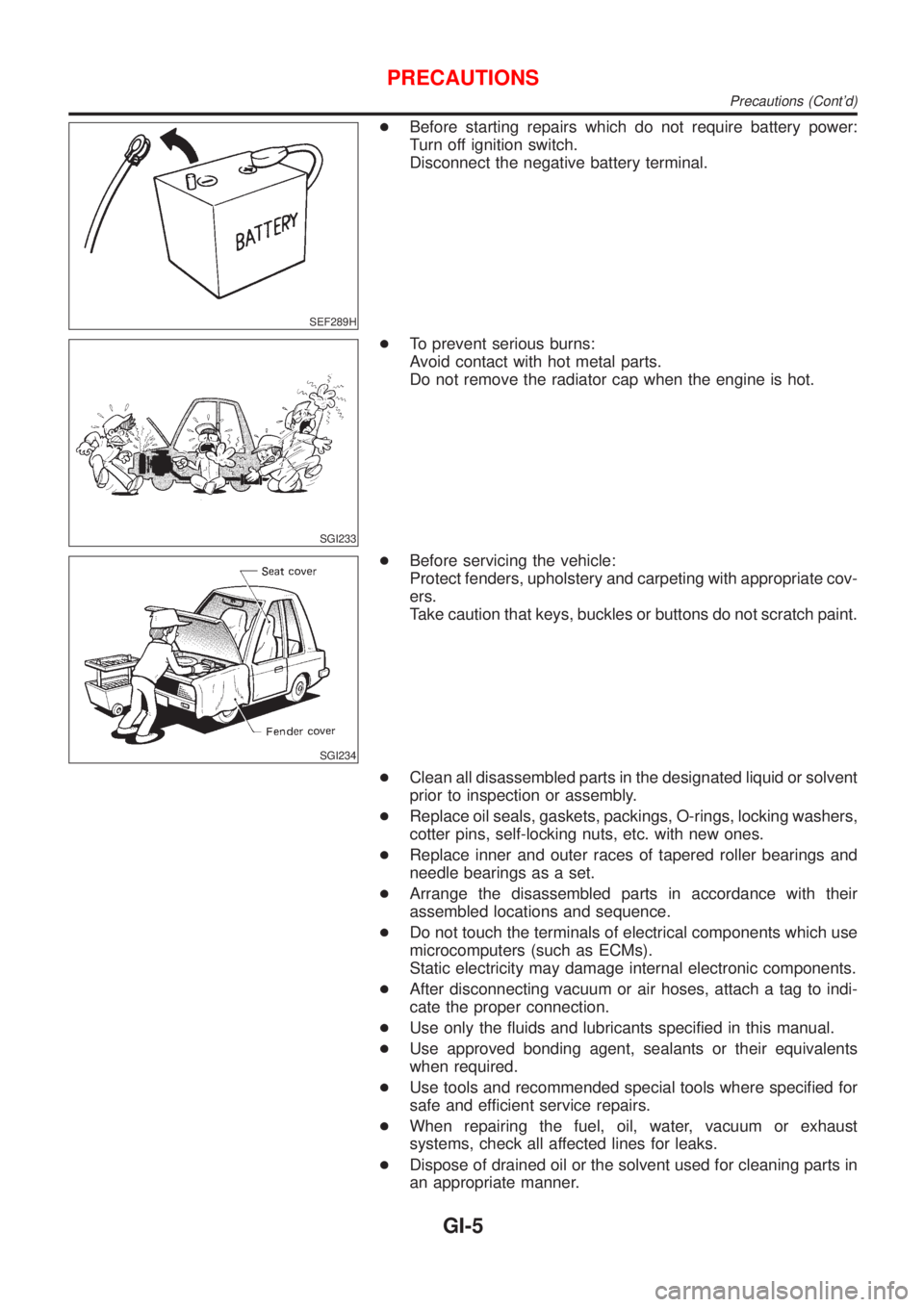
SEF289H
+Before starting repairs which do not require battery power:
Turn off ignition switch.
Disconnect the negative battery terminal.
SGI233
+To prevent serious burns:
Avoid contact with hot metal parts.
Do not remove the radiator cap when the engine is hot.
SGI234
+Before servicing the vehicle:
Protect fenders, upholstery and carpeting with appropriate cov-
ers.
Take caution that keys, buckles or buttons do not scratch paint.
+Clean all disassembled parts in the designated liquid or solvent
prior to inspection or assembly.
+Replace oil seals, gaskets, packings, O-rings, locking washers,
cotter pins, self-locking nuts, etc. with new ones.
+Replace inner and outer races of tapered roller bearings and
needle bearings as a set.
+Arrange the disassembled parts in accordance with their
assembled locations and sequence.
+Do not touch the terminals of electrical components which use
microcomputers (such as ECMs).
Static electricity may damage internal electronic components.
+After disconnecting vacuum or air hoses, attach a tag to indi-
cate the proper connection.
+Use only the fluids and lubricants specified in this manual.
+Use approved bonding agent, sealants or their equivalents
when required.
+Use tools and recommended special tools where specified for
safe and efficient service repairs.
+When repairing the fuel, oil, water, vacuum or exhaust
systems, check all affected lines for leaks.
+Dispose of drained oil or the solvent used for cleaning parts in
an appropriate manner.
PRECAUTIONS
Precautions (Cont'd)
GI-5
Page 16 of 2493

Description=NJGI0003S02
Number Item Description
1 Power condition+This shows the condition when the system receives battery positive voltage (can be
operated).
2 Fusible link+The double line shows that this is a fusible link.
+The open circle shows current flow in, and the shaded circle shows current flow out.
3Fusible link/fuse loca-
tion+This shows the location of the fusible link or fuse in the fusible link or fuse box. For
arrangement, refer to EL-10, ªPOWER SUPPLY ROUTINGº.
4 Fuse+The single line shows that this is a fuse.
+The open circle shows current flow in, and the shaded circle shows current flow out.
5 Current rating+This shows the current rating of the fusible link or fuse.
6 Connectors+This shows that connector E3 is female and connector M1 is male.
+The G/R wire is located in the 1A terminal of both connectors.
+Terminal number with an alphabet (1A, 5B, etc.) indicates that the connector is SMJ con-
nector. Refer to GI-19.
7 Optional splice+The open circle shows that the splice is optional depending on vehicle application.
8 Splice+The shaded circle shows that the splice is always on the vehicle.
9 Page crossing+This arrow shows that the circuit continues to an adjacent page.
+The A will match with the A on the preceding or next page.
10 Common connector+The dotted lines between terminals show that these terminals are part of the same con-
nector.
11 Option abbreviation+This shows that the circuit is optional depending on vehicle application.
12 Relay+This shows an internal representation of the relay. For details, refer to EL-7, ªSTAN-
DARDIZED RELAYº.
13 Connectors+This shows that the connector is connected to the body or a terminal with bolt or nut.
14 Wire color+This shows a code for the color of the wire.
B = Black
W = White
R = Red
G = Green
L = Blue
Y = Yellow
LG = Light GreenBR = Brown
OR = Orange
P = Pink
PU = Purple
GY = Gray
SB = Sky Blue
CH = Dark Brown
DG = Dark Green
When the wire color is striped, the base color is given first, followed by the stripe color as
shown below:
Example: L/W = Blue with White Stripe
15 Option description+This shows a description of the option abbreviation used on the page.
16 Switch+This shows that continuity exists between terminals 1 and 2 when the switch is in the A
position. Continuity exists between terminals 1 and 3 when the switch is in the B posi-
tion.
17 Assembly parts+Connector terminal in component shows that it is a harness incorporated assembly.
18 Cell code+This identifies each page of the wiring diagram by section, system and wiring diagram
page number.
19 Current flow arrow+Arrow indicates electric current flow, especially where the direction of standard flow (ver-
tically downward or horizontally from left to right) is difficult to follow.
+A double arrow ª
º shows that current can flow in either direction depending on cir-
cuit operation.
HOW TO READ WIRING DIAGRAMS
Description
GI-14
Page 33 of 2493

NJGI0006
NOTICE:
Trouble diagnoses indicate work procedures required to diagnose
problems effectively. Observe the following instructions before
diagnosing.
1)Before performing trouble diagnoses, read the ªPrelimi-
nary Checkº, the ªSymptom Chartº or the ªWork Flowº.
2)After repairs, re-check that the problem has been com-
pletely eliminated.
3)Refer to Component Parts and Harness Connector Loca-
tion for the Systems described in each section for
identification/location of components and harness con-
nectors.
4)Refer to the Circuit Diagram for quick pinpoint check.
If you need to check circuit continuity between harness
connectors in more detail, such as when a sub-harness is
used, refer to Wiring Diagram in each individual section
and Harness Layout in EL section for identification of har-
ness connectors.
5)When checking circuit continuity, ignition switch should
be OFF.
6)Before checking voltage at connectors, check battery volt-
age.
7)After accomplishing the Diagnostic Procedures and Elec-
trical Components Inspection, make sure that all harness
connectors are reconnected as they were.
HOW TO FOLLOW TROUBLE DIAGNOSES
GI-31
Page 444 of 2493

5 CHECK POWER SUPPLY-II
1. Disconnect ECM relay. (For ECM relay location, refer to ªEngine Control Compartment Parts Locationº.)
2. Check voltage between ECM relay terminals 1, 6 and ground with CONSULT-II or tester.
SEF101Y
OK or NG
OK©GO TO 7.
NG©GO TO 6.
6 DETECT MALFUNCTIONING PART
Check the following.
+15A fuse and 10A fuse
+Harness for open or short between ECM relay and battery
©Repair open circuit or short to ground or short to power in harness or connectors.
7 CHECK OUTPUT SIGNAL CIRCUIT FOR OPEN AND SHORT
1. Check harness continuity between ECM terminal 31 and ECM relay terminal 2.
Continuity should exist.
2. Also check harness for short to ground and short to power.
OK or NG
OK©Go to ªIGNITION SIGNALº, EC-451.
NG©GO TO 8.
8 DETECT MALFUNCTIONING PART
Check the harness for open or short between ECM relay and ECM.
©Repair open circuit or short to ground or short to power in harness or connectors.
TROUBLE DIAGNOSIS FOR POWER SUPPLYQG
Main Power Supply and Ground Circuit (Cont'd)
EC-148
Page 859 of 2493

5 CHECK ECM POWER SUPPLY CIRCUIT-II
1. Reconnect ECM harness connector.
2. Turn ignition switch ªONº and then ªOFFº.
3. Check voltage between ECM terminals 107, 108, 109 and ground with CONSULT-II or tester.
SEF896Y
OK or NG
OK©Check electronic control fuel injection pump power supply circuit. Refer to ªDiagnostic
Procedureº, EC-662.
NG (Battery voltage
does not exist.)©GO TO 6.
NG (Battery voltage
exists for more than a
few seconds.)©GO TO 10.
6 CHECK ECM POWER SUPPLY CIRCUIT-III
1. Disconnect ECM relay. (For ECM relay location, refer to ªEngine Control Component Parts Locationº.)
2. Check voltage between relay terminals 1, 6 and ground with CONSULT-II or tester.
SEF399Y
OK or NG
OK©GO TO 8.
NG©GO TO 7.
7 DETECT MALFUNCTIONING PART
Check the following.
+20A fuse
+10A fuse
+Harness for open or short between ECM relay and battery
©Repair open circuit or short to ground or short to power in harness or connectors.
TROUBLE DIAGNOSIS FOR POWER SUPPLYYD
Main Power Supply and Ground Circuit (Cont'd)
EC-563
Page 964 of 2493

Diagnostic ProcedureNJEC0748
1 CHECK ECM POWER SUPPLY CIRCUIT
1. Turn ignition switch ªOFFº.
2. Disconnect ECM relay. (For ECM relay location, refer to ªEngine Control Component Parts Locationº.)
3. Check voltage between ECM terminals 1, 6 and ground with CONSULT-II or tester.
SEF399Y
OK or NG
OK©GO TO 3.
NG©GO TO 2.
2 DETECT MALFUNCTIONING PART
Check the following.
1. 20A fuse
2. 10A fuse
3. Harness for open and short between ECM relay and battery
©Repair open circuit or short to ground or short to power in harness or connectors.
3 CHECK ECM INPUT SIGNAL CIRCUIT FOR OPEN AND SHORT
1. Turn ignition switch ªOFFº.
2. Disconnect ECM harness connector.
3. Check harness continuity between ECM terminals 107, 108, 109 and ECM relay terminal 7. Refer to Wiring Diagram.
Continuity should exist.
4. Also check harness for short to ground and short to power.
OK or NG
OK©GO TO 5.
NG©GO TO 4.
4 DETECT MALFUNCTIONING PART
Check the following.
1. Harness connectors E75, F36
2. Harness for open and short between ECM and ECM relay
©Repair open circuit or short to ground or short to power in harness or connectors.
5 CHECK ECM OUTPUT SIGNAL CIRCUIT FOR OPEN AND SHORT
1. Check harness continuity between ECM terminal 325 and ECM relay terminal 2. Refer to Wiring Diagram.
Continuity should exist.
2. Also check harness for short to ground and short to power.
OK or NG
OK©GO TO 7.
NG©GO TO 6.
DTC P1620 ECM RLYYD
Diagnostic Procedure
EC-668
Page 986 of 2493

3 CHECK EGR VOLUME CONTROL VALVE POWER SUPPLY CIRCUIT-II
1. Turn ignition switch ªOFFº.
2. Disconnect ECM relay. (For ECM relay location, refer to ªEngine Control Component Parts Locationº.)
3. Check harness continuity between ECM relay terminal 5 and EGR volume control valve terminals 2 and 5. Refer to
Wiring Diagram.
Continuity should exist.
OK or NG
OK©GO TO 4.
NG©Repair open circuit or short to ground or short to power in harness or connectors.
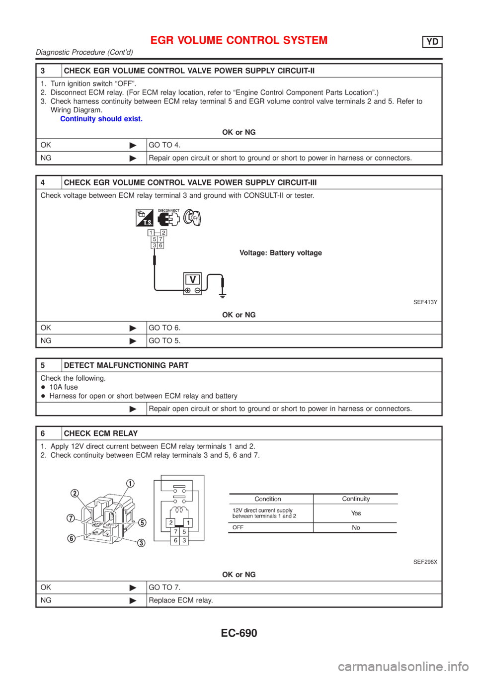
4 CHECK EGR VOLUME CONTROL VALVE POWER SUPPLY CIRCUIT-III
Check voltage between ECM relay terminal 3 and ground with CONSULT-II or tester.
SEF413Y
OK or NG
OK©GO TO 6.
NG©GO TO 5.
5 DETECT MALFUNCTIONING PART
Check the following.
+10A fuse
+Harness for open or short between ECM relay and battery
©Repair open circuit or short to ground or short to power in harness or connectors.
6 CHECK ECM RELAY
1. Apply 12V direct current between ECM relay terminals 1 and 2.
2. Check continuity between ECM relay terminals 3 and 5, 6 and 7.
SEF296X
OK or NG
OK©GO TO 7.
NG©Replace ECM relay.
EGR VOLUME CONTROL SYSTEMYD
Diagnostic Procedure (Cont'd)
EC-690
Page 2114 of 2493

WARNING CHIME....................................................... 113
Component Parts and Harness Connector
Location ................................................................... 113
System Description .................................................. 113
Wiring Diagram - CHIME - ...................................... 115
Trouble Diagnoses................................................... 117
FRONT WIPER AND WASHER..................................123
System Description ..................................................123
Wiring Diagram - WIPER - ......................................125
Removal and Installation .........................................127
Washer Nozzle Adjustment .....................................128
Washer Tube Layout ...............................................128
REAR WIPER AND WASHER....................................129
Wiring Diagram - WIP/R -........................................129
Removal and Installation .........................................131
Washer Nozzle Adjustment .....................................131
Washer Tube Layout ...............................................132
HEADLAMP WASHER................................................133
Wiring Diagram - HLC - ...........................................133
Washer Tube Layout ...............................................134
HORN...........................................................................135
Wiring Diagram - HORN - .......................................135
CIGARETTE LIGHTER................................................136
Wiring Diagram - CIGAR -.......................................136
CLOCK.........................................................................137
Wiring Diagram - CLOCK -......................................137
REAR WINDOW DEFOGGER.....................................138
System Description ..................................................138
Schematic ................................................................139
Wiring Diagram - DEF - ...........................................140
Trouble Diagnoses...................................................143
Electrical Components Inspection ...........................146
Filament Check ........................................................147
Filament Repair .......................................................148
AUDIO..........................................................................149
System Description ..................................................149
Schematic ................................................................151
Wiring Diagram - AUDIO - .......................................152
Trouble Diagnoses...................................................160
Inspection.................................................................161
AUDIO ANTENNA.......................................................162
Location of Antenna .................................................162
Antenna Rod Replacement .....................................162
HEATED SEAT............................................................163
Wiring Diagram - H/SEAT - .....................................163
POWER SUNROOF.....................................................165
Wiring Diagram - SROOF - .....................................165
Trouble Diagnoses...................................................166
DOOR MIRROR...........................................................167
Wiring Diagram - MIRROR - ...................................167
POWER WINDOW.......................................................169
System Description ..................................................169Schematic ................................................................171
Wiring Diagram - WINDOW - ..................................172
Trouble Diagnoses...................................................176
POWER DOOR LOCK.................................................177
System Description ..................................................177
Schematic ................................................................178
Wiring Diagram - D/LOCK -.....................................180
Trouble Diagnoses...................................................187
POWER DOOR LOCK - SUPER LOCK -...................196
System Description ..................................................196
Schematic ................................................................198
Wiring Diagram - S/LOCK - .....................................200
Trouble Diagnoses...................................................207
MULTI-REMOTE CONTROL SYSTEM.......................220
System Description ..................................................220
Wiring Diagram - MULTI - .......................................221
Trouble Diagnoses...................................................223
ID Code Entry Procedure ........................................227
Remote Controller Battery Replacement.................228
TIME CONTROL UNIT................................................229
Description ...............................................................229
Trouble Diagnoses...................................................230
Schematic ................................................................232
NATS (NISSAN ANTI-THEFT SYSTEM).....................234
Component Parts and Harness Connetor
Location ...................................................................234
System Description ..................................................234
System Composition ................................................236
Wiring Diagram - NATS -.........................................237
CONSULT-II .............................................................238
Trouble Diagnoses...................................................241
How to Replace NATS IMMU ..................................258
NAVIGATION SYSTEM...............................................259
Precautions ..............................................................259
Component Parts Location ......................................260
System Description ..................................................261
Schematic ................................................................269
Wiring Diagram - NAVI - ..........................................270
Self-diagnosis Mode ................................................278
Confirmation/Adjustment Mode ...............................281
Control Panel Mode .................................................293
Guide Volume Setting ..............................................300
Anti-theft System .....................................................301
CONSULT-II .............................................................302
Trouble Diagnoses...................................................303
This Condition Is Not Abnormal...............................309
Program Loading .....................................................318
ELECTRICAL UNITS LOCATION...............................319
Engine Compartment ...............................................319
Passenger Compartment/LHD Models ....................320
Passenger Compartment/RHD Models ...................322
CONTENTS(Cont'd)
EL-2