2001 NISSAN ALMERA N16 coil diagram
[x] Cancel search: coil diagramPage 302 of 2493
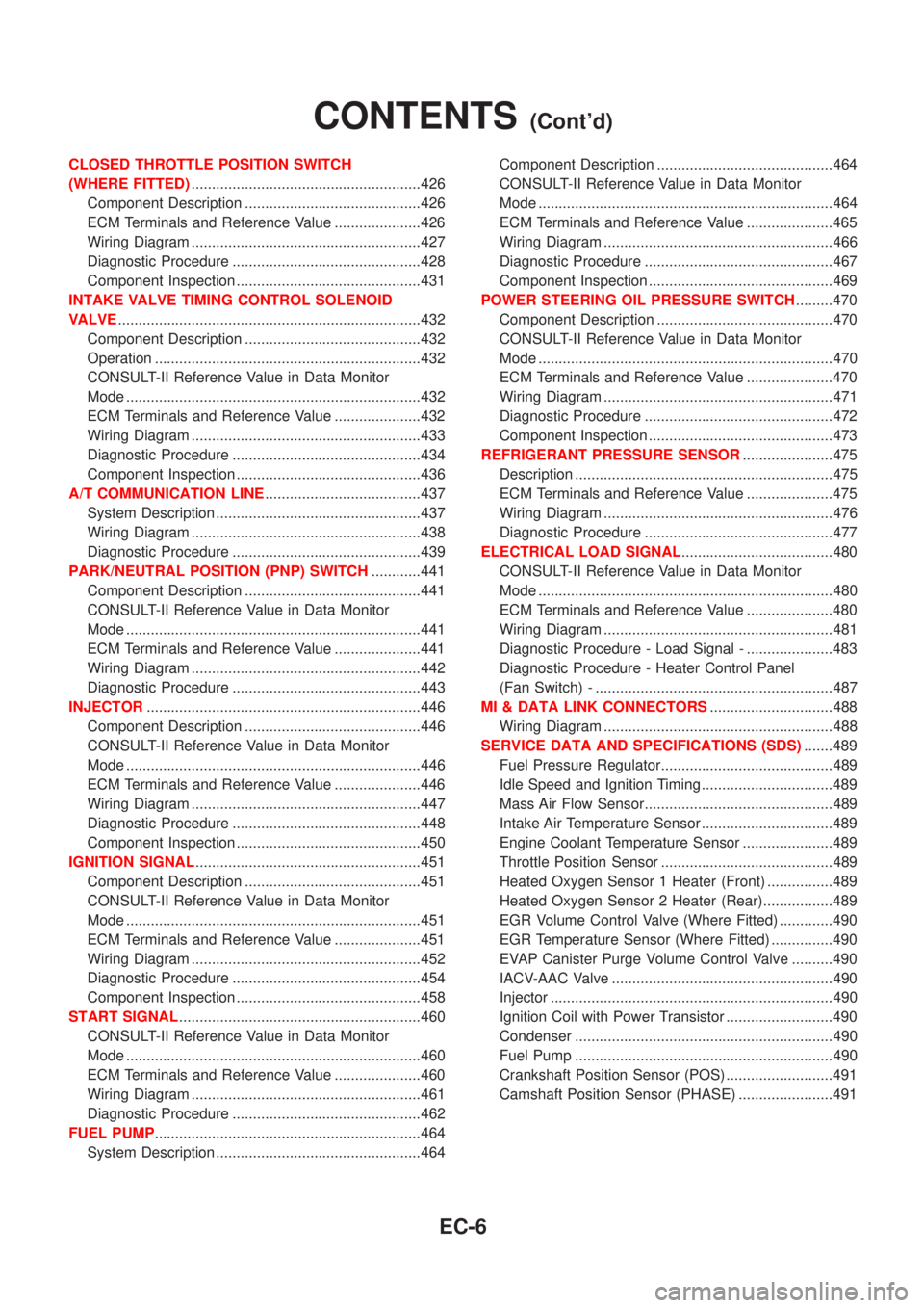
CLOSED THROTTLE POSITION SWITCH
(WHERE FITTED)........................................................426
Component Description ...........................................426
ECM Terminals and Reference Value .....................426
Wiring Diagram ........................................................427
Diagnostic Procedure ..............................................428
Component Inspection .............................................431
INTAKE VALVE TIMING CONTROL SOLENOID
VALVE..........................................................................432
Component Description ...........................................432
Operation .................................................................432
CONSULT-II Reference Value in Data Monitor
Mode ........................................................................432
ECM Terminals and Reference Value .....................432
Wiring Diagram ........................................................433
Diagnostic Procedure ..............................................434
Component Inspection .............................................436
A/T COMMUNICATION LINE......................................437
System Description ..................................................437
Wiring Diagram ........................................................438
Diagnostic Procedure ..............................................439
PARK/NEUTRAL POSITION (PNP) SWITCH............441
Component Description ...........................................441
CONSULT-II Reference Value in Data Monitor
Mode ........................................................................441
ECM Terminals and Reference Value .....................441
Wiring Diagram ........................................................442
Diagnostic Procedure ..............................................443
INJECTOR...................................................................446
Component Description ...........................................446
CONSULT-II Reference Value in Data Monitor
Mode ........................................................................446
ECM Terminals and Reference Value .....................446
Wiring Diagram ........................................................447
Diagnostic Procedure ..............................................448
Component Inspection .............................................450
IGNITION SIGNAL.......................................................451
Component Description ...........................................451
CONSULT-II Reference Value in Data Monitor
Mode ........................................................................451
ECM Terminals and Reference Value .....................451
Wiring Diagram ........................................................452
Diagnostic Procedure ..............................................454
Component Inspection .............................................458
START SIGNAL...........................................................460
CONSULT-II Reference Value in Data Monitor
Mode ........................................................................460
ECM Terminals and Reference Value .....................460
Wiring Diagram ........................................................461
Diagnostic Procedure ..............................................462
FUEL PUMP.................................................................464
System Description ..................................................464Component Description ...........................................464
CONSULT-II Reference Value in Data Monitor
Mode ........................................................................464
ECM Terminals and Reference Value .....................465
Wiring Diagram ........................................................466
Diagnostic Procedure ..............................................467
Component Inspection .............................................469
POWER STEERING OIL PRESSURE SWITCH.........470
Component Description ...........................................470
CONSULT-II Reference Value in Data Monitor
Mode ........................................................................470
ECM Terminals and Reference Value .....................470
Wiring Diagram ........................................................471
Diagnostic Procedure ..............................................472
Component Inspection .............................................473
REFRIGERANT PRESSURE SENSOR......................475
Description ...............................................................475
ECM Terminals and Reference Value .....................475
Wiring Diagram ........................................................476
Diagnostic Procedure ..............................................477
ELECTRICAL LOAD SIGNAL.....................................480
CONSULT-II Reference Value in Data Monitor
Mode ........................................................................480
ECM Terminals and Reference Value .....................480
Wiring Diagram ........................................................481
Diagnostic Procedure - Load Signal - .....................483
Diagnostic Procedure - Heater Control Panel
(Fan Switch) - ..........................................................487
MI & DATA LINK CONNECTORS..............................488
Wiring Diagram ........................................................488
SERVICE DATA AND SPECIFICATIONS (SDS).......489
Fuel Pressure Regulator..........................................489
Idle Speed and Ignition Timing ................................489
Mass Air Flow Sensor..............................................489
Intake Air Temperature Sensor ................................489
Engine Coolant Temperature Sensor ......................489
Throttle Position Sensor ..........................................489
Heated Oxygen Sensor 1 Heater (Front) ................489
Heated Oxygen Sensor 2 Heater (Rear).................489
EGR Volume Control Valve (Where Fitted) .............490
EGR Temperature Sensor (Where Fitted) ...............490
EVAP Canister Purge Volume Control Valve ..........490
IACV-AAC Valve ......................................................490
Injector .....................................................................490
Ignition Coil with Power Transistor ..........................490
Condenser ...............................................................490
Fuel Pump ...............................................................490
Crankshaft Position Sensor (POS) ..........................491
Camshaft Position Sensor (PHASE) .......................491
CONTENTS(Cont'd)
EC-6
Page 598 of 2493

5 CHECK INJECTORS
1. Refer to Wiring Diagram for Injectors, EC-447.
2. Stop engine and then turn ignition switch ªONº.
3. Check voltage between ECM terminals 101, 103, 105 and 107 and ground with CONSULT-II or tester.
SEF075X
Battery voltage should exist.
OK or NG
OK©GO TO 6.
NG©Perform ªDiagnostic Procedureº INJECTOR, EC-448.
6 CHECK IGNITION SPARK
1. Disconnect ignition coil assembly from rocker cover.
2. Connect a known good spark plug to the ignition coil assembly.
3. Place end of spark plug against a suitable ground and crank engine.
4. Check for spark.
SEF575Q
OK or NG
OK©GO TO 7.
NG©Check ignition coil, power transistor and their circuits. Refer to EC-451.
7 CHECK INJECTOR
1. Turn ignition switch ªOFFº.
2. Remove injector assembly. Refer to EC-39.
Keep fuel hose and all injectors connected to injector gallery.
3. Disconnect camshaft position sensor harness connector.
4. Turn ignition switch ªONº.
Make sure fuel does not drip from injector.
OK or NG
OK (Does not drip)©GO TO 8.
NG (Drips)©Replace the injector(s) from which fuel is dripping.
DTC P0420 THREE WAY CATALYST FUNCTIONQG
Diagnostic Procedure (Cont'd)
EC-302
Page 751 of 2493
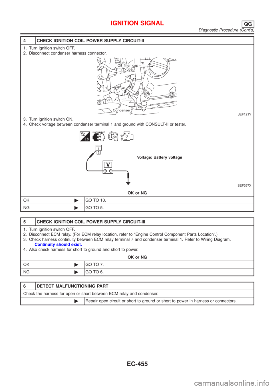
4 CHECK IGNITION COIL POWER SUPPLY CIRCUIT-II
1. Turn ignition switch OFF.
2. Disconnect condenser harness connector.
JEF121Y
3. Turn ignition switch ON.
4. Check voltage between condenser terminal 1 and ground with CONSULT-II or tester.
SEF367X
OK or NG
OK©GO TO 10.
NG©GO TO 5.
5 CHECK IGNITION COIL POWER SUPPLY CIRCUIT-III
1. Turn ignition switch OFF.
2. Disconnect ECM relay. (For ECM relay location, refer to ªEngine Control Component Parts Locationº.)
3. Check harness continuity between ECM relay terminal 7 and condenser terminal 1. Refer to Wiring Diagram.
Continuity should exist.
4. Also check harness for short to ground and short to power.
OK or NG
OK©GO TO 7.
NG©GO TO 6.
6 DETECT MALFUNCTIONING PART
Check the harness for open or short between ECM relay and condenser.
©Repair open circuit or short to ground or short to power in harness or connectors.
IGNITION SIGNALQG
Diagnostic Procedure (Cont'd)
EC-455
Page 752 of 2493
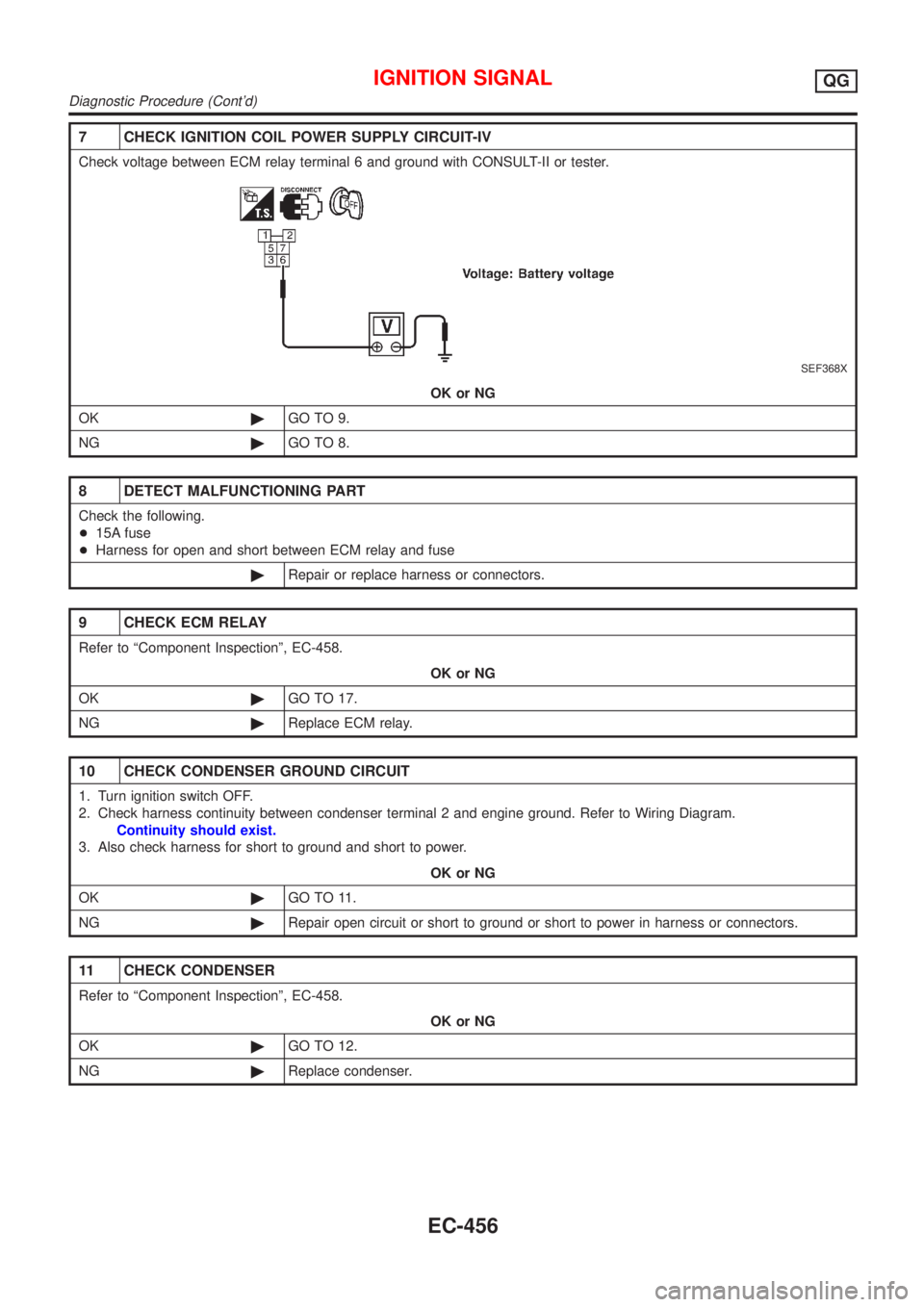
7 CHECK IGNITION COIL POWER SUPPLY CIRCUIT-IV
Check voltage between ECM relay terminal 6 and ground with CONSULT-II or tester.
SEF368X
OK or NG
OK©GO TO 9.
NG©GO TO 8.
8 DETECT MALFUNCTIONING PART
Check the following.
+15A fuse
+Harness for open and short between ECM relay and fuse
©Repair or replace harness or connectors.
9 CHECK ECM RELAY
Refer to ªComponent Inspectionº, EC-458.
OK or NG
OK©GO TO 17.
NG©Replace ECM relay.
10 CHECK CONDENSER GROUND CIRCUIT
1. Turn ignition switch OFF.
2. Check harness continuity between condenser terminal 2 and engine ground. Refer to Wiring Diagram.
Continuity should exist.
3. Also check harness for short to ground and short to power.
OK or NG
OK©GO TO 11.
NG©Repair open circuit or short to ground or short to power in harness or connectors.
11 CHECK CONDENSER
Refer to ªComponent Inspectionº, EC-458.
OK or NG
OK©GO TO 12.
NG©Replace condenser.
IGNITION SIGNALQG
Diagnostic Procedure (Cont'd)
EC-456
Page 753 of 2493
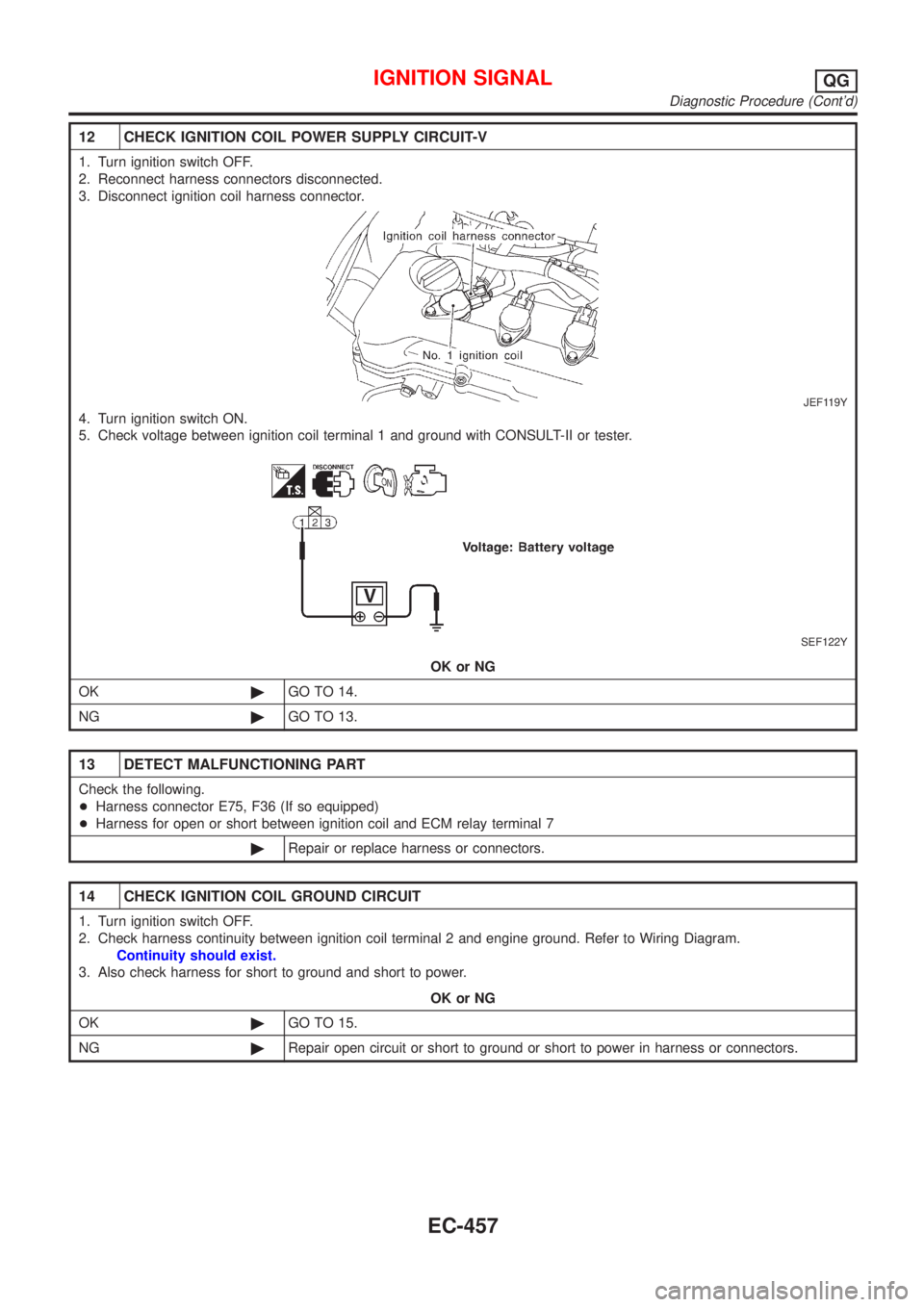
12 CHECK IGNITION COIL POWER SUPPLY CIRCUIT-V
1. Turn ignition switch OFF.
2. Reconnect harness connectors disconnected.
3. Disconnect ignition coil harness connector.
JEF119Y
4. Turn ignition switch ON.
5. Check voltage between ignition coil terminal 1 and ground with CONSULT-II or tester.
SEF122Y
OK or NG
OK©GO TO 14.
NG©GO TO 13.
13 DETECT MALFUNCTIONING PART
Check the following.
+Harness connector E75, F36 (If so equipped)
+Harness for open or short between ignition coil and ECM relay terminal 7
©Repair or replace harness or connectors.
14 CHECK IGNITION COIL GROUND CIRCUIT
1. Turn ignition switch OFF.
2. Check harness continuity between ignition coil terminal 2 and engine ground. Refer to Wiring Diagram.
Continuity should exist.
3. Also check harness for short to ground and short to power.
OK or NG
OK©GO TO 15.
NG©Repair open circuit or short to ground or short to power in harness or connectors.
IGNITION SIGNALQG
Diagnostic Procedure (Cont'd)
EC-457
Page 754 of 2493

15 CHECK IGNITION COIL OUTPUT SIGNAL CIRCUIT
1. Disconnect ECM harness connector.
2. Check harness continuity between ECM terminals 35, 36, 37, 38 and ignition coil terminal 3. Refer to Wiring Diagram.
Continuity should exist.
3. Also check harness for short to ground and short to power.
OK or NG
OK©GO TO 16.
NG©Repair open circuit or short to ground or short to power in harness or connectors.
16 CHECK IGNITION COIL WITH POWER TRANSISTOR
Refer to ªComponent Inspectionº, EC-458.
OK or NG
OK©GO TO 17.
NG©Replace ignition coil with power transistor.
17 CHECK INTERMITTENT INCIDENT
Refer to ªTROUBLE DIAGNOSIS FOR INTERMITTENT INCIDENTº, EC-144.
©INSPECTION END
SEF371Q
Component InspectionNJEC0547IGNITION COIL WITH POWER TRANSISTORNJEC0547S011. Disconnect ignition coil with power transistor harness connec-
tor.
2. Check ignition coil with power transistor for resistance as show
in the figure.
Terminal No. (Polarity) ResistanceW[at 25ÉC (77ÉF)]
3 (+) - 2 (þ) Except 0 or¥
1 (+) - 3 (þ)
Except 0
1 (+) - 2 (þ)
If NG, replace ignition coil with power transistor assembly.
SEF123Y
ECM RELAYNJEC0547S031. Apply 12V of direct current between ECM relay terminals 1 and
2.
2. Check continuity between ECM relay terminals 3 and 5, and 6
and 7.
Condition Continuity
12V direct current supply between ter-
minals 1 and 2Ye s
OFF No
IGNITION SIGNALQG
Diagnostic Procedure (Cont'd)
EC-458
Page 2035 of 2493
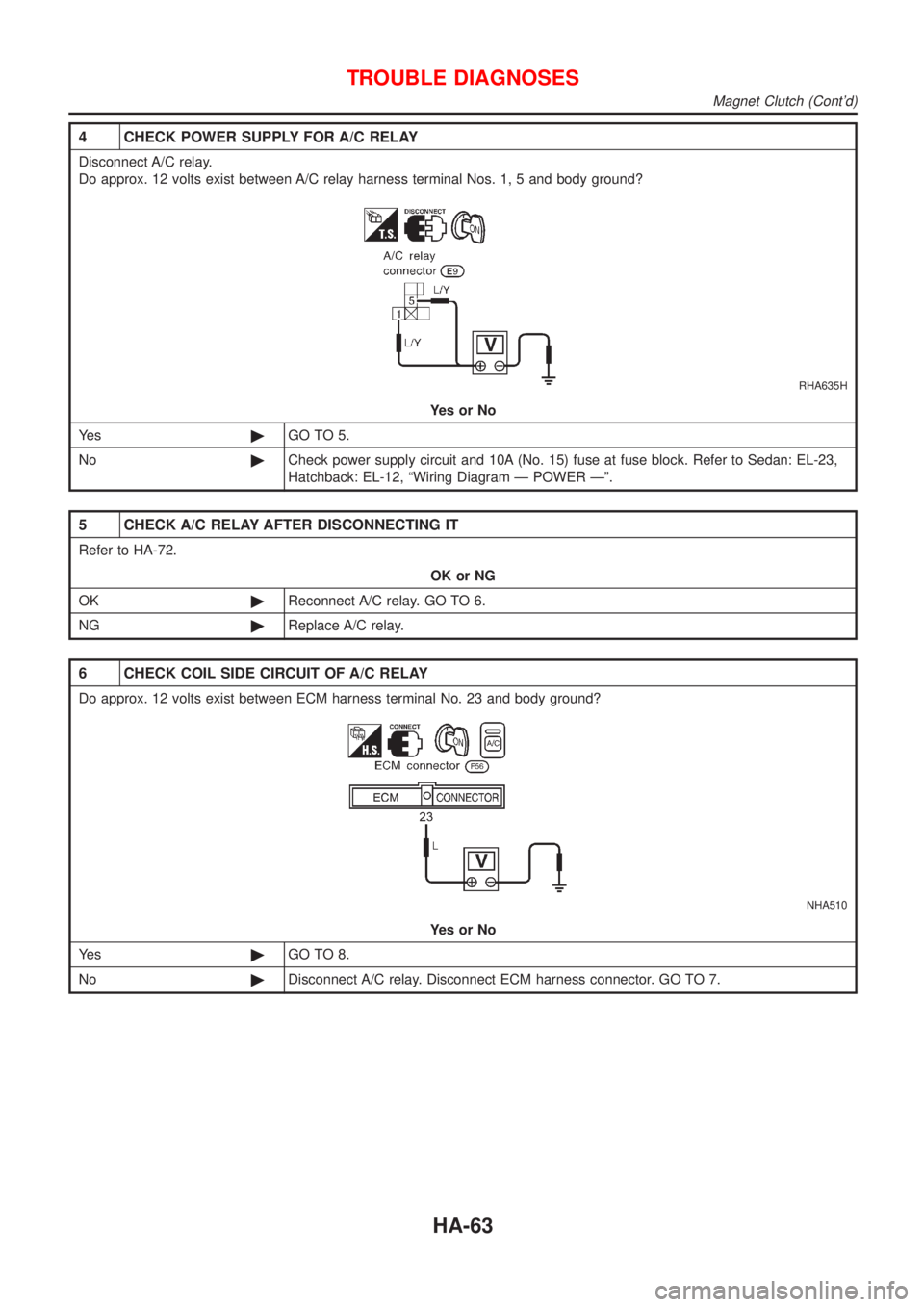
4 CHECK POWER SUPPLY FOR A/C RELAY
Disconnect A/C relay.
Do approx. 12 volts exist between A/C relay harness terminal Nos. 1, 5 and body ground?
RHA635H
YesorNo
Ye s©GO TO 5.
No©Check power supply circuit and 10A (No. 15) fuse at fuse block. Refer to Sedan: EL-23,
Hatchback: EL-12, ªWiring Diagram Ð POWER к.
5 CHECK A/C RELAY AFTER DISCONNECTING IT
Refer to HA-72.
OK or NG
OK©Reconnect A/C relay. GO TO 6.
NG©Replace A/C relay.
6 CHECK COIL SIDE CIRCUIT OF A/C RELAY
Do approx. 12 volts exist between ECM harness terminal No. 23 and body ground?
NHA510
YesorNo
Ye s©GO TO 8.
No©Disconnect A/C relay. Disconnect ECM harness connector. GO TO 7.
TROUBLE DIAGNOSES
Magnet Clutch (Cont'd)
HA-63
Page 2483 of 2493
CONSULT for ABS .................................... BR-58
CONSULT for engine ........................ EC-81, 527
COOL/F - Wiring diagram ............... EC-337, 618
Camshaft inspection ......................... EM-36, 122
Camshaft position sensor (CMPS) ......... EC-278
Camshaft position sensor (PHASE) ........ EC-278
Canister - See EVAP canister ................... EC-33
Charging system ....................................... SC-24
Cigarette lighter ....................................... EL-136
Circuit breaker ........................................... EL-22
Closed throttle position switch ....... EC-321, 426
Clutch cover .............................................. CL-22
Clutch disc ................................................. CL-22
Clutch master cylinder ............................... CL-11
Clutch operating cylinder ........................... CL-14
Clutch pedal .............................................. CL-10
Clutch release bearing ........................ CL-17, 20
Clutch release mechanism .................. CL-17, 20
Clutch withdrawal lever ....................... CL-17, 20
Coil spring (front) ........................................ SU-9
Coil spring (rear) ....................................... SU-21
Collision diagnosis .................................... RS-71
Combination lamp, rear, removal and
installation .............................................. BT-47
Combination meter removal and instal-
lation - See Instrument panel ................ BT-25
Combination meter .................................... EL-89
Combination switch ................................... EL-37
Compression pressure ............................. EM-82
Compressor clutch removal and
installation .............................................. HA-89
Compressor precaution ............................... HA-5
Compressor special service tool ................. HA-9
Connecting rod bearing clearance ... EM-58, 150
Connecting rod bushing clearance ... EM-59, 152
Connecting rod ................................. EM-55, 145
Console box - See Instrument panel ......... BT-25
Control lever (M/T) .................................... MT-29
Control valve (A/T) ................................... AT-375
Converter housing installation ................. AT-347
Coolant mixture ratio ................................ MA-22
Cooling circuit (engine) ....................... LC-12, 36
Cooling fan control system .................. LC-17, 42
Cooling fan control .......................... EC-334, 618
Cooling fan motor ................................... EC-346
Cooling fan relay ..................................... EC-345
Coupling sleeve (M/T) .................. MT-31, 55, 93
Crankcase emission control system -
See Positive crankcase ventilation ...... EC-37,
508
Crankcase ventilation system - See
Positive crankcase ventilation ....... EC-37, 508
Crankshaft position sensor (OBD) .. EC-272, 394
Crankshaft position sensor (POS) .. EC-272, 394
Crankshaft position sensor (TDC) .......... EC-587
Crankshaft ........................................ EM-57, 148
Cylinder block ................................... EM-52, 139
Cylinder head .................................... EM-33, 118D
DEF - Wiring diagram .............................. EL-140
DTC work support ..................................... EC-90
Data link connector for Consult ........ EC-38, 527
Daytime light system ................................. EL-44
Detonation sensor - See Knock
sensor .................................................. EC-268
Diagnosis sensor unit ............................... RS-26
Diagnostic trouble code (DTC) for
OBD system .................... EC-10, 70, 492, 522
Diagnostic trouble code (DTC) inspec-
tion priority chart .................................. EC-122
Differential gear (FF A/T) ......................... AT-424
Differential gear (FF M/T) ...... MT-31, 43, 55, 93,
107
Dimensions ................................................. GI-43
Dome light - See Interior lamp .................. EL-76
Door glass ................................................. BT-17
Door lock ................................................... BT-21
Door mirror ................................................ BT-72
Door trim .................................................... BT-39
Door, front .................................................. BT-16
Door, rear ................................................... BT-16
Drive plate runout ..................................... EM-60
Drive shaft (front) ...................................... AX-10
Dropping resistor (A/T) .................... AT-180, 243
Dual pressure switch ................................ HA-13
E
ECCS-D control module ........ EC-554, 604, 664,
666, 670, 672
ECM input/output signal ................. EC-132, 554
ECTS - Wiring diagram ................... EC-165, 572
EGR control valve ................................... EC-359
EGR temperature sensor ........................ EC-347
EGR volume control valve ...................... EC-686
EGR/TS - Wiring diagram ....................... EC-350
EGRC1 - Wiring diagram ....... EC-289, 357, 403,
688
EVAP canister purge volume control
solenoid valve ........................................ EC-34
EVAP canister purge volume control
valve ............................................ EC-304, 411
EVAP canister ........................................... EC-34
Electric sunroof ........................................ EL-165
Electrical diagnoses ................................... GI-21
Electrical ignition system .......................... EC-31
Electrical load signal circuit ..................... EC-480
Electrical unit ........................................... EL-371
Electrical units location ............................ EL-319
Electronic fuel injection pump ........ EC-513, 606,
612, 634, 640, 646, 652, 658, 674
Engine compartment ................................. BT-75
Engine control circuit diagram .......... EC-25, 502
Engine control component parts
location .......................................... EC-21, 499
ALPHABETICAL INDEX
IDX-3