2001 NISSAN ALMERA N16 height
[x] Cancel search: heightPage 45 of 2493

Dimensions=NJGI0008S03Unit: mm (in)
Item Sedan HB
Overall length 4,470 (176.0) 4,184 (164.7)
Overall width 1,695 (66.7) 1,710 (67.3)
Overall height 1,440 (56.7) 1,440 (56.7)
Front tread1,470 (57.9)
1,490 (58.7)*1,470 (57.9)
Rear tread1,450 (57.1)
1,470 (57.9)*1,455 (57.3)
Wheelbase 2,535 (99.8) 2,535 (99.8)
*: For 14 x 5J road wheel equipped models
Wheels and TiresNJGI0008S04Sedan
Item Except for Europe Europe
Road wheelSteel/offset mm (in)14 x 5J/35 (1.38)
14 x 5-1/2JJ/45 (1.77)
15 x 6JJ/45 (1.77)14 x 5J/35 (1.38)
15 x 6JJ/45 (1.77)
Aluminum/offset mm (in) 14 x 6J (J)*/45 (1.77) 15 x 6J*/45 (1.77)
Tire sizeConventional175/65R14
175/70R14
185/65R14
185/65R15175/70R14
185/65R15
195/60R15
Spare Conventional T135/80D15
*: Option
Hatchback
Item
Road wheelSteel/offset mm (in)
15 x 6JJ/45 (1.77)
Aluminum/offset mm (in)
Tire sizeConventional185/65R15
195/60R15
SpareConventional
T135/80/D15*
*: For models with QG18DE A/T
IDENTIFICATION INFORMATION
Dimensions
GI-43
Page 79 of 2493

ENGINE MECHANICAL
SECTION
EM
CONTENTS
QG
PRECAUTIONS...............................................................4
Parts Requiring Angular Tightening .............................4
Liquid Gasket Application Procedure ..........................4
PREPARATION...............................................................5
Special Service Tools ..................................................5
Commercial Service Tools ...........................................7
NOISE, VIBRATION AND HARSHNESS (NVH)
TROUBLESHOOTING.....................................................9
NVH Troubleshooting - Engine Noise .........................9
OUTER COMPONENT PARTS..................................... 11
Removal and Installation ........................................... 11
MEASUREMENT OF COMPRESSION PRESSURE....14
DRIVE BELTS................................................................15
Checking ....................................................................15
AIR CLEANER...............................................................17
Cleaning and Changing .............................................17
VISCOUS PAPER TYPE...........................................17
SPARK PLUG................................................................18
Checking and Changing ............................................18
OIL PAN.........................................................................19
Components...............................................................19
Removal .....................................................................19
Installation ..................................................................20
TIMING CHAIN..............................................................22
Components...............................................................22
Removal .....................................................................23
Inspection...................................................................26
Installation ..................................................................27
OIL SEAL.......................................................................31
Replacement ..............................................................31
VALVE OIL SEAL.....................................................31
FRONT OIL SEAL....................................................31
REAR OIL SEAL......................................................32
CYLINDER HEAD..........................................................33
Components...............................................................33
Removal .....................................................................34
Disassembly...............................................................36Inspection...................................................................36
CYLINDER HEAD DISTORTION...............................36
CAMSHAFT VISUAL CHECK....................................36
CAMSHAFT RUNOUT..............................................37
CAMSHAFT CAM HEIGHT.......................................37
CAMSHAFT JOURNAL CLEARANCE........................37
CAMSHAFT END PLAY............................................38
CAMSHAFT SPROCKET RUNOUT...........................38
VALVE GUIDE CLEARANCE....................................38
VALVE GUIDE REPLACEMENT................................39
VALVE SEATS.........................................................40
REPLACING VALVE SEAT FOR SERVICE PARTS....40
VALVE DIMENSIONS...............................................41
VALVE SPRING.......................................................41
VALVE LIFTER AND VALVE SHIM............................41
Valve Clearance.........................................................42
CHECKING.............................................................42
ADJUSTING............................................................43
Assembly ...................................................................45
Installation ..................................................................45
ENGINE ASSEMBLY.....................................................49
Removal and Installation ...........................................49
REMOVAL...............................................................50
INSTALLATION........................................................51
CYLINDER BLOCK.......................................................52
Components...............................................................52
Removal and Installation ...........................................53
Disassembly...............................................................53
PISTON AND CRANKSHAFT....................................53
Inspection...................................................................54
PISTON AND PISTON PIN CLEARANCE..................54
PISTON RING SIDE CLEARANCE............................54
PISTON RING END GAP..........................................54
CONNECTING ROD BEND AND TORSION...............55
CYLINDER BLOCK DISTORTION AND WEAR...........55
PISTON-TO-BORE CLEARANCE..............................56
CRANKSHAFT.........................................................57
BEARING CLEARANCE...........................................57
CONNECTING ROD BUSHING CLEARANCE
(SMALL END)
..........................................................59
Page 81 of 2493

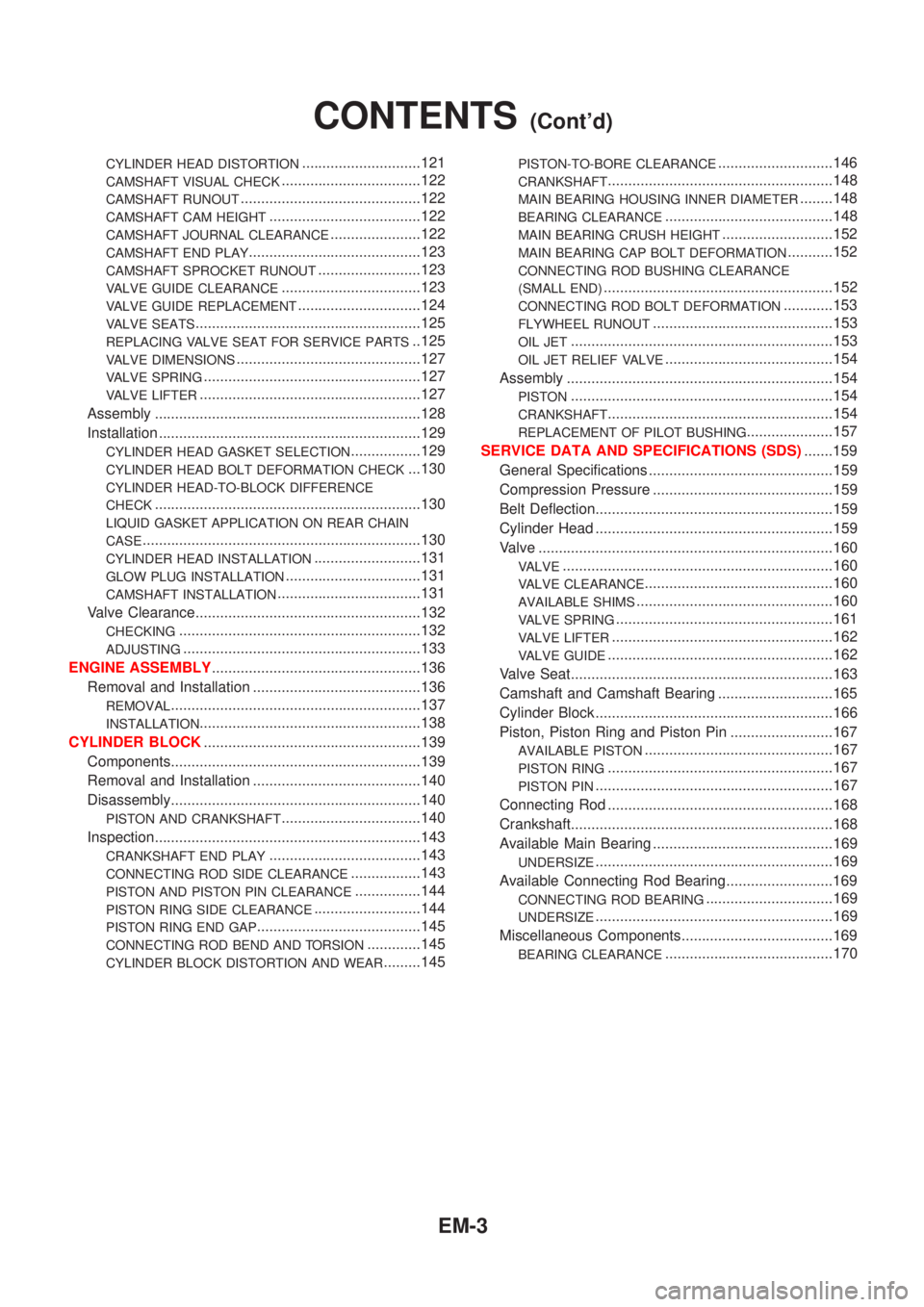
CYLINDER HEAD DISTORTION.............................121
CAMSHAFT VISUAL CHECK..................................122
CAMSHAFT RUNOUT............................................122
CAMSHAFT CAM HEIGHT.....................................122
CAMSHAFT JOURNAL CLEARANCE......................122
CAMSHAFT END PLAY..........................................123
CAMSHAFT SPROCKET RUNOUT.........................123
VALVE GUIDE CLEARANCE..................................123
VALVE GUIDE REPLACEMENT..............................124
VALVE SEATS.......................................................125
REPLACING VALVE SEAT FOR SERVICE PARTS..125
VALVE DIMENSIONS.............................................127
VALVE SPRING.....................................................127
VALVE LIFTER......................................................127
Assembly .................................................................128
Installation ................................................................129
CYLINDER HEAD GASKET SELECTION.................129
CYLINDER HEAD BOLT DEFORMATION CHECK...130
CYLINDER HEAD-TO-BLOCK DIFFERENCE
CHECK
.................................................................130
LIQUID GASKET APPLICATION ON REAR CHAIN
CASE
....................................................................130
CYLINDER HEAD INSTALLATION..........................131
GLOW PLUG INSTALLATION.................................131
CAMSHAFT INSTALLATION...................................131
Valve Clearance.......................................................132
CHECKING...........................................................132
ADJUSTING..........................................................133
ENGINE ASSEMBLY...................................................136
Removal and Installation .........................................136
REMOVAL.............................................................137
INSTALLATION......................................................138
CYLINDER BLOCK.....................................................139
Components.............................................................139
Removal and Installation .........................................140
Disassembly.............................................................140
PISTON AND CRANKSHAFT..................................140
Inspection.................................................................143
CRANKSHAFT END PLAY.....................................143
CONNECTING ROD SIDE CLEARANCE.................143
PISTON AND PISTON PIN CLEARANCE................144
PISTON RING SIDE CLEARANCE..........................144
PISTON RING END GAP........................................145
CONNECTING ROD BEND AND TORSION.............145
CYLINDER BLOCK DISTORTION AND WEAR.........145
PISTON-TO-BORE CLEARANCE............................146
CRANKSHAFT.......................................................148
MAIN BEARING HOUSING INNER DIAMETER........148
BEARING CLEARANCE.........................................148
MAIN BEARING CRUSH HEIGHT...........................152
MAIN BEARING CAP BOLT DEFORMATION...........152
CONNECTING ROD BUSHING CLEARANCE
(SMALL END)
........................................................152
CONNECTING ROD BOLT DEFORMATION............153
FLYWHEEL RUNOUT............................................153
OIL JET................................................................153
OIL JET RELIEF VALVE.........................................154
Assembly .................................................................154
PISTON................................................................154
CRANKSHAFT.......................................................154
REPLACEMENT OF PILOT BUSHING.....................157
SERVICE DATA AND SPECIFICATIONS (SDS).......159
General Specifications .............................................159
Compression Pressure ............................................159
Belt Deflection..........................................................159
Cylinder Head ..........................................................159
Valve ........................................................................160
VALVE..................................................................160
VALVE CLEARANCE..............................................160
AVAILABLE SHIMS................................................160
VALVE SPRING.....................................................161
VALVE LIFTER......................................................162
VALVE GUIDE.......................................................162
Valve Seat................................................................163
Camshaft and Camshaft Bearing ............................165
Cylinder Block ..........................................................166
Piston, Piston Ring and Piston Pin .........................167
AVAILABLE PISTON..............................................167
PISTON RING.......................................................167
PISTON PIN..........................................................167
Connecting Rod .......................................................168
Crankshaft................................................................168
Available Main Bearing ............................................169
UNDERSIZE..........................................................169
Available Connecting Rod Bearing..........................169
CONNECTING ROD BEARING...............................169
UNDERSIZE..........................................................169
Miscellaneous Components.....................................169
BEARING CLEARANCE.........................................170
CONTENTS(Cont'd)
EM-3
Page 114 of 2493

SEM878F
22. Remove cylinder head bolts.
23. Remove cylinder head with manifolds.
+Head warpage or cracking could result from removing in
incorrect order.
+Cylinder head bolts should be loosened in two or three
steps.
SEM914F
DisassemblyNJEM00181. Remove valve components with Tool.
2. Remove valve oil seal with a suitable tool.
SEM915F
InspectionNJEM0019CYLINDER HEAD DISTORTIONNJEM0019S01+Clean surface of cylinder head.
+Use a reliable straightedge and feeler gauge to check the flat-
ness of cylinder head mating surface.
+Check along six positions shown in figure.
Head surface flatness:
Standard: Less than 0.03 mm (0.0012 in)
Limit: 0.1 mm (0.004 in)
If beyond the specified limit, replace or resurface it.
Resurfacing limit:
The limit for cylinder head resurfacing is determined by the
amount of cylinder block resurfacing.
Amount of cylinder head resurfacing is ªAº.
Amount of cylinder block resurfacing is ªBº.
The maximum limit is as follows:
A + B = 0.2 mm (0.008 in)
After resurfacing cylinder head, check that camshaft rotates freely
by hand. If resistance is felt, replace cylinder head.
Nominal cylinder head height:
117.8 - 118.0 mm (4.638 - 4.646 in)
CAMSHAFT VISUAL CHECKNJEM0019S02Check camshaft for scratches, seizure and wear.
CYLINDER HEADQG
Removal (Cont'd)
EM-36
Page 115 of 2493

SEM154D
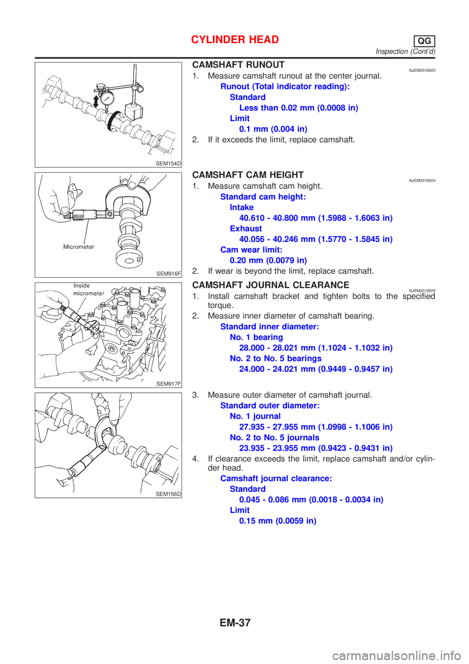
CAMSHAFT RUNOUTNJEM0019S031. Measure camshaft runout at the center journal.
Runout (Total indicator reading):
Standard
Less than 0.02 mm (0.0008 in)
Limit
0.1 mm (0.004 in)
2. If it exceeds the limit, replace camshaft.
SEM916F
CAMSHAFT CAM HEIGHTNJEM0019S041. Measure camshaft cam height.
Standard cam height:
Intake
40.610 - 40.800 mm (1.5988 - 1.6063 in)
Exhaust
40.056 - 40.246 mm (1.5770 - 1.5845 in)
Cam wear limit:
0.20 mm (0.0079 in)
2. If wear is beyond the limit, replace camshaft.
SEM917F
CAMSHAFT JOURNAL CLEARANCENJEM0019S051. Install camshaft bracket and tighten bolts to the specified
torque.
2. Measure inner diameter of camshaft bearing.
Standard inner diameter:
No. 1 bearing
28.000 - 28.021 mm (1.1024 - 1.1032 in)
No. 2 to No. 5 bearings
24.000 - 24.021 mm (0.9449 - 0.9457 in)
SEM156D
3. Measure outer diameter of camshaft journal.
Standard outer diameter:
No. 1 journal
27.935 - 27.955 mm (1.0998 - 1.1006 in)
No. 2 to No. 5 journals
23.935 - 23.955 mm (0.9423 - 0.9431 in)
4. If clearance exceeds the limit, replace camshaft and/or cylin-
der head.
Camshaft journal clearance:
Standard
0.045 - 0.086 mm (0.0018 - 0.0034 in)
Limit
0.15 mm (0.0059 in)
CYLINDER HEADQG
Inspection (Cont'd)
EM-37
Page 119 of 2493

AEM343
8. Use a depth gauge to measure the distance ªLº between the
mounting surface of the cylinder head spring seat and the
valve stem end. If the distance is shorter than specified, repeat
step 5 above to correct it. If the distance is longer, replace the
valve seat.
Valve seat resurface limit:
Intake
35.95 - 36.55 mm (1.4154 - 1.4390 in)
Exhaust
35.92 - 36.52 mm (1.4142 - 1.4378 in)
SEM188A
VALVE DIMENSIONSNJEM0019S12Check dimensions of each valve. Refer to SDS, EM-66 for dimen-
sions.
When valve head has been worn down to 0.5 mm (0.020 in) in
margin thickness, replace valve.
Grinding allowance for valve stem tip is 0.2 mm (0.008 in) or
less.
SEM288A
VALVE SPRINGNJEM0019S13SquarenessNJEM0019S13011. Measure dimension ªSº.
Out-of-square ªSº:
Less than 1.80 mm (0.0709 in)
2. If it exceeds the limit, replace spring.
EM113
PressureNJEM0019S1302Check valve spring pressure at specified spring height.
Pressure:
Standard
370.0 N (37.73 kg, 83.19 lb) at 23.64 mm (0.9307 in)
Limit
More than 347.8 N (35.46 kg, 78.19 lb) at 23.64 mm
(0.9307 in)
If it exceeds the limit, replace spring.
SEM160D
VALVE LIFTER AND VALVE SHIMNJEM0019S161. Check contact and sliding surfaces for wear or scratches.
CYLINDER HEADQG
Inspection (Cont'd)
EM-41
Page 133 of 2493

scratches or seizure. If scratches or seizure is found, hone or
replace the cylinder block.
SEM150B
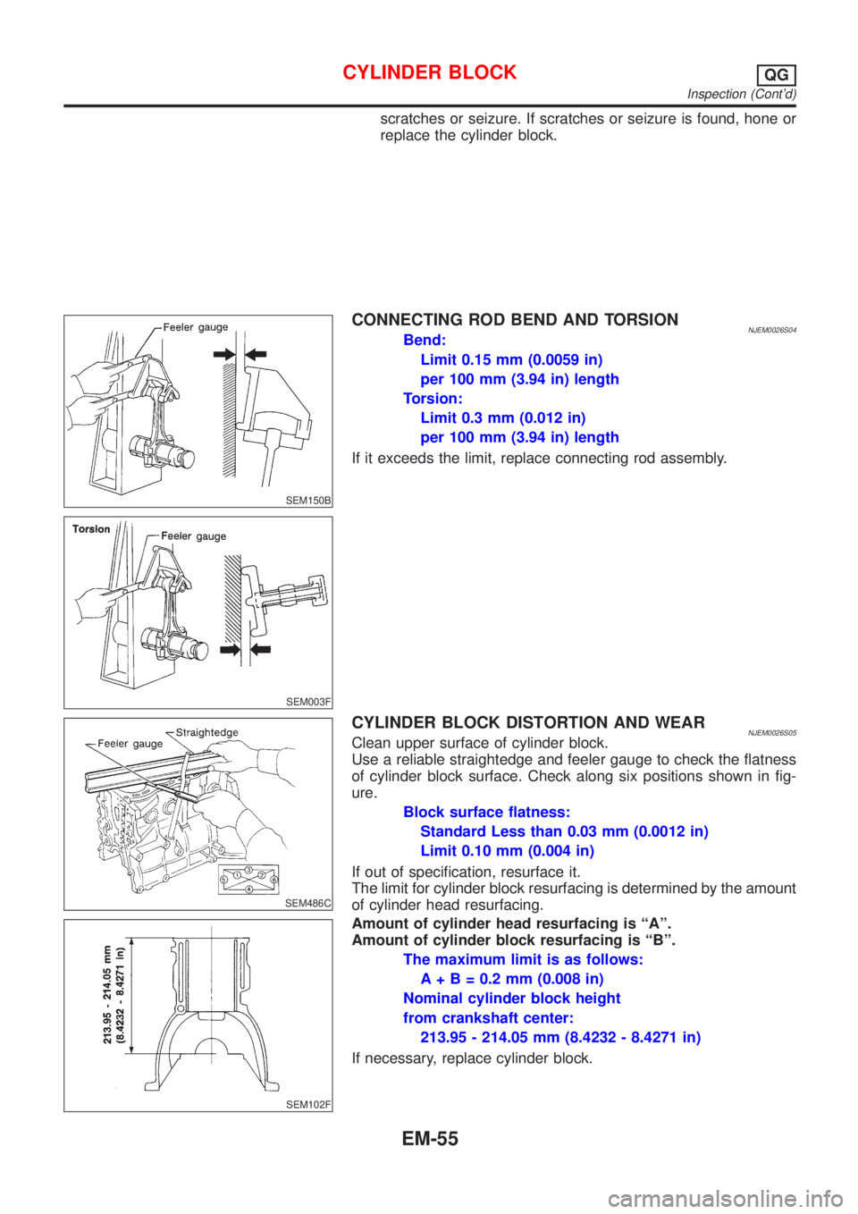
CONNECTING ROD BEND AND TORSIONNJEM0026S04Bend:
Limit 0.15 mm (0.0059 in)
per 100 mm (3.94 in) length
Torsion:
Limit 0.3 mm (0.012 in)
per 100 mm (3.94 in) length
If it exceeds the limit, replace connecting rod assembly.
SEM003F
SEM486C
CYLINDER BLOCK DISTORTION AND WEARNJEM0026S05Clean upper surface of cylinder block.
Use a reliable straightedge and feeler gauge to check the flatness
of cylinder block surface. Check along six positions shown in fig-
ure.
Block surface flatness:
Standard Less than 0.03 mm (0.0012 in)
Limit 0.10 mm (0.004 in)
If out of specification, resurface it.
The limit for cylinder block resurfacing is determined by the amount
of cylinder head resurfacing.
SEM102F
Amount of cylinder head resurfacing is ªAº.
Amount of cylinder block resurfacing is ªBº.
The maximum limit is as follows:
A + B = 0.2 mm (0.008 in)
Nominal cylinder block height
from crankshaft center:
213.95 - 214.05 mm (8.4232 - 8.4271 in)
If necessary, replace cylinder block.
CYLINDER BLOCKQG
Inspection (Cont'd)
EM-55
Page 143 of 2493

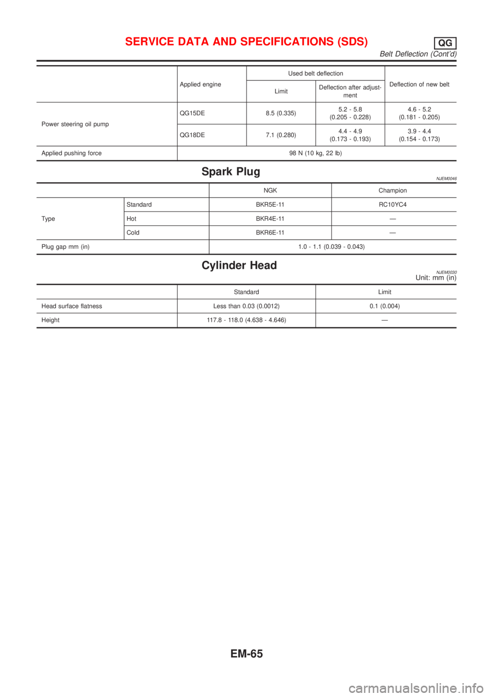
Applied engineUsed belt deflection
Deflection of new belt
LimitDeflection after adjust-
ment
Power steering oil pumpQG15DE 8.5 (0.335)5.2 - 5.8
(0.205 - 0.228)4.6 - 5.2
(0.181 - 0.205)
QG18DE 7.1 (0.280)4.4 - 4.9
(0.173 - 0.193)3.9 - 4.4
(0.154 - 0.173)
Applied pushing force 98 N (10 kg, 22 lb)
Spark PlugNJEM0046
NGK Champion
TypeStandard BKR5E-11 RC10YC4
Hot BKR4E-11 Ð
Cold BKR6E-11 Ð
Plug gap mm (in)1.0 - 1.1 (0.039 - 0.043)
Cylinder HeadNJEM0030Unit: mm (in)
Standard Limit
Head surface flatness Less than 0.03 (0.0012) 0.1 (0.004)
Height 117.8 - 118.0 (4.638 - 4.646) Ð
SERVICE DATA AND SPECIFICATIONS (SDS)QG
Belt Deflection (Cont'd)
EM-65