2001 NISSAN ALMERA N16 manual transmission
[x] Cancel search: manual transmissionPage 12 of 2493

NJGI0002
+The captionsWARNINGandCAUTIONwarm you of steps that must be followed to prevent personal injury
and/or damage to some part of the vehicle.
WARNINGindicates the possibility of personal injury if instructions are not followed.
CAUTIONindicates the possibility of component damage if instructions are not followed.
BOLD TYPED STATEMENTSexceptWARNINGandCAUTIONgive you helpful information.
+ALPHABETICAL INDEXis provided at the end of this manual so that you can rapidly find the item and
page you are searching for.
+A QUICK REFERENCE INDEX, a black tab (e.g.
) is provided on the first page. You can quickly find
the first page of each section by matching it to the section's black tab.
+THE CONTENTSare listed on the first page of each section.
+THE TITLEis indicated on the upper portion of each page and shows the part or system.
+THE PAGE NUMBERof each section consists of two letters which designate the particular section and a
number (e.g. ªBR-5º).
+THE LARGE ILLUSTRATIONSare exploded views (See below.) and contain tightening torques, lubrica-
tion points, section number of thePARTS CATALOG(e.g. SEC. 440) and other information necessary to
perform repairs.
The illustrations should be used in reference to service matters only. When ordering parts, refer to the
appropriatePARTS CATALOG.
SBR364AC
+THE SMALL ILLUSTRATIONSshow the important steps such as inspection, use of special tools, knacks
of work and hidden or tricky steps which are not shown in the previous large illustrations.
Assembly, inspection and adjustment procedures for the complicated units such as the automatic transaxle
or transmission, etc. are presented in a step-by-step format where necessary.
+TheUNITSgiven in this manual are primarily expressed as the SI UNIT (International System of Unit),
and alternatively expressed in the metric system and in the yard/pound system.
ªExampleº
Tightening torque:
59 - 78 N´m (6.0 - 8.0 kg-m, 43 - 58 ft-lb)
+TROUBLE DIAGNOSESare included in sections dealing with complicated components.
HOW TO USE THIS MANUAL
GI-10
Page 13 of 2493

+SERVICE DATA AND SPECIFICATIONSare contained at the end of each section for quick reference of
data.
+The followingSYMBOLS AND ABBREVIATIONSare used:
SYMBOL ABBREVIATION SYMBOL ABBREVIATION
Tightening torque
2WD2-Wheel Drive
Should be lubricated with grease. Unless oth-
erwise indicated, use recommended multi-pur-
pose grease.A/CAir Conditioner
Should be lubricated with oil. P/S Power Steering
Sealing point SST Special Service Tools
Checking point SAE Society of Automotive Engineers, Inc.
Always replace after every disassembly. ATF Automatic Transmission Fluid
jP
Apply petroleum jelly.
D1Drive range 1st gear
Apply ATF. D2Drive range 2nd gear
HSelect with proper thickness. D
3Drive range 3rd gear
IAdjustment is required. D
4Drive range 4th gear
SDS Service Data and Specifications OD Overdrive
LH, RH Left-Hand, Right-Hand 2
22nd range 2nd gear
FR, RR Front, Rear 2
12nd range 1st gear
M/T Manual Transaxle/Transmission 1
21st range 2nd gear
A/T Automatic Transaxle/Transmission 1
11st range 1st gear
HOW TO USE THIS MANUAL
GI-11
Page 23 of 2493

NJGI0005
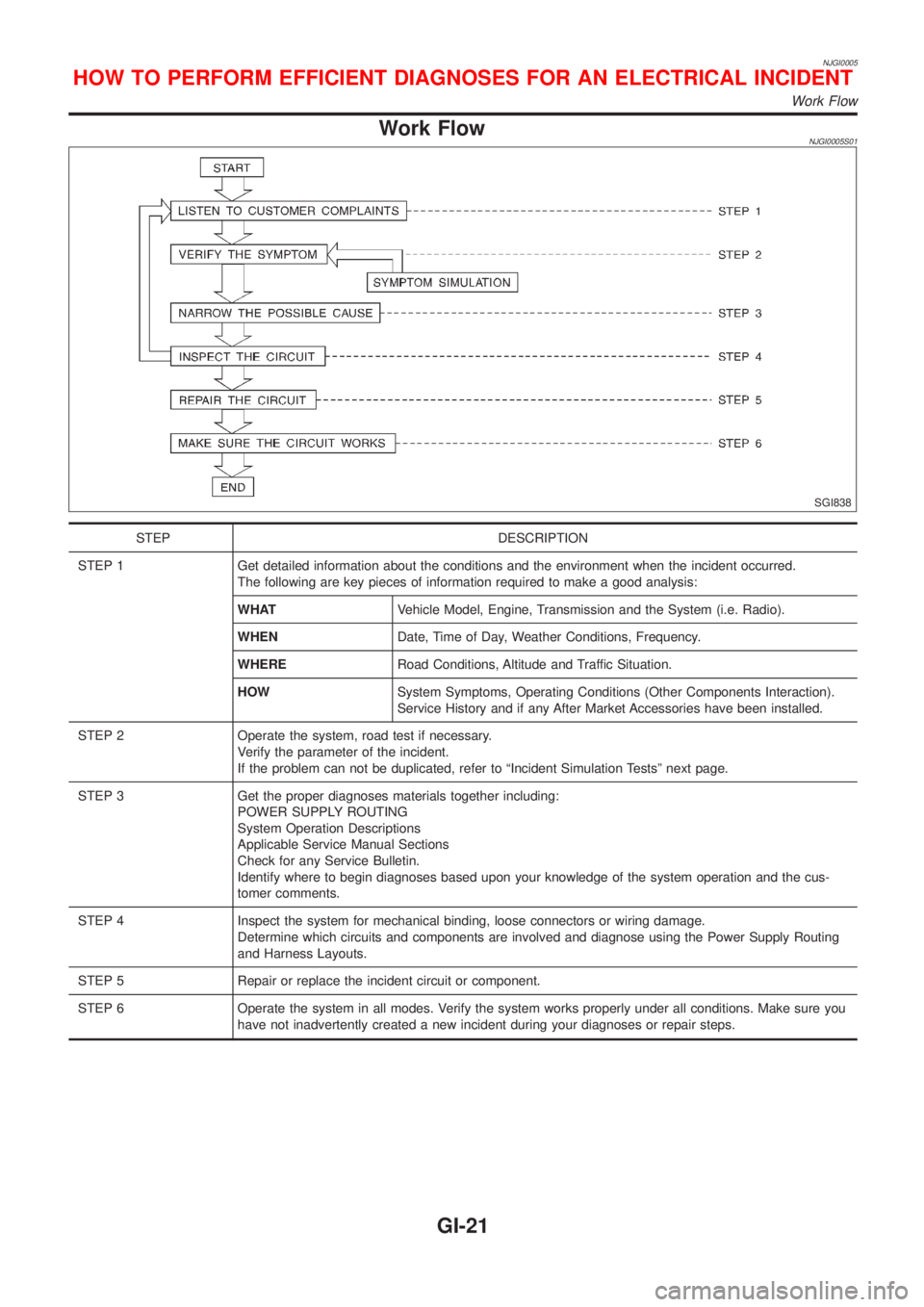
Work FlowNJGI0005S01
SGI838
STEP DESCRIPTION
STEP 1 Get detailed information about the conditions and the environment when the incident occurred.
The following are key pieces of information required to make a good analysis:
WHATVehicle Model, Engine, Transmission and the System (i.e. Radio).
WHENDate, Time of Day, Weather Conditions, Frequency.
WHERERoad Conditions, Altitude and Traffic Situation.
HOWSystem Symptoms, Operating Conditions (Other Components Interaction).
Service History and if any After Market Accessories have been installed.
STEP 2 Operate the system, road test if necessary.
Verify the parameter of the incident.
If the problem can not be duplicated, refer to ªIncident Simulation Testsº next page.
STEP 3 Get the proper diagnoses materials together including:
POWER SUPPLY ROUTING
System Operation Descriptions
Applicable Service Manual Sections
Check for any Service Bulletin.
Identify where to begin diagnoses based upon your knowledge of the system operation and the cus-
tomer comments.
STEP 4 Inspect the system for mechanical binding, loose connectors or wiring damage.
Determine which circuits and components are involved and diagnose using the Power Supply Routing
and Harness Layouts.
STEP 5 Repair or replace the incident circuit or component.
STEP 6 Operate the system in all modes. Verify the system works properly under all conditions. Make sure you
have not inadvertently created a new incident during your diagnoses or repair steps.
HOW TO PERFORM EFFICIENT DIAGNOSES FOR AN ELECTRICAL INCIDENT
Work Flow
GI-21
Page 49 of 2493

SGI805
SGI987
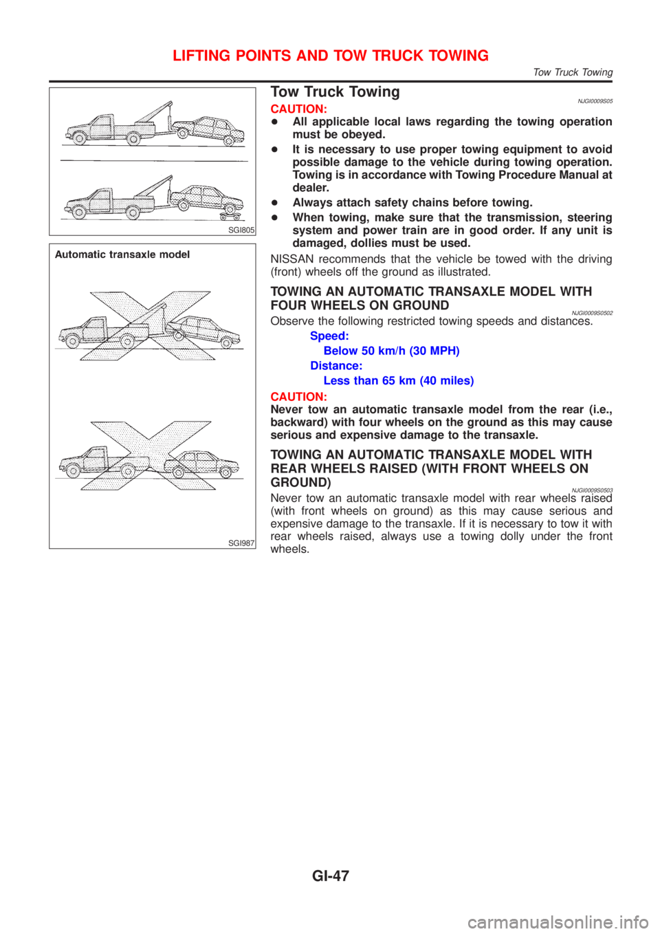
Tow Truck TowingNJGI0009S05CAUTION:
+All applicable local laws regarding the towing operation
must be obeyed.
+It is necessary to use proper towing equipment to avoid
possible damage to the vehicle during towing operation.
Towing is in accordance with Towing Procedure Manual at
dealer.
+Always attach safety chains before towing.
+When towing, make sure that the transmission, steering
system and power train are in good order. If any unit is
damaged, dollies must be used.
NISSAN recommends that the vehicle be towed with the driving
(front) wheels off the ground as illustrated.
TOWING AN AUTOMATIC TRANSAXLE MODEL WITH
FOUR WHEELS ON GROUND
NJGI0009S0502Observe the following restricted towing speeds and distances.
Speed:
Below 50 km/h (30 MPH)
Distance:
Less than 65 km (40 miles)
CAUTION:
Never tow an automatic transaxle model from the rear (i.e.,
backward) with four wheels on the ground as this may cause
serious and expensive damage to the transaxle.
TOWING AN AUTOMATIC TRANSAXLE MODEL WITH
REAR WHEELS RAISED (WITH FRONT WHEELS ON
GROUND)
NJGI0009S0503Never tow an automatic transaxle model with rear wheels raised
(with front wheels on ground) as this may cause serious and
expensive damage to the transaxle. If it is necessary to tow it with
rear wheels raised, always use a towing dolly under the front
wheels.
LIFTING POINTS AND TOW TRUCK TOWING
Tow Truck Towing
GI-47
Page 58 of 2493

NJMA0036
Shown below are Pre-delivery Inspection Items required for the new vehicle. It is recommended that
necessary items other than those listed here be added, paying due regard to the conditions in each
country.
Perform applicable items on each model. Consult text of this section for specifications.
UNDER HOOD Ð engine off
Radiator coolant level and coolant hose connections for leaks
Battery fluid level, specific gravity and conditions of battery terminals
Drive belts tension
Fuel filter for water or dusts (Diesel only), and fuel lines and connections for leaks
Engine oil level and oil leaks
Clutch and brake reservoir fluid level and fluid lines for leaks
Windshield and rear window washer and headlamp cleaner reservoir fluid level
Power steering reservoir fluid level and hose connections for leaks
ON INSIDE AND OUTSIDE
Remove front spring/strut spacer (If applicable)
Operation of all instruments, gauges, lights and accessories
Operation of horn(s), wiper and washer
Steering lock for operation
Check air conditioner for gas leaks
Front and rear seats, and seat belts for operation
All moldings, trims and fittings for fit and alignment
All windows for operation and alignment
Hood, trunk lid, door panels for fit and alignment
Latches, keys and locks for operation
Weatherstrips for adhesion and fit
Headlamp aiming
Tighten wheel nuts (Inc. inner nuts if applicable)
Tire pressure (Inc. spare tire)
Check front wheels for toe-in
Install clock/voltmeter/room lamp fuse (If applicable)
Install deodorizing filter to air conditioner (If applicable)
Remove wiper blade protectors (If applicable)
UNDER BODY
Manual transmission/transaxle, transfer and differential gear oil level
Brake and fuel lines and oil/fluid reservoirs for leaks
Tighten bolts and nuts of steering linkage and gear box, suspension, propeller shafts and drive shafts
Tighten rear body bolts and nuts (Models with wooden bed only)
ROAD TEST
Clutch operation
Parking brake operation
Service brake operation
Automatic transmission/transaxle shift timing and kickdown
Steering control and returnability
Engine performance
Squeaks and rattles
ENGINE OPERATING AND HOT
Adjust idle speed
Automatic transmission/transaxle fluid level
Engine idling and stop knob operation (Diesel only)
FINAL INSPECTION
Install necessary parts (outside mirror, wheel covers, seat belts, mat, carpet or mud flaps)
Inspect for interior and exterior metal and paint damage
Check for spare tire, jack, tools (wheel chock), and literature
Wash, clean interior and exterior
: Not applicable to this model
PRE-DELIVERY INSPECTION ITEMS
MA-2
Page 76 of 2493

NJMA0006
Fluids and LubricantsNJMA0006S01
Recommended fluids and lubricants
Engine oilQG engine+Except for Europe
API SE, SF, SG, SH or SJ*1
ILSAC grade GF-I or GF-II*1
+For Europe
API SG, SH or SJ*1
ILSAC grade GF-I or GF-II*1
ACEA 96-A2
YD engine+Except for Europe
API CD, CE, CF or CF-4*1, *2
+For Europe
API CF-4*1, *2
ACEA 98-B1
Cooling system+Except for Europe
Nissan genuine engine coolant, or equivalent in its quality*3
+For Europe
Genuine Nissan Anti-freeze Coolant (L2N) or equivalent*3
Manual transaxle gear oil+Except for Europe
API GL-4
Viscosity SAE 75W-90
+For Europe
Genuine Nissan XZ gear oil or exact equivalent.
Automatic transaxle fluid Genuine Nissan ATF or equivalent*4
Power steering fluid Type Dexron
TMIII or equivalent
Brake and clutch fluid+Except for Europe
DOT 3 (US FMVSS No. 116)
+For Europe
DOT 3 or DOT 4 (US FMVSS No. 116)*5
Multi-purpose grease NLGI No. 2 (Lithium soap base)
*1: For further details, see ªSAE Viscosity Numberº.
*2: Never use API CG-4.
*3: Use Nissan genuine engine coolant [For Europe, use Genuine Nissan Anti-freeze Coolant (L2N)] or equivalent in its quality, in order
to avoid possible aluminum corrosion within the engine cooling system caused by the use of non-genuine engine coolant.
Note that any repairs for the incidents within the engine cooling system while using non-genuine engine coolant may not be
covered by the warranty even if such incidents occurred during the warranty period.
*4: Contact a Nissan dealership for more information regarding suitable fluids, including recommended brand(s) of Dexron
TMIII/MerconTM
Automatic Transmission Fluid.
*5: Never mix different types of fluids (DOT 3 and DOT 4).
RECOMMENDED FLUIDS AND LUBRICANTS
Fluids and Lubricants
MA-20
Page 312 of 2493

Supplemental Restraint System (SRS) ªAIR
BAGº and ªSEAT BELT PRE-TENSIONERº
NJEC0002The Supplemental Restraint System such as ªAIR BAGº and ªSEAT BELT PRE-TENSIONERº used along with
a seat belt, helps to reduce the risk or severity of injury to the driver and front passenger for certain types of
collision. The SRS system composition which is available to NISSAN MODEL N16 is as follows (The compo-
sition varies according to the destination and optional equipment.):
+For a frontal collision
The Supplemental Restraint System consists of driver air bag module (located in the center of the steer-
ing wheel), front passenger air bag module (located on the instrument panel on passenger side), front seat
belt pre-tensioners, a diagnoses sensor unit, warning lamp, wiring harness and spiral cable.
+For a side collision
The Supplemental Restraint System consists of front side air bag module (located in the outer side of front
seat), side air bag (satellite) sensor, diagnoses sensor unit (one of components of air bags for a frontal
collision), wiring harness, warning lamp (one of components of air bags for a frontal collision).
Information necessary to service the system safely is included in theRS sectionof this Service Manual.
WARNING:
+To avoid rendering the SRS inoperative, which could increase the risk of personal injury or death
in the event of a collision which would result in air bag inflation, all maintenance should be per-
formed by an authorized NISSAN dealer.
+Improper maintenance, including incorrect removal and installation of the SRS, can lead to per-
sonal injury caused by unintentional activation of the system. For removal of Spiral Cable and Air
Bag Module, see the RS section.
+Do not use electrical test equipment on any circuit related to the SRS unless instructed to in this
Service Manual. SRS wiring harness can be identified by yellow harness connector.
Precautions for On Board Diagnostic (OBD)
System of Engine and A/T
NJEC0003The ECM has an on board diagnostic system. It will light up the malfunction indicator (MI) to warn the driver
of a malfunction causing emission deterioration.
CAUTION:
+Be sure to turn the ignition switch ªOFFº and disconnect the negative battery terminal before any
repair or inspection work. The open/short circuit of related switches, sensors, solenoid valves, etc.
will cause the MI to light up.
+Be sure to connect and lock the connectors securely after work. A loose (unlocked) connector will
cause the MI to light up due to the open circuit. (Be sure the connector is free from water, grease,
dirt, bent terminals, etc.)
+Certain systems and components, especially those related to OBD, may use a new style slide-
locking type harness connector.
For description and how to disconnect, refer to EL section, ªDescriptionº, ªHARNESS CONNEC-
TORº.
+Be sure to route and secure the harnesses properly after work. The interference of the harness with
a bracket, etc. may cause the MI to light up due to the short circuit.
+Be sure to connect rubber tubes properly after work. A misconnected or disconnected rubber tube
may cause the MI to light up due to the malfunction of fuel injection system, etc.
+Be sure to erase the unnecessary malfunction information (repairs completed) from the ECM and
TCM (Transmission Control Module) before returning the vehicle to the customer.
PRECAUTIONSQG
Supplemental Restraint System (SRS) ªAIR BAGº and ªSEAT BELT PRE-TENSIONERº
EC-16
Page 1529 of 2493

SAT992C
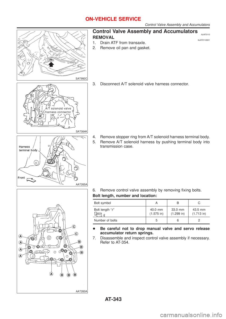
Control Valve Assembly and AccumulatorsNJAT0110REMOVALNJAT0110S011. Drain ATF from transaxle.
2. Remove oil pan and gasket.
SAT064K
3. Disconnect A/T solenoid valve harness connector.
AAT265A
4. Remove stopper ring from A/T solenoid harness terminal body.
5. Remove A/T solenoid harness by pushing terminal body into
transmission case.
AAT260A
6. Remove control valve assembly by removing fixing bolts.
Bolt length, number and location:
Bolt symbol A B C
Bolt length ª!º
40.0 mm
(1.575 in)33.0 mm
(1.299 in)43.5 mm
(1.713 in)
Number of bolts 5 6 2
+Be careful not to drop manual valve and servo release
accumulator return springs.
7. Disassemble and inspect control valve assembly if necessary.
Refer to AT-354.
ON-VEHICLE SERVICE
Control Valve Assembly and Accumulators
AT-343