2001 NISSAN ALMERA N16 Ignition
[x] Cancel search: IgnitionPage 5 of 2493

PrecautionsNJGI0001Observe the following precautions to ensure safe and proper
servicing. These precautions are not described in each indi-
vidual section.
SGI646
PRECAUTIONS FOR SUPPLEMENTAL RESTRAINT
SYSTEM (SRS) ªAIR BAGº AND ªSEAT BELT
PRE-TENSIONERº
NJGI0001S01The Supplemental Restraint System such as ªAIR BAGº and ªSEAT
BELT PRE-TENSIONERº used along with a seat belt, helps to
reduce the risk or severity of injury to the driver and front passen-
ger for certain types of collision. The SRS system composition
which is available to NISSAN MODEL N16 is as follows (The com-
position varies according to the destination and optional equip-
ment.):
+For a frontal collision
The Supplemental Restraint System consists of driver air bag
module (located in the center of the steering wheel), front pas-
senger air bag module (located on the instrument panel on
passenger side), front seat belt pre-tensioners, a diagnoses
sensor unit, warning lamp, wiring harness and spiral cable.
+For a side collision
The Supplemental Restraint System consists of front side air
bag module (located in the outer side of front seat), side air bag
(satellite) sensor, diagnoses sensor unit (one of components of
air bags for a frontal collision), wiring harness, warning lamp
(one of components of air bags for a frontal collision).
Information necessary to service the system safely is included in
theRS sectionof this Service Manual.
WARNING:
+To avoid rendering the SRS inoperative, which could
increase the risk of personal injury or death in the event
of a collision which would result in air bag inflation, all
maintenance should be performed by an authorized
NISSAN dealer.
+Improper maintenance, including incorrect removal and
installation of the SRS, can lead to personal injury caused
by unintentional activation of the system. For removal of
Spiral Cable and Air Bag Module, see the RS section.
+Do not use electrical test equipment on any circuit related
to the SRS unless instructed to in this Service Manual.
SRS wiring harnesses can be identified by yellow harness
connector.
PRECAUTIONS FOR NATS (NISSAN ANTI-THEFT
SYSTEM)
NJGI0001S02NATS will immobilize the engine if someone tries to start it without
the registered key of NATS.
Both of the originally supplied ignition key IDs have been NATS
registered.
PRECAUTIONS
Precautions
GI-3
Page 6 of 2493

The security indicator is located on the combi meter. The indicator
blinks when the ignition switch is in ªOFFº or ªACCº position.
Therefore, NATS warns outsiders that the vehicle is equipped with
the anti-theft system.
+When NATS detects trouble, the security indicator lamp lights
up while ignition switch is in ªONº position.
This lighting up indicates that the anti-theft is not functioning,
so prompt service is required.
+When servicing NATS (trouble diagnoses, system initialization
and additional registration of other NATS ignition key IDs),
CONSULT-II hardware and CONSULT-II NATS software is
necessary.
Regarding the procedures of NATS initialization and NATS
ignition key ID registration, refer to CONSULT-II operation
manual, NATS.
Therefore, CONSULT-II NATS software (program card and
operation manual) must be kept strictly confidential to main-
tain the integrity of the anti-theft function.
+When servicing NATS (trouble diagnoses, system initialization
and additional registration of other NATS ignition key IDs), it
may be necessary to re-register original key identification.
Therefore, be sure to receive all keys from vehicle owner. A
maximum of five key IDs can be registered into NATS.
+When failing to start the engine first time using the key of
NATS, start as follows.
a) Leave the ignition key in ªONº position for approximately 5
seconds.
b) Turn ignition key to ªOFFº or ªLOCKº position and wait approxi-
mately 5 seconds.
c) Repeat step 1 and 2 again.
d) Restart the engine while keeping the key separate from any
others on key-chain.
SGI285
GENERAL PRECAUTIONSNJGI0001S03+Do not operate the engine for an extended period of time
without proper exhaust ventilation.
Keep the work area well ventilated and free of any inflammable
materials. Special care should be taken when handling any
inflammable or poisonous materials, such as gasoline, refrig-
erant gas, etc. When working in a pit or other enclosed area,
be sure to properly ventilate the area before working with haz-
ardous materials.
Do not smoke while working on the vehicle.
SGI231
+Before jacking up the vehicle, apply wheel chocks or other tire
blocks to the wheels to prevent the vehicle from moving. After
jacking up the vehicle, support the vehicle weight with safety
stands at the points designated for proper lifting before work-
ing on the vehicle.
These operations should be done on a level surface.
+When removing a heavy component such as the engine or
transaxle, be careful not to lose your balance and drop them.
Also, do not allow them to strike adjacent parts, especially the
brake tubes and master cylinder.
PRECAUTIONS
Precautions (Cont'd)
GI-4
Page 7 of 2493

SEF289H
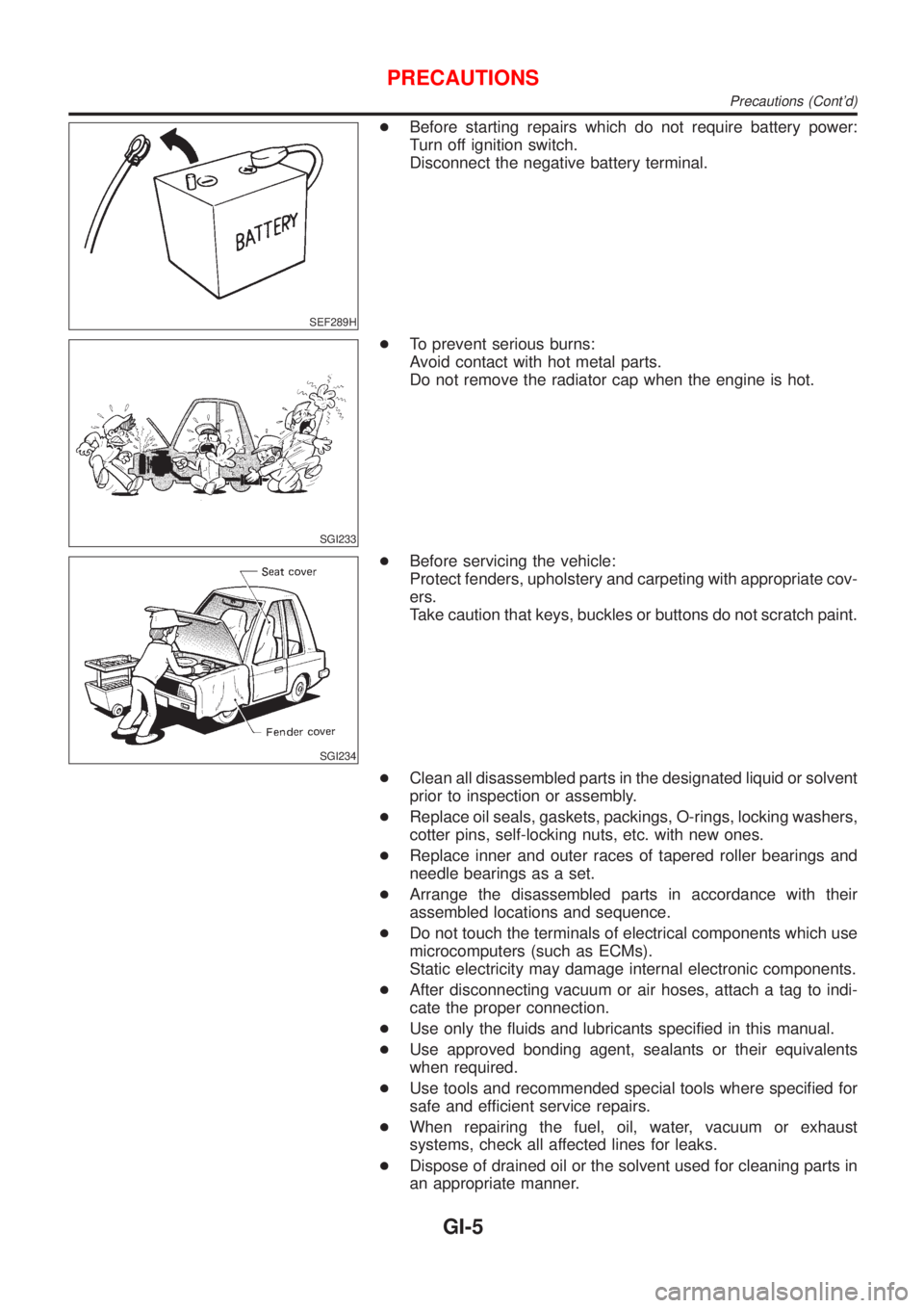
+Before starting repairs which do not require battery power:
Turn off ignition switch.
Disconnect the negative battery terminal.
SGI233
+To prevent serious burns:
Avoid contact with hot metal parts.
Do not remove the radiator cap when the engine is hot.
SGI234
+Before servicing the vehicle:
Protect fenders, upholstery and carpeting with appropriate cov-
ers.
Take caution that keys, buckles or buttons do not scratch paint.
+Clean all disassembled parts in the designated liquid or solvent
prior to inspection or assembly.
+Replace oil seals, gaskets, packings, O-rings, locking washers,
cotter pins, self-locking nuts, etc. with new ones.
+Replace inner and outer races of tapered roller bearings and
needle bearings as a set.
+Arrange the disassembled parts in accordance with their
assembled locations and sequence.
+Do not touch the terminals of electrical components which use
microcomputers (such as ECMs).
Static electricity may damage internal electronic components.
+After disconnecting vacuum or air hoses, attach a tag to indi-
cate the proper connection.
+Use only the fluids and lubricants specified in this manual.
+Use approved bonding agent, sealants or their equivalents
when required.
+Use tools and recommended special tools where specified for
safe and efficient service repairs.
+When repairing the fuel, oil, water, vacuum or exhaust
systems, check all affected lines for leaks.
+Dispose of drained oil or the solvent used for cleaning parts in
an appropriate manner.
PRECAUTIONS
Precautions (Cont'd)
GI-5
Page 8 of 2493

Do not attempt to top off the fuel tank after the fuel pump nozzle
shuts off automatically. Continued refueling may cause fuel
overflow, resulting in fuel spray and possibly a fire.
WARNING:
To prevent ECM from storing the diagnostic trouble codes, do
not carelessly disconnect the harness connectors which are
related to the engine control system and TCM (Transmission
Control Module) system. The connectors should be discon-
nected only when working according to the WORK FLOW of
TROUBLE DIAGNOSES in EC and AT sections.
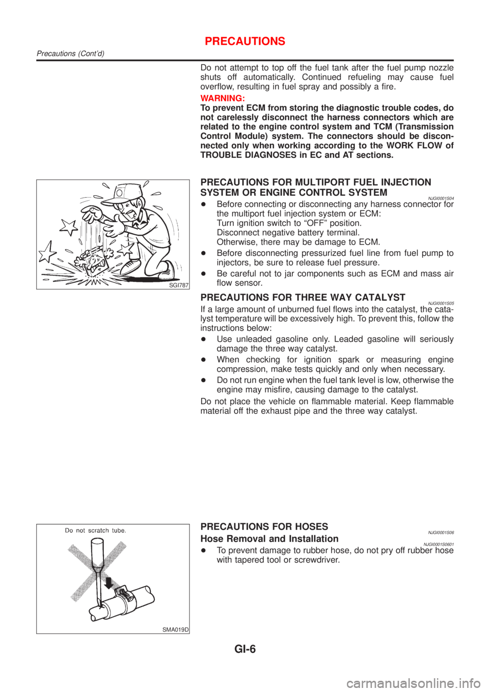
SGI787
PRECAUTIONS FOR MULTIPORT FUEL INJECTION
SYSTEM OR ENGINE CONTROL SYSTEM
NJGI0001S04+Before connecting or disconnecting any harness connector for
the multiport fuel injection system or ECM:
Turn ignition switch to ªOFFº position.
Disconnect negative battery terminal.
Otherwise, there may be damage to ECM.
+Before disconnecting pressurized fuel line from fuel pump to
injectors, be sure to release fuel pressure.
+Be careful not to jar components such as ECM and mass air
flow sensor.
PRECAUTIONS FOR THREE WAY CATALYSTNJGI0001S05If a large amount of unburned fuel flows into the catalyst, the cata-
lyst temperature will be excessively high. To prevent this, follow the
instructions below:
+Use unleaded gasoline only. Leaded gasoline will seriously
damage the three way catalyst.
+When checking for ignition spark or measuring engine
compression, make tests quickly and only when necessary.
+Do not run engine when the fuel tank level is low, otherwise the
engine may misfire, causing damage to the catalyst.
Do not place the vehicle on flammable material. Keep flammable
material off the exhaust pipe and the three way catalyst.
SMA019D
PRECAUTIONS FOR HOSESNJGI0001S06Hose Removal and InstallationNJGI0001S0601+To prevent damage to rubber hose, do not pry off rubber hose
with tapered tool or screwdriver.
PRECAUTIONS
Precautions (Cont'd)
GI-6
Page 19 of 2493

AGI070
HARNESS INDICATIONNJGI0003S0202+Letter designations next to test meter probe indicate harness
(connector) wire color.
+Connector numbers in a single circle M33 indicate harness
connectors.
COMPONENT INDICATIONNJGI0003S0203+Connector numbers in a double circle F211 indicate compo-
nent connectors.
SGI860
SWITCH POSITIONSNJGI0003S0204Switches are shown in wiring diagrams as if the vehicle is in the
ªnormalº condition.
A vehicle is in the ªnormalº condition when:
+ignition switch is ªOFFº,
+doors, hood and trunk lid/back door are closed,
+pedals are not depressed, and
+parking brake is released.
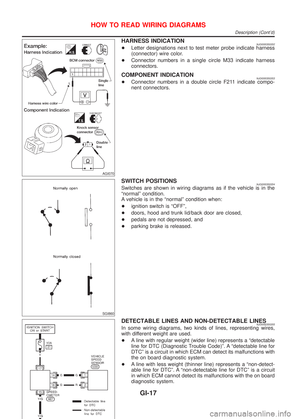
DETECTABLE LINES AND NON-DETECTABLE LINESNJGI0003S0205In some wiring diagrams, two kinds of lines, representing wires,
with different weight are used.
+A line with regular weight (wider line) represents a ªdetectable
line for DTC (Diagnostic Trouble Code)º. A ªdetectable line for
DTCº is a circuit in which ECM can detect its malfunctions with
the on board diagnostic system.
+A line with less weight (thinner line) represents a ªnon-detect-
able line for DTCº. A ªnon-detectable line for DTCº is a circuit
in which ECM cannot detect its malfunctions with the on board
diagnostic system.
HOW TO READ WIRING DIAGRAMS
Description (Cont'd)
GI-17
Page 28 of 2493

voltage; open is further down the circuit than the relay.
no voltage; open is between SW1 and relay (point B).
5) Close the relay and probe at the solenoid.
voltage; open is further down the circuit than the solenoid.
no voltage; open is between relay and solenoid (point C).
Any powered circuit can be diagnosed using the approach in the
above example.
TESTING FOR ªSHORTSº IN THE CIRCUITNJGI0005S0303To simplify the discussion of shorts in the system please refer to
the schematic below.
SGI847
Resistance Check Method
1) Disconnect the battery negative cable and remove the blown
fuse.
2) Disconnect all loads (SW1 open, relay disconnected and sole-
noid disconnected) powered through the fuse.
3) Connect one probe of the ohmmeter to the load side of the fuse
terminal. Connect the other probe to a known good ground.
4) With SW1 open, check for continuity.
continuity; short is between fuse terminal and SW1 (point A).
no continuity; short is further down the circuit than SW1.
5) Close SW1 and disconnect the relay. Put probes at the load
side of fuse terminal and a known good ground. Then, check
for continuity.
continuity; short is between SW1 and the relay (point B).
no continuity; short is further down the circuit than the relay.
6) Close SW1 and jump the relay contacts with jumper wire. Put
probes at the load side of fuse terminal and a known good
ground. Then, check for continuity.
continuity; short is between relay and solenoid (point C).
no continuity; check solenoid, retrace steps.
Voltage Check Method
1) Remove the blown fuse and disconnect all loads (i.e. SW1
open, relay disconnected and solenoid disconnected) powered
through the fuse.
2) Turn the ignition key to the ON or START position. Verify bat-
tery voltage at the B + side of the fuse terminal (one lead on
the B + terminal side of the fuse block and one lead on a known
good ground).
3) With SW1 open and the DMM leads across both fuse
terminals, check for voltage.
voltage; short is between fuse block and SW1 (point A).
no voltage; short is further down the circuit than SW1.
4) With SW1 closed, relay and solenoid disconnected and the
DMM leads across both fuse terminals, check for voltage.
voltage; short is between SW1 and the relay (point B).
HOW TO PERFORM EFFICIENT DIAGNOSES FOR AN ELECTRICAL INCIDENT
Circuit Inspection (Cont'd)
GI-26
Page 33 of 2493

NJGI0006
NOTICE:
Trouble diagnoses indicate work procedures required to diagnose
problems effectively. Observe the following instructions before
diagnosing.
1)Before performing trouble diagnoses, read the ªPrelimi-
nary Checkº, the ªSymptom Chartº or the ªWork Flowº.
2)After repairs, re-check that the problem has been com-
pletely eliminated.
3)Refer to Component Parts and Harness Connector Loca-
tion for the Systems described in each section for
identification/location of components and harness con-
nectors.
4)Refer to the Circuit Diagram for quick pinpoint check.
If you need to check circuit continuity between harness
connectors in more detail, such as when a sub-harness is
used, refer to Wiring Diagram in each individual section
and Harness Layout in EL section for identification of har-
ness connectors.
5)When checking circuit continuity, ignition switch should
be OFF.
6)Before checking voltage at connectors, check battery volt-
age.
7)After accomplishing the Diagnostic Procedures and Elec-
trical Components Inspection, make sure that all harness
connectors are reconnected as they were.
HOW TO FOLLOW TROUBLE DIAGNOSES
GI-31
Page 35 of 2493

Key to Symbols Signifying Measurements or
Procedures
NJGI0006S02
Symbol Symbol explanation Symbol Symbol explanation
Check after disconnecting the con-
nector to be measured.Procedure with Generic Scan Tool
(GST, OBD-II scan tool)
Check after connecting the connec-
tor to be measured.Procedure without CONSULT-II or
GST
Insert key into ignition switch.A/C switch is ªOFFº.
Remove key from ignition switch.A/C switch is ªONº.
Turn ignition switch to ªOFFº posi-
tion.REC switch is ªONº.
Turn ignition switch to ªONº position.REC switch is ªOFFº.
Turn ignition switch to ªSTARTº posi-
tion.Fan switch is ªONº. (At any position
except for ªOFFº position)
Turn ignition switch from ªOFFº to
ªACCº position.Fan switch is ªOFFº.
Turn ignition switch from ªACCº to
ªOFFº position.Apply positive voltage from battery
with fuse directly to components.
Turn ignition switch from ªOFFº to
ªONº position.Drive vehicle.
Turn ignition switch from ªONº to
ªOFFº position.Disconnect battery negative cable.
Do not start engine, or check with
engine stopped.Depress brake pedal.
Start engine, or check with engine
running.Release brake pedal.
Apply parking brake.Depress accelerator pedal.
Release parking brake.Release accelerator pedal.
HOW TO FOLLOW TROUBLE DIAGNOSES
Key to Symbols Signifying Measurements or Procedures
GI-33