2001 NISSAN ALMERA N16 radio
[x] Cancel search: radioPage 23 of 2493
NJGI0005
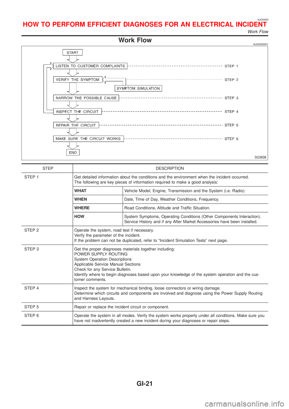
Work FlowNJGI0005S01
SGI838
STEP DESCRIPTION
STEP 1 Get detailed information about the conditions and the environment when the incident occurred.
The following are key pieces of information required to make a good analysis:
WHATVehicle Model, Engine, Transmission and the System (i.e. Radio).
WHENDate, Time of Day, Weather Conditions, Frequency.
WHERERoad Conditions, Altitude and Traffic Situation.
HOWSystem Symptoms, Operating Conditions (Other Components Interaction).
Service History and if any After Market Accessories have been installed.
STEP 2 Operate the system, road test if necessary.
Verify the parameter of the incident.
If the problem can not be duplicated, refer to ªIncident Simulation Testsº next page.
STEP 3 Get the proper diagnoses materials together including:
POWER SUPPLY ROUTING
System Operation Descriptions
Applicable Service Manual Sections
Check for any Service Bulletin.
Identify where to begin diagnoses based upon your knowledge of the system operation and the cus-
tomer comments.
STEP 4 Inspect the system for mechanical binding, loose connectors or wiring damage.
Determine which circuits and components are involved and diagnose using the Power Supply Routing
and Harness Layouts.
STEP 5 Repair or replace the incident circuit or component.
STEP 6 Operate the system in all modes. Verify the system works properly under all conditions. Make sure you
have not inadvertently created a new incident during your diagnoses or repair steps.
HOW TO PERFORM EFFICIENT DIAGNOSES FOR AN ELECTRICAL INCIDENT
Work Flow
GI-21
Page 26 of 2493
The second method is to put the suspect component into a freezer
long enough for any water to freeze. Reinstall the part into the car
and check for the reoccurrence of the incident. If it occurs, repair
or replace the component.
SGI844
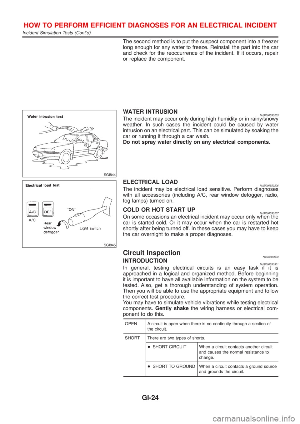
WATER INTRUSIONNJGI0005S0205The incident may occur only during high humidity or in rainy/snowy
weather. In such cases the incident could be caused by water
intrusion on an electrical part. This can be simulated by soaking the
car or running it through a car wash.
Do not spray water directly on any electrical components.
SGI845
ELECTRICAL LOADNJGI0005S0206The incident may be electrical load sensitive. Perform diagnoses
with all accessories (including A/C, rear window defogger, radio,
fog lamps) turned on.
COLD OR HOT START UPNJGI0005S0207On some occasions an electrical incident may occur only when the
car is started cold. Or it may occur when the car is restarted hot
shortly after being turned off. In these cases you may have to keep
the car overnight to make a proper diagnoses.
Circuit InspectionNJGI0005S03INTRODUCTIONNJGI0005S0301In general, testing electrical circuits is an easy task if it is
approached in a logical and organized method. Before beginning
it is important to have all available information on the system to be
tested. Also, get a thorough understanding of system operation.
Then you will be able to use the appropriate equipment and follow
the correct test procedure.
You may have to simulate vehicle vibrations while testing electrical
components.Gently shakethe wiring harness or electrical com-
ponent to do this.
OPEN A circuit is open when there is no continuity through a section of
the circuit.
SHORT There are two types of shorts.
+SHORT CIRCUIT When a circuit contacts another circuit
and causes the normal resistance to
change.
+SHORT TO GROUND When a circuit contacts a ground source
and grounds the circuit.
HOW TO PERFORM EFFICIENT DIAGNOSES FOR AN ELECTRICAL INCIDENT
Incident Simulation Tests (Cont'd)
GI-24
Page 315 of 2493

SEF605X
+Do not operate fuel pump when there is no fuel in lines.
+Tighten fuel hose clamps to the specified torque.
SEF709Y
+Do not depress accelerator pedal when starting.
+Immediately after starting, do not rev up engine unneces-
sarily.
+Do not rev up engine just prior to shutdown.
SEF708Y
+When installing C.B. ham radio or a mobile phone, be sure
to observe the following as it may adversely affect elec-
tronic control systems depending on installation location.
1)Keep the antenna as far as possible from the electronic
control units.
2)Keep the antenna feeder line more than 20 cm (8 in) away
from the harness of electronic controls.
Do not let them run parallel for a long distance.
3)Adjust the antenna and feeder line so that the standing-
wave ratio can be kept smaller.
4)Be sure to ground the radio to vehicle body.
Wiring Diagrams and Trouble DiagnosisNJEC0006When you read Wiring diagrams, refer to the following:
+GI-12, ªHOW TO READ WIRING DIAGRAMSº
+EL-10, ªPOWER SUPPLY ROUTINGº for power distribution
circuit
When you perform trouble diagnosis, refer to the following:
+GI-31, ªHOW TO FOLLOW TEST GROUP IN TROUBLE
DIAGNOSISº
+GI-21, ªHOW TO PERFORM EFFICIENT DIAGNOSIS FOR
AN ELECTRICAL INCIDENTº
PRECAUTIONSQG
Engine Fuel & Emission Control System (Cont'd)
EC-19
Page 1702 of 2493
Precautions When Working On ABSNJBR0140+Use recommended tyres in combination with ABS.
+Please fit tyres or studded tyres, etc. with the same size.
+If different sizes of tyres, or tyres other than the ones rec-
ommended for use with the ABS, are fitted, stopping dis-
tance will increase and control and stability could deterio-
rate.
+When changing brake pads, please use Nissan genuine
parts.
+When fitting radios etc, do not position the radio itself,
antenna, or antenna cables within an area of about 100
mm (3.94 in) of the control unit.
+When doing any work that requires electro-welding, first
remove the control unit.
+Please take care when taking a power supply for the
audio, lamps etc., not to take this from any ABS-related
harness. (Please refer to the electrical wiring diagrams for
ABS-related harnesses)
Wiring Diagrams and Trouble DiagnosisNJBR0003When you read wiring diagrams, refer to the following:
+GI-12, ªHOW TO READ WIRING DIAGRAMSº
+EL-10, ªPOWER SUPPLY ROUTINGº
When you perform trouble diagnosis, refer to the following:
+GI-31, ªHOW TO FOLLOW TEST GROUPS IN TROUBLE DIAGNOSESº
+GI-21, ªHOW TO PERFORM EFFICIENT DIAGNOSIS FOR AN ELECTRICAL INCIDENTº
+On board self-diagnosis is available everywhere except for Europe.
PRECAUTIONS
Precautions When Working On ABS
BR-4
Page 2261 of 2493
System Description=NJEL0497Refer to Owner's Manual for audio system operating instructions.
Power is supplied at all times
+through 15A fuse (No. 32, located in the fusible link and fuse block)
+to audio unit terminal 9
+to CD auto changer terminal 32.
With the ignition switch in the ACC or ON position, power is supplied
+through 10A fuse [No. 1, located in the fuse block (J/B)]
+to audio unit terminal 3,
+to CD auto changer terminal 36 and
Ground is supplied through the case of the audio unit.
Audio signals are supplied
+through audio unit terminals 7, 10, 11, 12, 13, 14, 15, 16
+to terminals 1 and 2 of front door speaker LH and RH,
+to terminals 1 and 2 of rear door speaker LH and RH and
+to terminals 1 and 2 of pillar tweeter LH and RH (with 6 speakers)
When the navigation system is triggered,
power is supplied
+through navi control unit terminal 46
+to speaker relay terminal 2
Ground is supplied
+through navi control unit terminal 44
+to speaker relay terminal 1
With power and ground supplied, the relay is energized, and then audio signal is interrupted to front door
speaker LH (LHD models) or RH (RHD models), and pillar tweeter LH (LHD models) or RH (RHD models)
For detailed, refer to ªNAVIGATION SYSTEMº.
NATS AUDIO LINKNJEL0497S01DescriptionNJEL0497S0101The link with the NATS IMMU implies that the audio unit can basically only be operated if connected to the
matching NATS IMMU to which the audio unit was initially fitted on the production line.
Since radio operation is impossible after the link with the NATS is disrupted theft of the audio unit is basically
useless since special equipment is required to reset the audio unit.
Initialization process for audio units that are linked to the NATS IMMU
New audio units will be delivered to the factories in the ªNEWº state, i.e. ready to be linked with the vehicle's
NATS. When the audio unit in ªNEWº state is first switched on at the factory, it will start up communication
with the vehicle's immobiliser control unit (IMMU) and send a code (the ªaudio unit Codeº) to the IMMU. The
IMMU will then store this code, which is unique to each audio unit, in its (permanent) memory.
Upon receipt of the code by the IMMU, the NATS will confirm correct receipt of the audio unit code to the audio
unit. Hereafter, the audio unit will operate as normal.
During the initialisation process, ªNEWº is displayed on the audio unit display. Normally though, communica-
tion between audio unit and IMMU takes such a short time (300 ms) that the audio unit seems to switch on
directly without showing ªNEWº on its display.
Normal operation
Each time the audio unit is switched on afterwards, the audio unit code will be verified between the audio unit
and the NATS before the audio unit becomes operational. During the code verification process, ªWAITº is
shown on the audio unit display. Again, the communication takes such a short time (300 ms) that the audio
unit seems to switch on directly without showing ªWAITº on its display.
When the radio is locked
In case of a audio unit being linked with the vehicle's NATS (immobilizer system), disconnection of the link
between the audio unit and the IMMU will cause the audio unit to switch into the lock (ªSECUREº) mode in
which the audio unit is fully inoperative. Hence, repair of the audio unit is basically impossible, unless the audio
unit is reset to the ªNEWº state for which special decoding equipment is required.
Clarion has provided their authorized service representatives with so called ªdecoder boxesº which can bring
the audio unit back to the ªNEWº state, enabling the audio unit to be switched on after which repair can be
AUDIO
System Description
EL-149
Page 2262 of 2493
carried out. Subsequently, when the repaired audio unit is delivered to the final user again, it will be in the
ªNEWº state as to enable re-linking the audio unit to the vehicle's immobiliser system. As a result of the above,
repair of the audio unit can only be done by an authorized Clarion representative.
SPEED DEPENDENT VOLUME CONTROLNJEL0497S02DescriptionNJEL0497S0201If activated, the radio output volume will be automatically adjusted to compensate for increasing driving noises
at higher driving speeds.
The radio receives a speed signal from the vehicle speed sensor (VSS) and selects the output volume.
PERSONAL AUDIO SETTINGSNJEL0497S03DescriptionNJEL0497S0301The radio is designed to store several settings (volume, bass, treble, preset stations and level of speed
dependent volume control) with every NATS ignition key used. Up to a maximum of 4 NATS keys can be reg-
istered. During the communication as mentioned under ªNATS audio linkº, the radio will recognize the used
ignition key and select the accompanying settings.
AUDIO
System Description (Cont'd)
EL-150
Page 2374 of 2493
SEL685V
Map MatchingNJEL0516S0102Map matching allows the driver to compare the sensed vehicle
location data with the road map contained in the CD-ROM drive.
Vehicle position is marked on the CD-ROM map. This permits the
driver to accurately determine his/her present position on the high-
way and to make appropriate course decisions.
When GPS data reception is poor during travel, the vehicle posi-
tion is not amended. At this time, manual manipulation of the CD-
ROM map position marker is required.
SEL686V
Map matching permits the driver to make priority judgments about
possible appropriate roads other than the one currently being trav-
eled.
If there is an error in the distance or direction of travel, there will
also be an error in the relative position of other routes. When two
routes are closely parallel to one another, the indicated position for
both routes will be nearly the same priority. This is so that, slight
changes in the steering direction may cause the marker to indicate
both routes alternately.
SEL687V
Newly constructed roads may not appear on the CD-ROM map. In
this case, map matching is not possible. Changes in the course of
a road will also prevent accurate map matching.
When driving on a road not shown on the CD-ROM map, the posi-
tion marker used for map matching may indicate a different route.
Even after returning to a route shown on the map, the position
marker may jump to the position currently detected.
SEL526V
GPS (Global Positioning System)NJEL0516S0103GPS is the global positioning system developed and operated by
the US Department of Defense. GPS satellites (NAVSTAR) trans-
mit radio waves and orbit around the earth at an altitude of approxi-
mately 21,000 km (13,000 miles).
GPS receiver calculates the three-dimensional position of the
vehicle (latitude, longitude, and altitude from the sea level) by the
time difference of the radio wave arriving from more than four GPS
satellites (three-dimensional positioning).
When the radio wave is received from only three GPS satellites, the
two-dimensional position (latitude and longitude) is calculated,
using the altitude from the sea level data calculated by using four
GPS satellites (two-dimensional positioning).
Positioning capability is degraded in the following cases.
+In two-dimensional positioning, when the vehicle's altitude
from the sea level changes, the precision becomes lower.
+The location detection performance can have an error of about
100 m (300 ft) even in three-dimensional positioning with high
precision. Because the precision is influenced by the location
of GPS satellites used for positioning, the location detection
performance may drop depending on the location of GPS sat-
ellites.
+When the radio wave from GPS satellites cannot be received,
NAVIGATION SYSTEM
System Description (Cont'd)
EL-262
Page 2375 of 2493
for example, when the vehicle is in a tunnel, in a parking lot
inside building, under an elevated superhighway or near strong
power lines, the location may not be detected. Turbulent/
electric weather conditions may also affect positioning perfor-
mance. If something is placed on the antenna, the radio wave
from GPS satellites may not be received.
SEL507X
COMPONENT DESCRIPTIONNJEL0516S02NAVI Control UnitNJEL0516S0201+The gyro (angular speed sensor) and the CD-ROM drive are
built-in units that control the navigation functions.
+Signals are received from the gyro, the vehicle speed sensor,
and the GPS antenna. Vehicle location is determined by com-
bining this data with the data contained in the CD-ROM map.
Locational information is shown on liquid crystal display panel.
SEL506X
CD-ROM DriverNJEL0516S0202Maps, traffic control regulations, and other pertinent information
can be easily red from the CD-ROM disc.
Map CD-ROMNJEL0516S0203+The map CD-ROM has maps, traffic control regulations, and
other pertinent information.
+To improve CD-ROM map matching and route determination
functions, the CD-ROM uses an exclusive Nissan format.
Therefore, the use of a CD-ROM provided by other manufac-
turers cannot be used.
SEL690V
Gyro (Angular Speed Sensor)NJEL0516S0204+The oscillator gyro sensor is used to detect changes in vehicle
steering angle.
+The oscillator gyro periodically senses oscillatory variation at
the oscillation terminals. This variation is caused by changes
in the vehicle angular velocity. Voltage variations are sensed
by ceramic voltage sensors at the left and right sides of the
terminals. Vehicle angular velocity corresponds directly with
these changes in voltage.
+The gyro is built into the navigation (NAVI) control unit.
NAVIGATION SYSTEM
System Description (Cont'd)
EL-263