2001 NISSAN ALMERA N16 fuel cap
[x] Cancel search: fuel capPage 7 of 2493
SEF289H
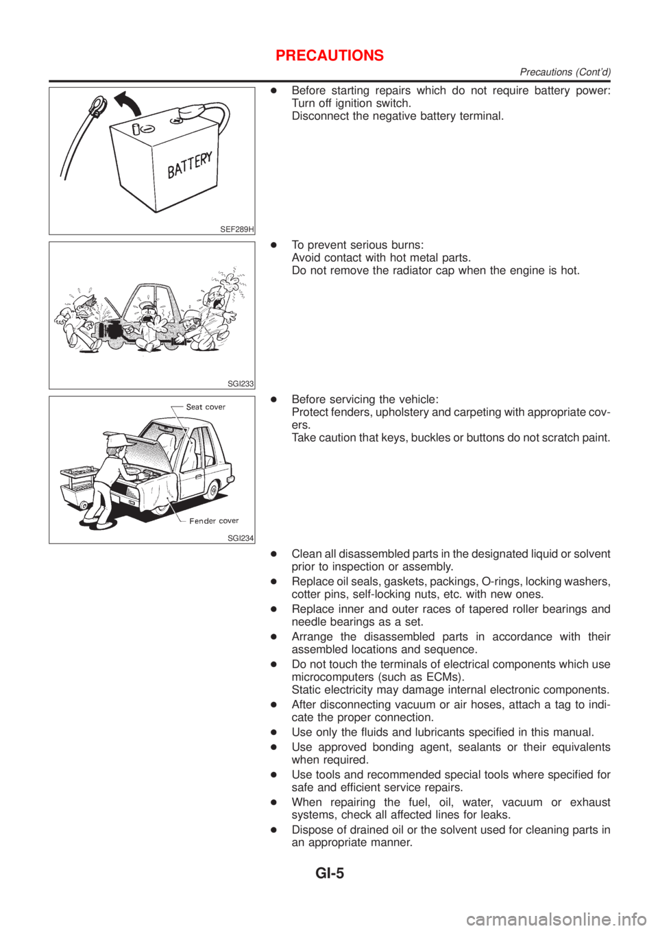
+Before starting repairs which do not require battery power:
Turn off ignition switch.
Disconnect the negative battery terminal.
SGI233
+To prevent serious burns:
Avoid contact with hot metal parts.
Do not remove the radiator cap when the engine is hot.
SGI234
+Before servicing the vehicle:
Protect fenders, upholstery and carpeting with appropriate cov-
ers.
Take caution that keys, buckles or buttons do not scratch paint.
+Clean all disassembled parts in the designated liquid or solvent
prior to inspection or assembly.
+Replace oil seals, gaskets, packings, O-rings, locking washers,
cotter pins, self-locking nuts, etc. with new ones.
+Replace inner and outer races of tapered roller bearings and
needle bearings as a set.
+Arrange the disassembled parts in accordance with their
assembled locations and sequence.
+Do not touch the terminals of electrical components which use
microcomputers (such as ECMs).
Static electricity may damage internal electronic components.
+After disconnecting vacuum or air hoses, attach a tag to indi-
cate the proper connection.
+Use only the fluids and lubricants specified in this manual.
+Use approved bonding agent, sealants or their equivalents
when required.
+Use tools and recommended special tools where specified for
safe and efficient service repairs.
+When repairing the fuel, oil, water, vacuum or exhaust
systems, check all affected lines for leaks.
+Dispose of drained oil or the solvent used for cleaning parts in
an appropriate manner.
PRECAUTIONS
Precautions (Cont'd)
GI-5
Page 219 of 2493
JEM193G
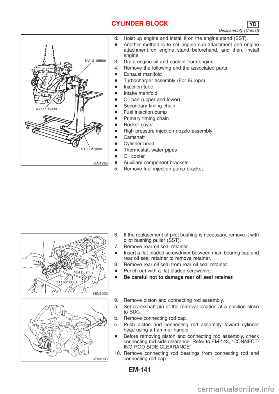
d. Hoist up engine and install it on the engine stand (SST).
+Another method is to set engine sub-attachment and engine
attachment on engine stand beforehand, and then, install
engine.
3. Drain engine oil and coolant from engine.
4. Remove the following and the associated parts:
+Exhaust manifold
+Turbocharger assembly (For Europe)
+Injection tube
+Intake manifold
+Oil pan (upper and lower)
+Secondary timing chain
+Fuel injection pump
+Primary timing chain
+Rocker cover
+High pressure injection nozzle assembly
+Camshaft
+Cylinder head
+Thermostat, water pipes
+Oil cooler
+Auxiliary component brackets
5. Remove fuel injection pump bracket.
SEM500G
6. If the replacement of pilot bushing is necessary, remove it with
pilot bushing puller (SST).
7. Remove rear oil seal retainer.
+Insert a flat-bladed screwdriver between main bearing cap and
rear oil seal retainer to remove retainer.
8. Remove rear oil seal from rear oil seal retainer.
+Punch out with a flat-bladed screwdriver.
+Be careful not to damage rear oil seal retainer.
JEM195G
9. Remove piston and connecting rod assembly.
a. Set crankshaft pin of the removal location at a position close
to BDC.
b. Remove connecting rod cap.
c. Push piston and connecting rod assembly toward cylinder
head using a hammer handle.
+Before removing piston and connecting rod assembly, check
connecting rod side clearance. Refer to EM-143, ªCONNECT-
ING ROD SIDE CLEARANCEº.
10. Remove connecting rod bearings from connecting rod and
connecting rod cap.
CYLINDER BLOCKYD
Disassembly (Cont'd)
EM-141
Page 316 of 2493
Special Service ToolsNJEC0007
Tool number
Tool nameDescription
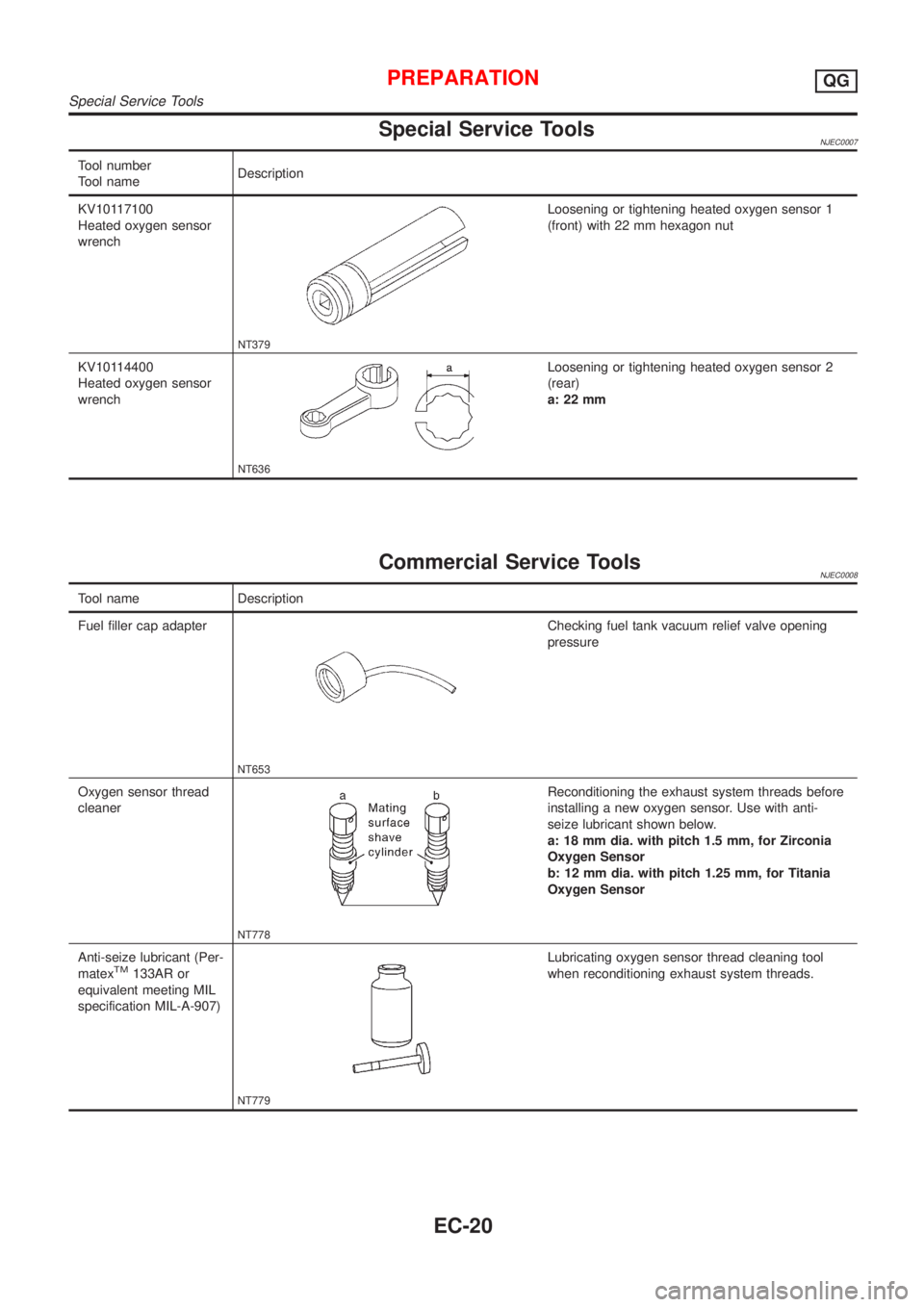
KV10117100
Heated oxygen sensor
wrench
NT379
Loosening or tightening heated oxygen sensor 1
(front) with 22 mm hexagon nut
KV10114400
Heated oxygen sensor
wrench
NT636
Loosening or tightening heated oxygen sensor 2
(rear)
a: 22 mm
Commercial Service ToolsNJEC0008
Tool name Description
Fuel filler cap adapter
NT653
Checking fuel tank vacuum relief valve opening
pressure
Oxygen sensor thread
cleaner
NT778
Reconditioning the exhaust system threads before
installing a new oxygen sensor. Use with anti-
seize lubricant shown below.
a: 18 mm dia. with pitch 1.5 mm, for Zirconia
Oxygen Sensor
b: 12 mm dia. with pitch 1.25 mm, for Titania
Oxygen Sensor
Anti-seize lubricant (Per-
matex
TM133AR or
equivalent meeting MIL
specification MIL-A-907)
NT779
Lubricating oxygen sensor thread cleaning tool
when reconditioning exhaust system threads.
PREPARATIONQG
Special Service Tools
EC-20
Page 330 of 2493
EVAP canister purge volume control solenoid valve is controlled by ECM. When the engine operates, the flow
rate of vapor controlled by EVAP canister purge volume control solenoid valve is proportionally regulated as
the air flow increases.
EVAP canister purge volume control solenoid valve also shuts off the vapor purge line during decelerating and
idling.
SEF917W
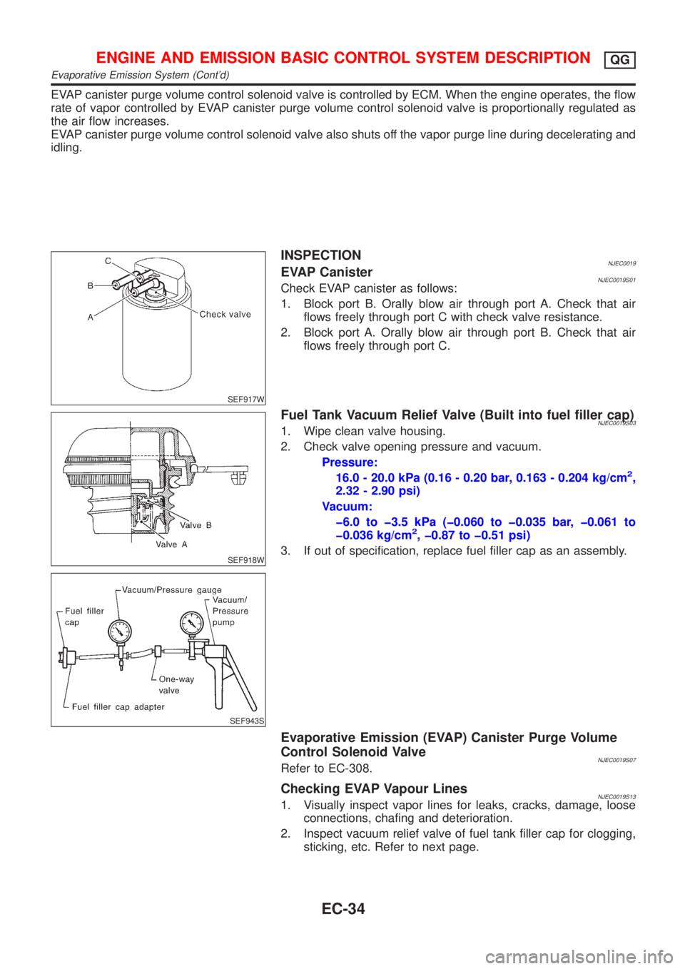
INSPECTIONNJEC0019EVAP CanisterNJEC0019S01Check EVAP canister as follows:
1. Block port B. Orally blow air through port A. Check that air
flows freely through port C with check valve resistance.
2. Block port A. Orally blow air through port B. Check that air
flows freely through port C.
SEF918W
SEF943S
Fuel Tank Vacuum Relief Valve (Built into fuel filler cap)NJEC0019S031. Wipe clean valve housing.
2. Check valve opening pressure and vacuum.
Pressure:
16.0 - 20.0 kPa (0.16 - 0.20 bar, 0.163 - 0.204 kg/cm
2,
2.32 - 2.90 psi)
Vacuum:
þ6.0 to þ3.5 kPa (þ0.060 to þ0.035 bar, þ0.061 to
þ0.036 kg/cm
2, þ0.87 to þ0.51 psi)
3. If out of specification, replace fuel filler cap as an assembly.
Evaporative Emission (EVAP) Canister Purge Volume
Control Solenoid Valve
NJEC0019S07Refer to EC-308.
Checking EVAP Vapour LinesNJEC0019S131. Visually inspect vapor lines for leaks, cracks, damage, loose
connections, chafing and deterioration.
2. Inspect vacuum relief valve of fuel tank filler cap for clogging,
sticking, etc. Refer to next page.
ENGINE AND EMISSION BASIC CONTROL SYSTEM DESCRIPTIONQG
Evaporative Emission System (Cont'd)
EC-34
Page 335 of 2493
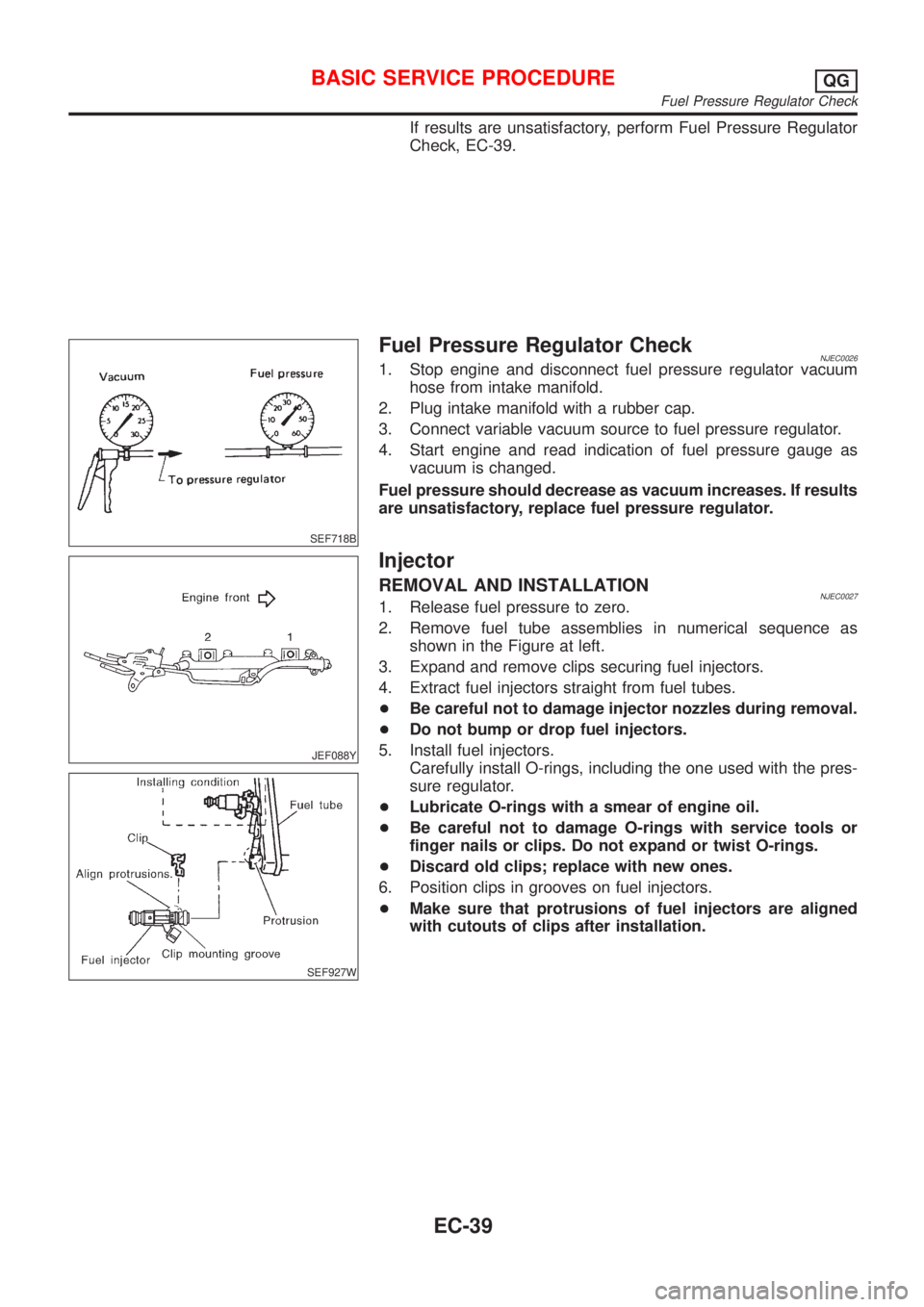
If results are unsatisfactory, perform Fuel Pressure Regulator
Check, EC-39.
SEF718B
Fuel Pressure Regulator CheckNJEC00261. Stop engine and disconnect fuel pressure regulator vacuum
hose from intake manifold.
2. Plug intake manifold with a rubber cap.
3. Connect variable vacuum source to fuel pressure regulator.
4. Start engine and read indication of fuel pressure gauge as
vacuum is changed.
Fuel pressure should decrease as vacuum increases. If results
are unsatisfactory, replace fuel pressure regulator.
JEF088Y
SEF927W
Injector
REMOVAL AND INSTALLATIONNJEC00271. Release fuel pressure to zero.
2. Remove fuel tube assemblies in numerical sequence as
shown in the Figure at left.
3. Expand and remove clips securing fuel injectors.
4. Extract fuel injectors straight from fuel tubes.
+Be careful not to damage injector nozzles during removal.
+Do not bump or drop fuel injectors.
5. Install fuel injectors.
Carefully install O-rings, including the one used with the pres-
sure regulator.
+Lubricate O-rings with a smear of engine oil.
+Be careful not to damage O-rings with service tools or
finger nails or clips. Do not expand or twist O-rings.
+Discard old clips; replace with new ones.
6. Position clips in grooves on fuel injectors.
+Make sure that protrusions of fuel injectors are aligned
with cutouts of clips after installation.
BASIC SERVICE PROCEDUREQG
Fuel Pressure Regulator Check
EC-39
Page 423 of 2493
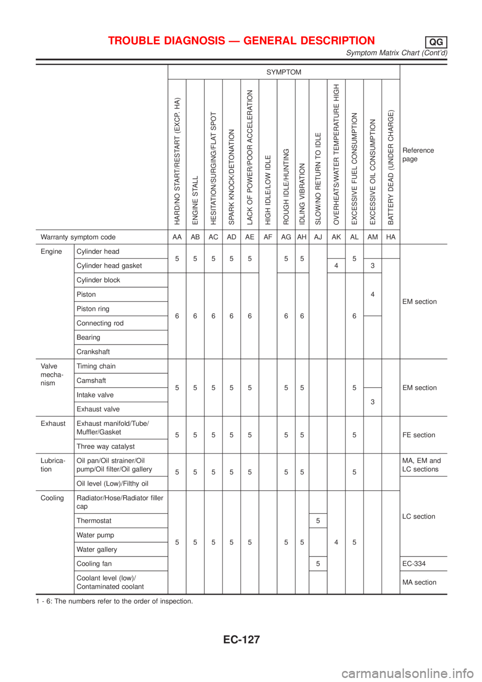
SYMPTOM
Reference
page
HARD/NO START/RESTART (EXCP. HA)
ENGINE STALL
HESITATION/SURGING/FLAT SPOT
SPARK KNOCK/DETONATION
LACK OF POWER/POOR ACCELERATION
HIGH IDLE/LOW IDLE
ROUGH IDLE/HUNTING
IDLING VIBRATION
SLOW/NO RETURN TO IDLE
OVERHEATS/WATER TEMPERATURE HIGH
EXCESSIVE FUEL CONSUMPTION
EXCESSIVE OIL CONSUMPTION
BATTERY DEAD (UNDER CHARGE)
Warranty symptom code AA AB AC AD AE AF AG AH AJ AK AL AM HA
Engine Cylinder head
55555 55 5
EM section Cylinder head gasket 4 3
Cylinder block
66666 66 64 Piston
Piston ring
Connecting rod
Bearing
Crankshaft
Valve
mecha-
nismTiming chain
55555 55 5 EMsection Camshaft
Intake valve
3
Exhaust valve
Exhaust Exhaust manifold/Tube/
Muffler/Gasket
55555 55 5 FEsection
Three way catalyst
Lubrica-
tionOil pan/Oil strainer/Oil
pump/Oil filter/Oil gallery
55555 55 5MA, EM and
LC sections
Oil level (Low)/Filthy oil
LC section Cooling Radiator/Hose/Radiator filler
cap
55555 55 45 Thermostat 5
Water pump
Water gallery
Cooling fan 5 EC-334
Coolant level (low)/
Contaminated coolantMA section
1 - 6: The numbers refer to the order of inspection.
TROUBLE DIAGNOSIS Ð GENERAL DESCRIPTIONQG
Symptom Matrix Chart (Cont'd)
EC-127
Page 510 of 2493
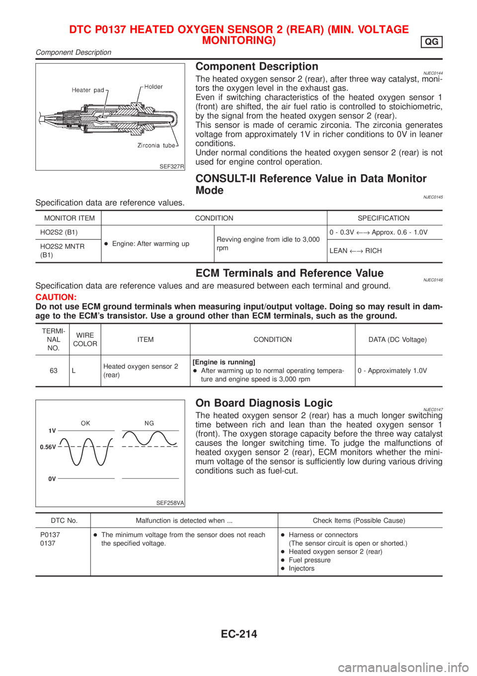
SEF327R
Component DescriptionNJEC0144The heated oxygen sensor 2 (rear), after three way catalyst, moni-
tors the oxygen level in the exhaust gas.
Even if switching characteristics of the heated oxygen sensor 1
(front) are shifted, the air fuel ratio is controlled to stoichiometric,
by the signal from the heated oxygen sensor 2 (rear).
This sensor is made of ceramic zirconia. The zirconia generates
voltage from approximately 1V in richer conditions to 0V in leaner
conditions.
Under normal conditions the heated oxygen sensor 2 (rear) is not
used for engine control operation.
CONSULT-II Reference Value in Data Monitor
Mode
NJEC0145Specification data are reference values.
MONITOR ITEM CONDITION SPECIFICATION
HO2S2 (B1)
+Engine: After warming upRevving engine from idle to 3,000
rpm0 - 0.3V¨Approx. 0.6 - 1.0V
HO2S2 MNTR
(B1)LEAN¨RICH
ECM Terminals and Reference ValueNJEC0146Specification data are reference values and are measured between each terminal and ground.
CAUTION:
Do not use ECM ground terminals when measuring input/output voltage. Doing so may result in dam-
age to the ECM's transistor. Use a ground other than ECM terminals, such as the ground.
TERMI-
NAL
NO.WIRE
COLORITEM CONDITION DATA (DC Voltage)
63 LHeated oxygen sensor 2
(rear)[Engine is running]
+After warming up to normal operating tempera-
ture and engine speed is 3,000 rpm0 - Approximately 1.0V
SEF258VA
On Board Diagnosis LogicNJEC0147The heated oxygen sensor 2 (rear) has a much longer switching
time between rich and lean than the heated oxygen sensor 1
(front). The oxygen storage capacity before the three way catalyst
causes the longer switching time. To judge the malfunctions of
heated oxygen sensor 2 (rear), ECM monitors whether the mini-
mum voltage of the sensor is sufficiently low during various driving
conditions such as fuel-cut.
DTC No. Malfunction is detected when ... Check Items (Possible Cause)
P0137
0137+The minimum voltage from the sensor does not reach
the specified voltage.+Harness or connectors
(The sensor circuit is open or shorted.)
+Heated oxygen sensor 2 (rear)
+Fuel pressure
+Injectors
DTC P0137 HEATED OXYGEN SENSOR 2 (REAR) (MIN. VOLTAGE
MONITORING)
QG
Component Description
EC-214
Page 518 of 2493

SEF327R
Component DescriptionNJEC0153The heated oxygen sensor 2 (rear), after three way catalyst, moni-
tors the oxygen level in the exhaust gas.
Even if switching characteristics of the heated oxygen sensor 1
(front) are shifted, the air fuel ratio is controlled to stoichiometric,
by the signal from the heated oxygen sensor 2 (rear).
This sensor is made of ceramic zirconia. The zirconia generates
voltage from approximately 1V in richer conditions to 0V in leaner
conditions.
Under normal conditions the heated oxygen sensor 2 (rear) is not
used for engine control operation.
CONSULT-II Reference Value in Data Monitor
Mode
NJEC0154Specification data are reference values.
MONITOR ITEM CONDITION SPECIFICATION
HO2S2 (B1)
+Engine: After warming upRevving engine from idle to 3,000
rpm0 - 0.3V¨Approx. 0.6 - 1.0V
HO2S2 MNTR
(B1)LEAN¨RICH
ECM Terminals and Reference ValueNJEC0155Specification data are reference values and are measured between each terminal and ground.
CAUTION:
Do not use ECM ground terminals when measuring input/output voltage. Doing so may result in dam-
age to the ECM's transistor. Use a ground other than ECM terminals, such as the ground.
TERMI-
NAL
NO.WIRE
COLORITEM CONDITION DATA (DC Voltage)
63 LHeated oxygen sensor 2
(rear)[Engine is running]
+After warming up to normal operating tempera-
ture and engine speed is 2,000 rpm0 - Approximately 1.0V
SEF259VA
On Board Diagnosis LogicNJEC0156The heated oxygen sensor 2 (rear) has a much longer switching
time between rich and lean than the heated oxygen sensor 1
(front). The oxygen storage capacity before the three way catalyst
causes the longer switching time. To judge the malfunctions of
heated oxygen sensor 2 (rear), ECM monitors whether the maxi-
mum voltage of the sensor is sufficiently high during various driv-
ing conditions such as fuel-cut.
DTC No. Malfunction is detected when ... Check Items (Possible Cause)
P0138
0138+The maximum voltage from the sensor does not reach
the specified voltage.+Harness or connectors
(The sensor circuit is open or shorted.)
+Heated oxygen sensor 2 (rear)
+Fuel pressure
+Injectors
+Intake air leaks
DTC P0138 HEATED OXYGEN SENSOR 2 (REAR) (MAX. VOLTAGE
MONITORING)
QG
Component Description
EC-222