2001 NISSAN ALMERA N16 Power window
[x] Cancel search: Power windowPage 58 of 2493

NJMA0036
Shown below are Pre-delivery Inspection Items required for the new vehicle. It is recommended that
necessary items other than those listed here be added, paying due regard to the conditions in each
country.
Perform applicable items on each model. Consult text of this section for specifications.
UNDER HOOD Ð engine off
Radiator coolant level and coolant hose connections for leaks
Battery fluid level, specific gravity and conditions of battery terminals
Drive belts tension
Fuel filter for water or dusts (Diesel only), and fuel lines and connections for leaks
Engine oil level and oil leaks
Clutch and brake reservoir fluid level and fluid lines for leaks
Windshield and rear window washer and headlamp cleaner reservoir fluid level
Power steering reservoir fluid level and hose connections for leaks
ON INSIDE AND OUTSIDE
Remove front spring/strut spacer (If applicable)
Operation of all instruments, gauges, lights and accessories
Operation of horn(s), wiper and washer
Steering lock for operation
Check air conditioner for gas leaks
Front and rear seats, and seat belts for operation
All moldings, trims and fittings for fit and alignment
All windows for operation and alignment
Hood, trunk lid, door panels for fit and alignment
Latches, keys and locks for operation
Weatherstrips for adhesion and fit
Headlamp aiming
Tighten wheel nuts (Inc. inner nuts if applicable)
Tire pressure (Inc. spare tire)
Check front wheels for toe-in
Install clock/voltmeter/room lamp fuse (If applicable)
Install deodorizing filter to air conditioner (If applicable)
Remove wiper blade protectors (If applicable)
UNDER BODY
Manual transmission/transaxle, transfer and differential gear oil level
Brake and fuel lines and oil/fluid reservoirs for leaks
Tighten bolts and nuts of steering linkage and gear box, suspension, propeller shafts and drive shafts
Tighten rear body bolts and nuts (Models with wooden bed only)
ROAD TEST
Clutch operation
Parking brake operation
Service brake operation
Automatic transmission/transaxle shift timing and kickdown
Steering control and returnability
Engine performance
Squeaks and rattles
ENGINE OPERATING AND HOT
Adjust idle speed
Automatic transmission/transaxle fluid level
Engine idling and stop knob operation (Diesel only)
FINAL INSPECTION
Install necessary parts (outside mirror, wheel covers, seat belts, mat, carpet or mud flaps)
Inspect for interior and exterior metal and paint damage
Check for spare tire, jack, tools (wheel chock), and literature
Wash, clean interior and exterior
: Not applicable to this model
PRE-DELIVERY INSPECTION ITEMS
MA-2
Page 781 of 2493
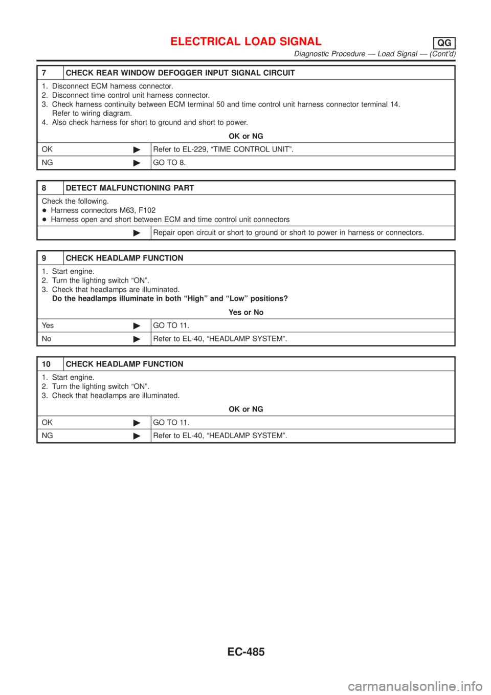
7 CHECK REAR WINDOW DEFOGGER INPUT SIGNAL CIRCUIT
1. Disconnect ECM harness connector.
2. Disconnect time control unit harness connector.
3. Check harness continuity between ECM terminal 50 and time control unit harness connector terminal 14.
Refer to wiring diagram.
4. Also check harness for short to ground and short to power.
OK or NG
OK©Refer to EL-229, ªTIME CONTROL UNITº.
NG©GO TO 8.
8 DETECT MALFUNCTIONING PART
Check the following.
+Harness connectors M63, F102
+Harness open and short between ECM and time control unit connectors
©Repair open circuit or short to ground or short to power in harness or connectors.
9 CHECK HEADLAMP FUNCTION
1. Start engine.
2. Turn the lighting switch ªONº.
3. Check that headlamps are illuminated.
Do the headlamps illuminate in both ªHighº and ªLowº positions?
YesorNo
Ye s©GO TO 11.
No©Refer to EL-40, ªHEADLAMP SYSTEMº.
10 CHECK HEADLAMP FUNCTION
1. Start engine.
2. Turn the lighting switch ªONº.
3. Check that headlamps are illuminated.
OK or NG
OK©GO TO 11.
NG©Refer to EL-40, ªHEADLAMP SYSTEMº.
ELECTRICAL LOAD SIGNALQG
Diagnostic Procedure Ð Load Signal Ð (Cont'd)
EC-485
Page 1911 of 2493
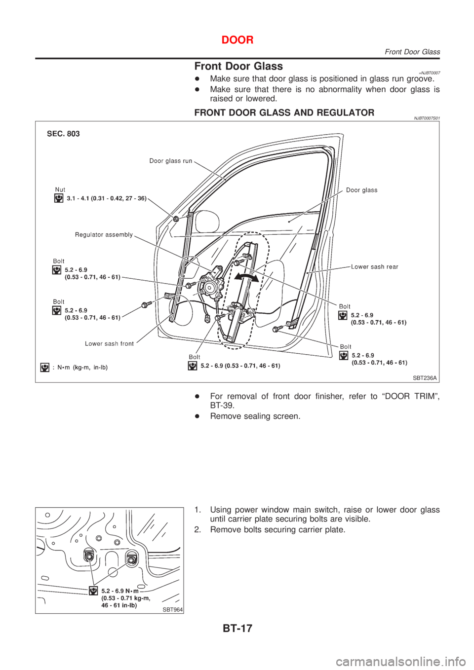
Front Door Glass=NJBT0007+Make sure that door glass is positioned in glass run groove.
+Make sure that there is no abnormality when door glass is
raised or lowered.
FRONT DOOR GLASS AND REGULATORNJBT0007S01
SBT236A
+For removal of front door finisher, refer to ªDOOR TRIMº,
BT-39.
+Remove sealing screen.
SBT964
1. Using power window main switch, raise or lower door glass
until carrier plate securing bolts are visible.
2. Remove bolts securing carrier plate.
DOOR
Front Door Glass
BT-17
Page 1913 of 2493
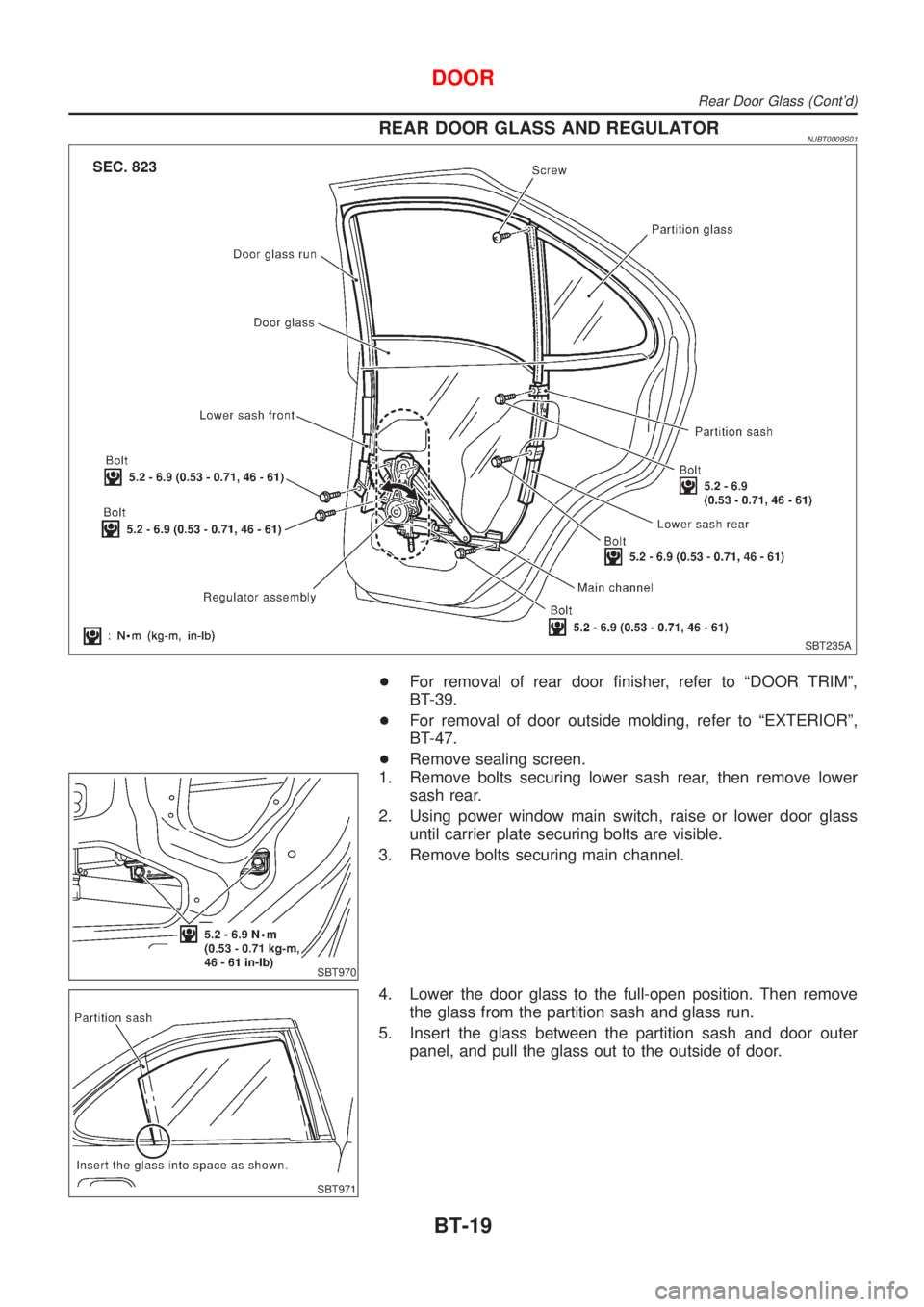
REAR DOOR GLASS AND REGULATORNJBT0009S01
SBT235A
+For removal of rear door finisher, refer to ªDOOR TRIMº,
BT-39.
+For removal of door outside molding, refer to ªEXTERIORº,
BT-47.
+Remove sealing screen.
SBT970
1. Remove bolts securing lower sash rear, then remove lower
sash rear.
2. Using power window main switch, raise or lower door glass
until carrier plate securing bolts are visible.
3. Remove bolts securing main channel.
SBT971
4. Lower the door glass to the full-open position. Then remove
the glass from the partition sash and glass run.
5. Insert the glass between the partition sash and door outer
panel, and pull the glass out to the outside of door.
DOOR
Rear Door Glass (Cont'd)
BT-19
Page 1933 of 2493
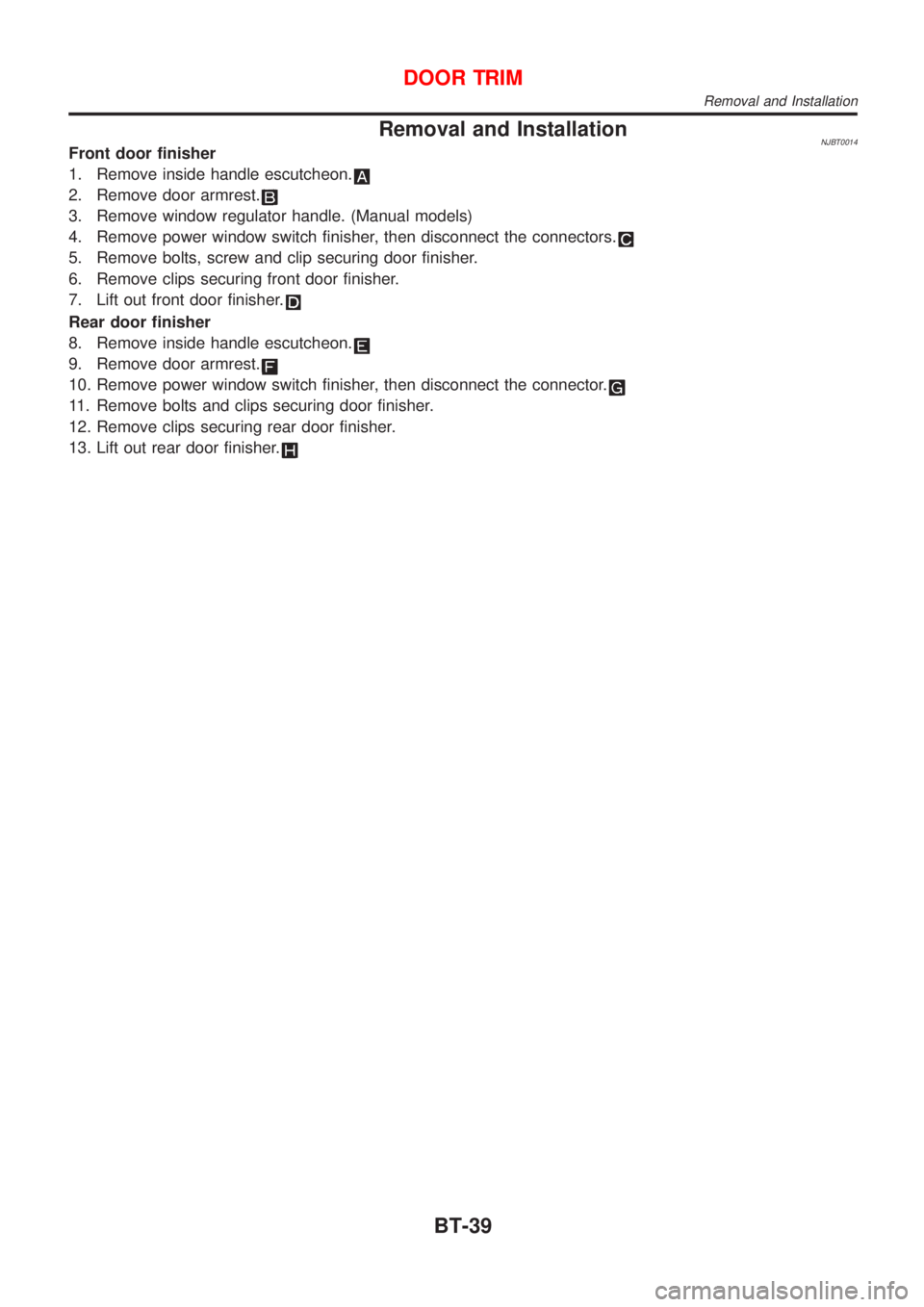
Removal and InstallationNJBT0014Front door finisher
1. Remove inside handle escutcheon.
2. Remove door armrest.
3. Remove window regulator handle. (Manual models)
4. Remove power window switch finisher, then disconnect the connectors.
5. Remove bolts, screw and clip securing door finisher.
6. Remove clips securing front door finisher.
7. Lift out front door finisher.
Rear door finisher
8. Remove inside handle escutcheon.
9. Remove door armrest.
10. Remove power window switch finisher, then disconnect the connector.
11. Remove bolts and clips securing door finisher.
12. Remove clips securing rear door finisher.
13. Lift out rear door finisher.
DOOR TRIM
Removal and Installation
BT-39
Page 1962 of 2493
SBF034BA
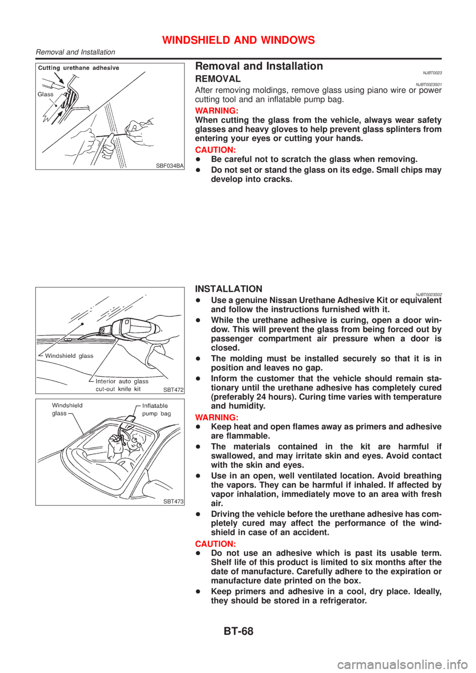
Removal and InstallationNJBT0023REMOVALNJBT0023S01After removing moldings, remove glass using piano wire or power
cutting tool and an inflatable pump bag.
WARNING:
When cutting the glass from the vehicle, always wear safety
glasses and heavy gloves to help prevent glass splinters from
entering your eyes or cutting your hands.
CAUTION:
+Be careful not to scratch the glass when removing.
+Do not set or stand the glass on its edge. Small chips may
develop into cracks.
SBT472
SBT473
INSTALLATIONNJBT0023S02+Use a genuine Nissan Urethane Adhesive Kit or equivalent
and follow the instructions furnished with it.
+While the urethane adhesive is curing, open a door win-
dow. This will prevent the glass from being forced out by
passenger compartment air pressure when a door is
closed.
+The molding must be installed securely so that it is in
position and leaves no gap.
+Inform the customer that the vehicle should remain sta-
tionary until the urethane adhesive has completely cured
(preferably 24 hours). Curing time varies with temperature
and humidity.
WARNING:
+Keep heat and open flames away as primers and adhesive
are flammable.
+The materials contained in the kit are harmful if
swallowed, and may irritate skin and eyes. Avoid contact
with the skin and eyes.
+Use in an open, well ventilated location. Avoid breathing
the vapors. They can be harmful if inhaled. If affected by
vapor inhalation, immediately move to an area with fresh
air.
+Driving the vehicle before the urethane adhesive has com-
pletely cured may affect the performance of the wind-
shield in case of an accident.
CAUTION:
+Do not use an adhesive which is past its usable term.
Shelf life of this product is limited to six months after the
date of manufacture. Carefully adhere to the expiration or
manufacture date printed on the box.
+Keep primers and adhesive in a cool, dry place. Ideally,
they should be stored in a refrigerator.
WINDSHIELD AND WINDOWS
Removal and Installation
BT-68
Page 2114 of 2493
WARNING CHIME....................................................... 113
Component Parts and Harness Connector
Location ................................................................... 113
System Description .................................................. 113
Wiring Diagram - CHIME - ...................................... 115
Trouble Diagnoses................................................... 117
FRONT WIPER AND WASHER..................................123
System Description ..................................................123
Wiring Diagram - WIPER - ......................................125
Removal and Installation .........................................127
Washer Nozzle Adjustment .....................................128
Washer Tube Layout ...............................................128
REAR WIPER AND WASHER....................................129
Wiring Diagram - WIP/R -........................................129
Removal and Installation .........................................131
Washer Nozzle Adjustment .....................................131
Washer Tube Layout ...............................................132
HEADLAMP WASHER................................................133
Wiring Diagram - HLC - ...........................................133
Washer Tube Layout ...............................................134
HORN...........................................................................135
Wiring Diagram - HORN - .......................................135
CIGARETTE LIGHTER................................................136
Wiring Diagram - CIGAR -.......................................136
CLOCK.........................................................................137
Wiring Diagram - CLOCK -......................................137
REAR WINDOW DEFOGGER.....................................138
System Description ..................................................138
Schematic ................................................................139
Wiring Diagram - DEF - ...........................................140
Trouble Diagnoses...................................................143
Electrical Components Inspection ...........................146
Filament Check ........................................................147
Filament Repair .......................................................148
AUDIO..........................................................................149
System Description ..................................................149
Schematic ................................................................151
Wiring Diagram - AUDIO - .......................................152
Trouble Diagnoses...................................................160
Inspection.................................................................161
AUDIO ANTENNA.......................................................162
Location of Antenna .................................................162
Antenna Rod Replacement .....................................162
HEATED SEAT............................................................163
Wiring Diagram - H/SEAT - .....................................163
POWER SUNROOF.....................................................165
Wiring Diagram - SROOF - .....................................165
Trouble Diagnoses...................................................166
DOOR MIRROR...........................................................167
Wiring Diagram - MIRROR - ...................................167
POWER WINDOW.......................................................169
System Description ..................................................169Schematic ................................................................171
Wiring Diagram - WINDOW - ..................................172
Trouble Diagnoses...................................................176
POWER DOOR LOCK.................................................177
System Description ..................................................177
Schematic ................................................................178
Wiring Diagram - D/LOCK -.....................................180
Trouble Diagnoses...................................................187
POWER DOOR LOCK - SUPER LOCK -...................196
System Description ..................................................196
Schematic ................................................................198
Wiring Diagram - S/LOCK - .....................................200
Trouble Diagnoses...................................................207
MULTI-REMOTE CONTROL SYSTEM.......................220
System Description ..................................................220
Wiring Diagram - MULTI - .......................................221
Trouble Diagnoses...................................................223
ID Code Entry Procedure ........................................227
Remote Controller Battery Replacement.................228
TIME CONTROL UNIT................................................229
Description ...............................................................229
Trouble Diagnoses...................................................230
Schematic ................................................................232
NATS (NISSAN ANTI-THEFT SYSTEM).....................234
Component Parts and Harness Connetor
Location ...................................................................234
System Description ..................................................234
System Composition ................................................236
Wiring Diagram - NATS -.........................................237
CONSULT-II .............................................................238
Trouble Diagnoses...................................................241
How to Replace NATS IMMU ..................................258
NAVIGATION SYSTEM...............................................259
Precautions ..............................................................259
Component Parts Location ......................................260
System Description ..................................................261
Schematic ................................................................269
Wiring Diagram - NAVI - ..........................................270
Self-diagnosis Mode ................................................278
Confirmation/Adjustment Mode ...............................281
Control Panel Mode .................................................293
Guide Volume Setting ..............................................300
Anti-theft System .....................................................301
CONSULT-II .............................................................302
Trouble Diagnoses...................................................303
This Condition Is Not Abnormal...............................309
Program Loading .....................................................318
ELECTRICAL UNITS LOCATION...............................319
Engine Compartment ...............................................319
Passenger Compartment/LHD Models ....................320
Passenger Compartment/RHD Models ...................322
CONTENTS(Cont'd)
EL-2
Page 2250 of 2493
System Description=NJEL0463The rear window defogger system is controlled by the time control unit. The rear window defogger operates
only for approximately 15 minutes.
Power is supplied at all times
+through 20A fuse [No. 7, located in the fuse block (J/B)]
+to rear window defogger relay terminal 5 (B7 relay models) or 3 (B6 relay models)
+through 10A fuse [No. 13, located in the fuse block (J/B)]
+to rear window defogger relay terminal 6 (B6 relay models).
+through 15A fuse [No. 5, located in the fuse block (J/B)]
+to time control unit terminal 9.
With the ignition switch in the ON or START position, power is supplied
+through 10A fuse [No. 10, located in the fuse block (J/B)]
+to the rear window defogger relay terminal 1 and
+to time control unit terminal 1.
Ground is supplied to terminal 5 of the rear window defogger switch through body grounds M28 and M67.
When the rear defogger switch is turned ON, ground is supplied
+through terminal 3 of the rear defogger switch
+to time control unit terminal 3.
Terminal 13 of time control unit then supplies ground to the rear window defogger relay terminal 2.
With power and ground supplied, the rear window defogger relay is energized.
Power is supplied
+through terminals 5 and 7 of the rear window defogger relay (B6 relay models) or
+through terminal 3 of the rear window defogger relay (B7 relay models)
+to the rear window defogger and door mirror defogger.
The rear window defogger has an independent ground.
With power and ground supplied, the rear window defogger filaments heat and defog the rear window.
When the system is activated, the rear window defogger indicator illuminates in the rear window defogger
switch.
REAR WINDOW DEFOGGER
System Description
EL-138