2001 NISSAN ALMERA N16 parking brake
[x] Cancel search: parking brakePage 19 of 2493

AGI070
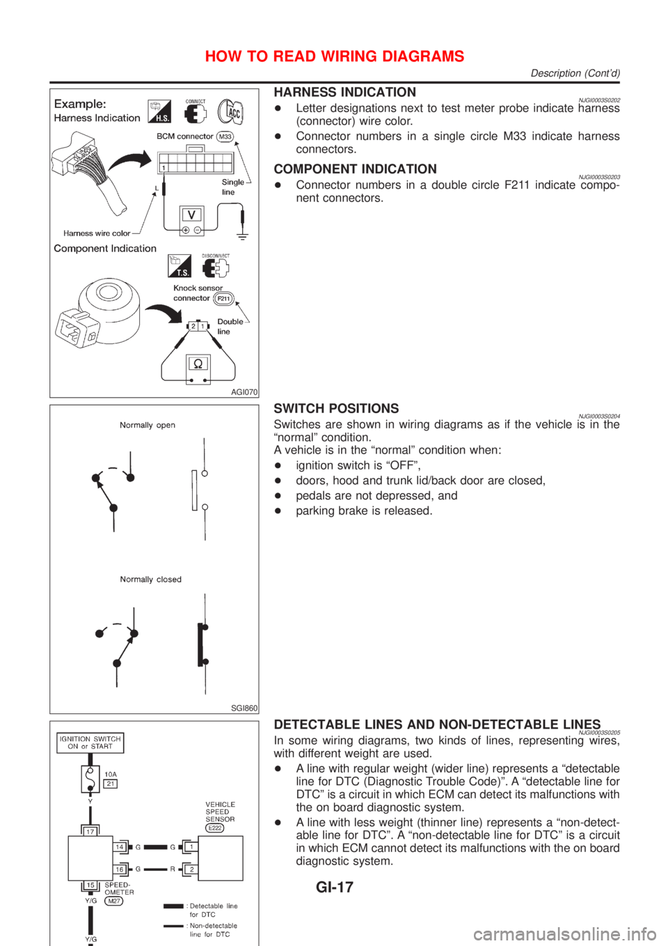
HARNESS INDICATIONNJGI0003S0202+Letter designations next to test meter probe indicate harness
(connector) wire color.
+Connector numbers in a single circle M33 indicate harness
connectors.
COMPONENT INDICATIONNJGI0003S0203+Connector numbers in a double circle F211 indicate compo-
nent connectors.
SGI860
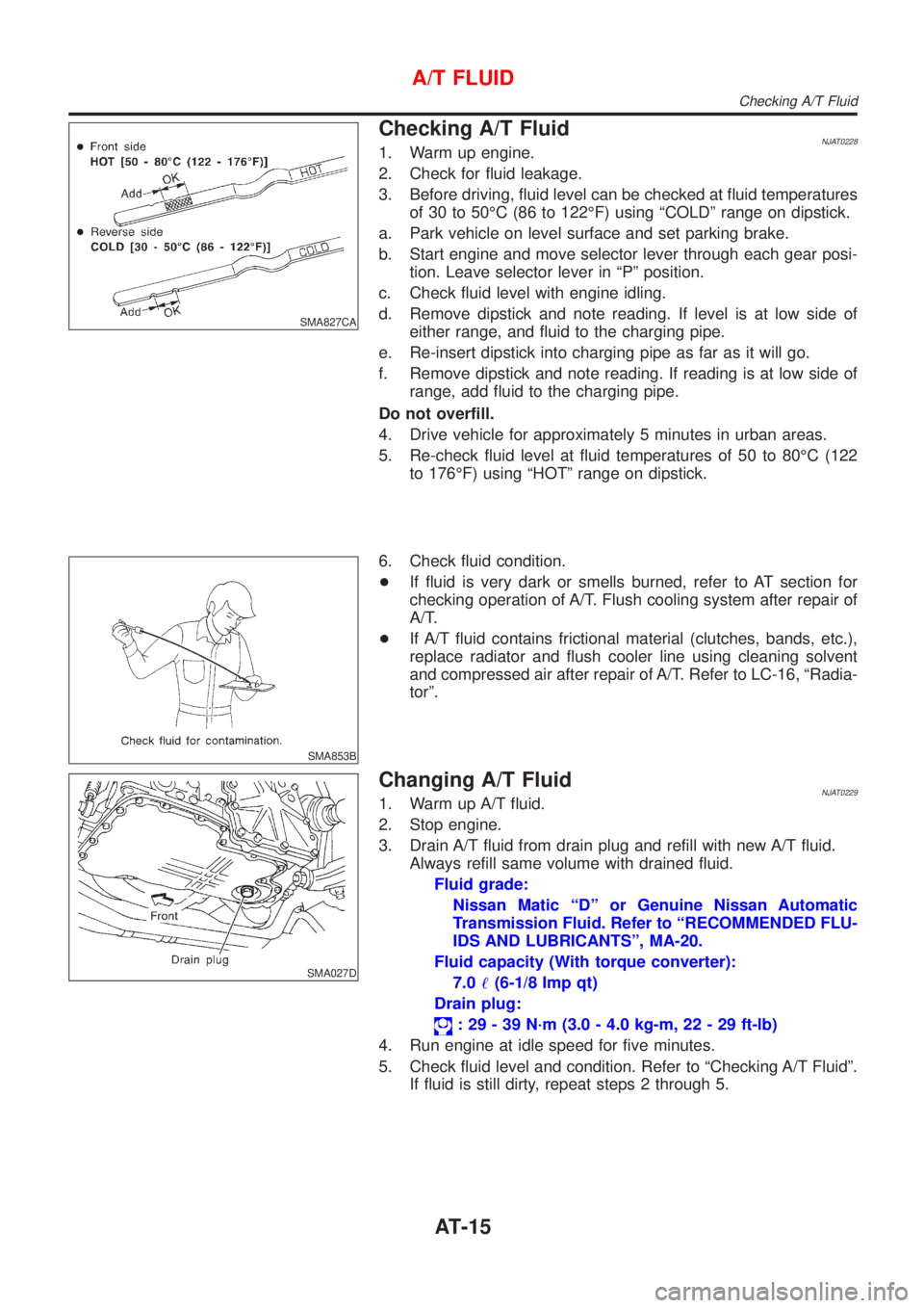
SWITCH POSITIONSNJGI0003S0204Switches are shown in wiring diagrams as if the vehicle is in the
ªnormalº condition.
A vehicle is in the ªnormalº condition when:
+ignition switch is ªOFFº,
+doors, hood and trunk lid/back door are closed,
+pedals are not depressed, and
+parking brake is released.
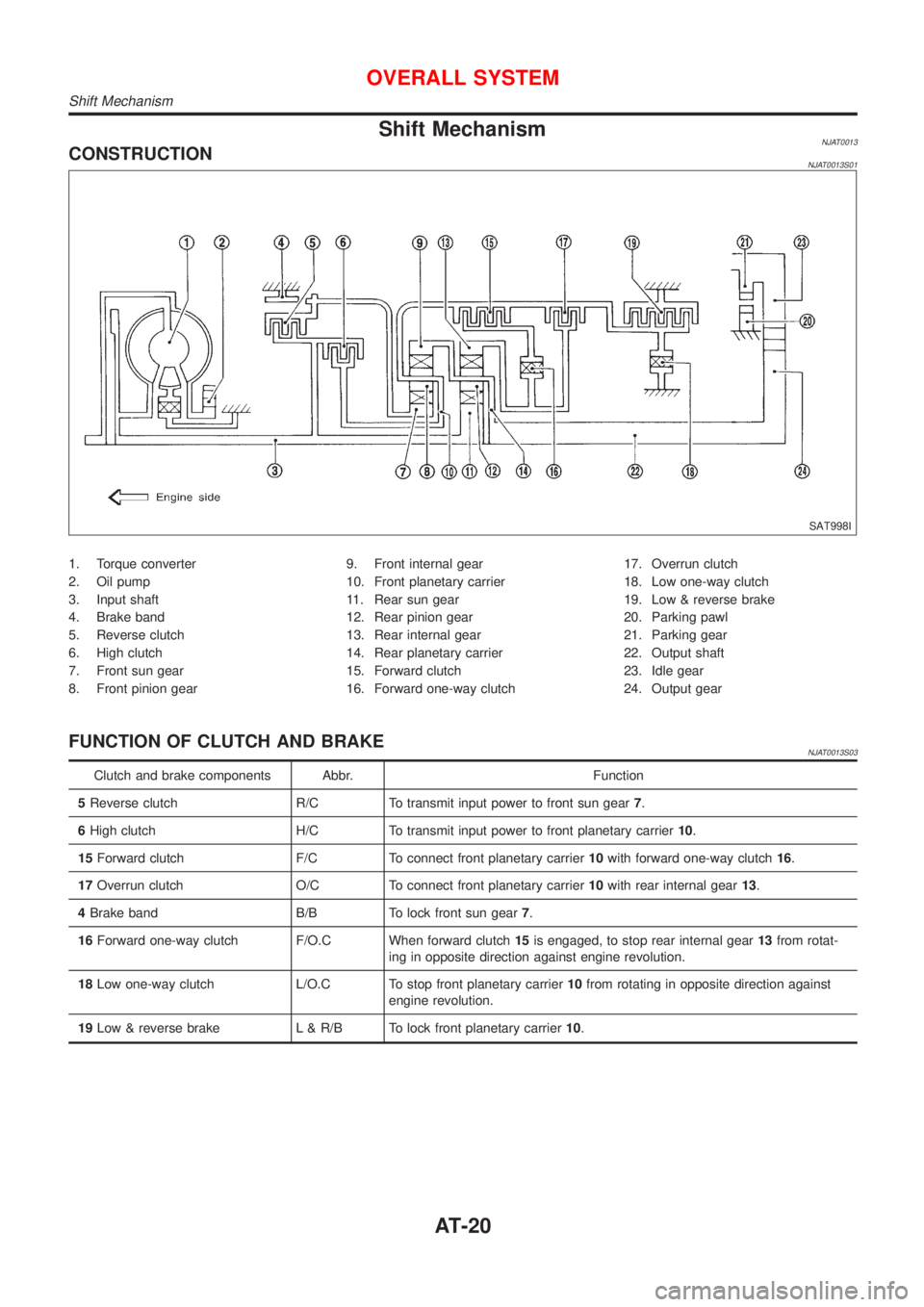
DETECTABLE LINES AND NON-DETECTABLE LINESNJGI0003S0205In some wiring diagrams, two kinds of lines, representing wires,
with different weight are used.
+A line with regular weight (wider line) represents a ªdetectable
line for DTC (Diagnostic Trouble Code)º. A ªdetectable line for
DTCº is a circuit in which ECM can detect its malfunctions with
the on board diagnostic system.
+A line with less weight (thinner line) represents a ªnon-detect-
able line for DTCº. A ªnon-detectable line for DTCº is a circuit
in which ECM cannot detect its malfunctions with the on board
diagnostic system.
HOW TO READ WIRING DIAGRAMS
Description (Cont'd)
GI-17
Page 35 of 2493

Key to Symbols Signifying Measurements or
Procedures
NJGI0006S02
Symbol Symbol explanation Symbol Symbol explanation
Check after disconnecting the con-
nector to be measured.Procedure with Generic Scan Tool
(GST, OBD-II scan tool)
Check after connecting the connec-
tor to be measured.Procedure without CONSULT-II or
GST
Insert key into ignition switch.A/C switch is ªOFFº.
Remove key from ignition switch.A/C switch is ªONº.
Turn ignition switch to ªOFFº posi-
tion.REC switch is ªONº.
Turn ignition switch to ªONº position.REC switch is ªOFFº.
Turn ignition switch to ªSTARTº posi-
tion.Fan switch is ªONº. (At any position
except for ªOFFº position)
Turn ignition switch from ªOFFº to
ªACCº position.Fan switch is ªOFFº.
Turn ignition switch from ªACCº to
ªOFFº position.Apply positive voltage from battery
with fuse directly to components.
Turn ignition switch from ªOFFº to
ªONº position.Drive vehicle.
Turn ignition switch from ªONº to
ªOFFº position.Disconnect battery negative cable.
Do not start engine, or check with
engine stopped.Depress brake pedal.
Start engine, or check with engine
running.Release brake pedal.
Apply parking brake.Depress accelerator pedal.
Release parking brake.Release accelerator pedal.
HOW TO FOLLOW TROUBLE DIAGNOSES
Key to Symbols Signifying Measurements or Procedures
GI-33
Page 58 of 2493

NJMA0036
Shown below are Pre-delivery Inspection Items required for the new vehicle. It is recommended that
necessary items other than those listed here be added, paying due regard to the conditions in each
country.
Perform applicable items on each model. Consult text of this section for specifications.
UNDER HOOD Ð engine off
Radiator coolant level and coolant hose connections for leaks
Battery fluid level, specific gravity and conditions of battery terminals
Drive belts tension
Fuel filter for water or dusts (Diesel only), and fuel lines and connections for leaks
Engine oil level and oil leaks
Clutch and brake reservoir fluid level and fluid lines for leaks
Windshield and rear window washer and headlamp cleaner reservoir fluid level
Power steering reservoir fluid level and hose connections for leaks
ON INSIDE AND OUTSIDE
Remove front spring/strut spacer (If applicable)
Operation of all instruments, gauges, lights and accessories
Operation of horn(s), wiper and washer
Steering lock for operation
Check air conditioner for gas leaks
Front and rear seats, and seat belts for operation
All moldings, trims and fittings for fit and alignment
All windows for operation and alignment
Hood, trunk lid, door panels for fit and alignment
Latches, keys and locks for operation
Weatherstrips for adhesion and fit
Headlamp aiming
Tighten wheel nuts (Inc. inner nuts if applicable)
Tire pressure (Inc. spare tire)
Check front wheels for toe-in
Install clock/voltmeter/room lamp fuse (If applicable)
Install deodorizing filter to air conditioner (If applicable)
Remove wiper blade protectors (If applicable)
UNDER BODY
Manual transmission/transaxle, transfer and differential gear oil level
Brake and fuel lines and oil/fluid reservoirs for leaks
Tighten bolts and nuts of steering linkage and gear box, suspension, propeller shafts and drive shafts
Tighten rear body bolts and nuts (Models with wooden bed only)
ROAD TEST
Clutch operation
Parking brake operation
Service brake operation
Automatic transmission/transaxle shift timing and kickdown
Steering control and returnability
Engine performance
Squeaks and rattles
ENGINE OPERATING AND HOT
Adjust idle speed
Automatic transmission/transaxle fluid level
Engine idling and stop knob operation (Diesel only)
FINAL INSPECTION
Install necessary parts (outside mirror, wheel covers, seat belts, mat, carpet or mud flaps)
Inspect for interior and exterior metal and paint damage
Check for spare tire, jack, tools (wheel chock), and literature
Wash, clean interior and exterior
: Not applicable to this model
PRE-DELIVERY INSPECTION ITEMS
MA-2
Page 59 of 2493

NJMA0004
General maintenance includes those items which should be checked during the normal day-to-day operation
of the vehicle. They are essential if the vehicle is to continue operating properly. The owners can perform the
checks and inspections themselves or they can have their NISSAN dealers do them for a nominal charge.
OUTSIDE THE VEHICLE
The maintenance items listed here should be performed from time to time, unless otherwise specified.
Item Reference page
TiresCheck the pressure with a gauge periodically when at a service station,
including the spare, and adjust to the specified pressure if necessary. Check
carefully for damage, cuts or excessive wear.Ð
Windshield wiper
bladesCheck for cracks or wear if not functioning correctly. Ð
Doors and engine
hoodCheck that all doors, the engine hood, the trunk lid and back door operate
properly. Also ensure that all latches lock securely. Lubricate if necessary.
Make sure that the secondary latch keeps the hood from opening when the
primary latch is released.
When driving in areas using road salt or other corrosive materials, check for
lubrication frequently.BT-7
BT-16
Tire rotationTires should be rotated every 10,000 km (6,000 miles). SU-7
INSIDE THE VEHICLE
The maintenance items listed here should be checked on a regular basis, such as when performing periodic maintenance, cleaning the
vehicle, etc.
Item Reference page
LampsMake sure that the headlamps, stop lamps, tail lamps, turn signal lamps,
and other lamps are all operating properly and installed securely. Also check
headlamp aim.Ð
Warning lamps and
chimesMake sure that all warning lamps and buzzers/chimes are operating prop-
erly.Ð
Steering wheelCheck that it has the specified play.
Check for changes in the steering conditions, such as excessive free play,
hard steering or strange noises.
Free play: Less than 35 mm (1.38 in)Ð
Seat beltsCheck that all parts of the seat belt system (e.g. buckles, anchors, adjusters
and retractors) operate properly and smoothly, and are installed securely.
Check the belt webbing for cuts, fraying, wear or damage.RS-4
UNDER THE HOOD AND VEHICLE
The maintenance items listed here should be checked periodically e.g. each time you check the engine oil or refuel.
Item Reference page
Windshield washer
fluidCheck that there is adequate fluid in the tank. Ð
Engine coolant levelCheck the coolant level when the engine is cold. LC-18, LC-43
Engine oil levelCheck the level after parking the vehicle (on level ground) and turning off
the engine.LC-8, LC-30
Brake and clutch
fluid levelsMake sure that the brake and clutch fluid levels are between the ªMAXº and
ªMINº lines on the reservoir.BR-7
BatteryCheck the fluid level in each cell. It should be between the ªMAXº and ªMINº
lines.Ð
GENERAL MAINTENANCE
MA-3
Page 62 of 2493

Chassis and Body MaintenanceNJMA0005S05Abbreviations: I = Inspect and correct or replace as necessary, R = Replace, L = Lubricate.
MAINTENANCE OPERATIONMAINTENANCE INTERVAL
Reference page Perform either at number of kilome-
ters (miles) or months, whichever
comes first.km x 1,000
(Miles x 1,000)
Months1
(0.6)
Ð10
(6)
620
(12)
1230
(18)
1840
(24)
2450
(30)
3060
(36)
3670
(42)
4280
(48)
48
Underhood and under vehicle
Brake, clutch & automatic transaxle
fluid (For level & leaks)HIIIIIIIIBR-7, AT-78
Brake fluidHR R BR-18
Brake booster vacuum hoses, con-
nections & check valveI I BR-22
Power steering fluid & lines (For
level & leaks)I*1 I I*1 I I*1 I I*1 I ST-7
Brake, clutch & exhaust systemsIIIIIIIIBR-7, FE-11,
FE-27
Manual transaxle gear oil (For level
& leaks)I*1 I I*1 I I*1 I I*1 I MT-15, MT-14
Steering gear & linkage, axle & sus-
pension parts & drive shaftsHI*2IIIIST-7,SU-6, SU-7
Outside and inside
Wheel alignment (If necessary,
rotate & balance wheels)IIIISU-7, SU-14
Brake pads, rotors & other brake
componentsHIIIIIIIIBR-27, BR-35
Brake linings, drums & other brake
componentsHIIIIBR-33
Lock, hinges & hood latchHL*1 L L*1 L L*1 L L*1 L BT-7, BT-16
Seat belts, buckles, retractors,
anchors & adjusterIIIIRS-4
Foot brake, parking brake & clutch
(For free play, stroke & operation)I*1 I I*1 I I*1 I I*1 IBR-12, BR-47,
CL-5
Ventilation air filterHReplace every 12,000 km (7,500 miles) or 12 months HA-102
Supplemental air bag systems See NOTE (1) RS-25
NOTE:
(1) Inspect at the first 10 years, and then every 2 years.
HMaintenance items with ªHº should be performed more frequently according to ªMaintenance Under Severe Driving Con-
ditionsº.
*1: Models except for Australia
*2: Models without three way catalyst
PERIODIC MAINTENANCE (EXCEPT FOR EUROPE)
Chassis and Body Maintenance
MA-6
Page 1201 of 2493

SMA827CA
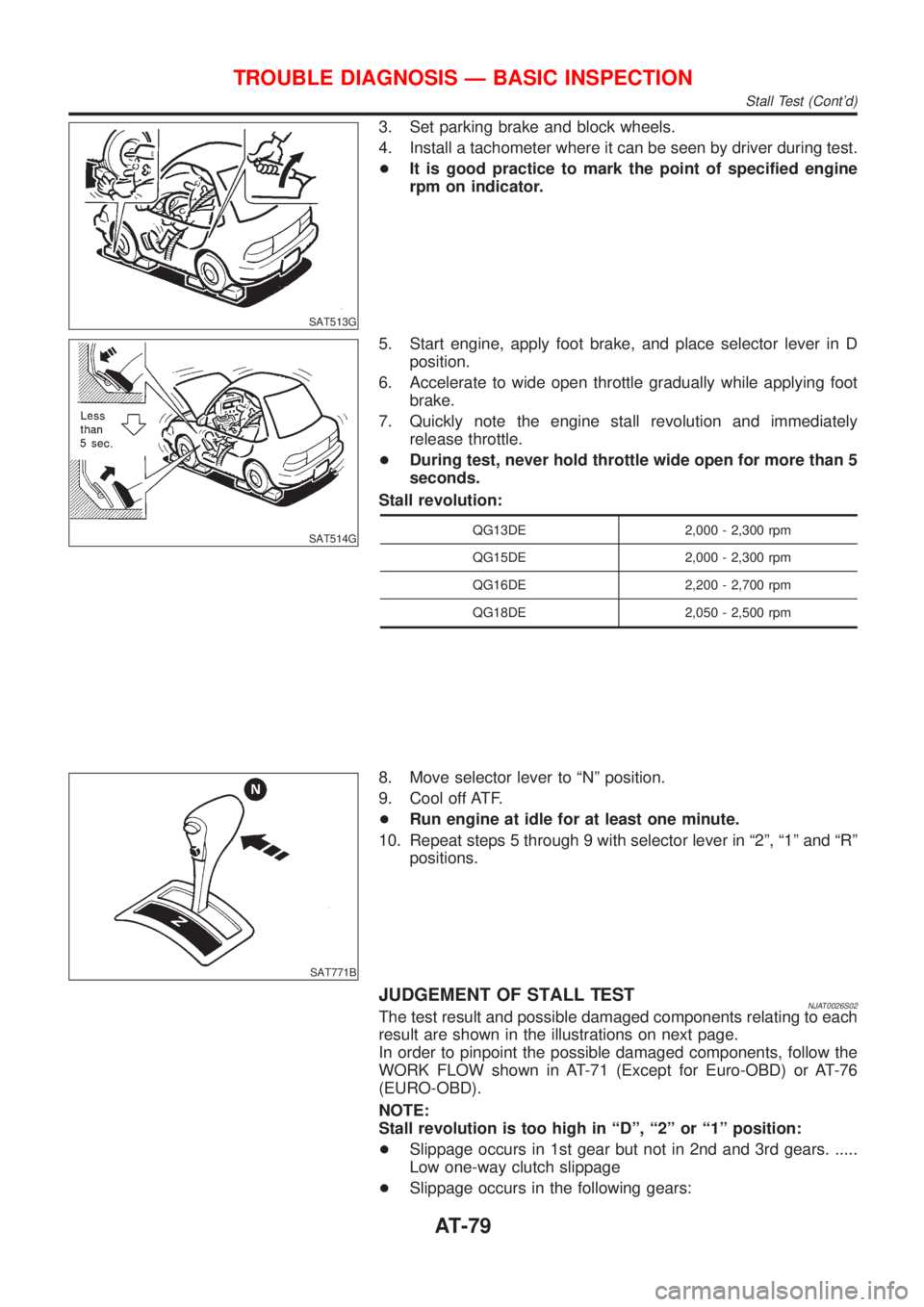
Checking A/T FluidNJAT02281. Warm up engine.
2. Check for fluid leakage.
3. Before driving, fluid level can be checked at fluid temperatures
of 30 to 50ÉC (86 to 122ÉF) using ªCOLDº range on dipstick.
a. Park vehicle on level surface and set parking brake.
b. Start engine and move selector lever through each gear posi-
tion. Leave selector lever in ªPº position.
c. Check fluid level with engine idling.
d. Remove dipstick and note reading. If level is at low side of
either range, and fluid to the charging pipe.
e. Re-insert dipstick into charging pipe as far as it will go.
f. Remove dipstick and note reading. If reading is at low side of
range, add fluid to the charging pipe.
Do not overfill.
4. Drive vehicle for approximately 5 minutes in urban areas.
5. Re-check fluid level at fluid temperatures of 50 to 80ÉC (122
to 176ÉF) using ªHOTº range on dipstick.
SMA853B
6. Check fluid condition.
+If fluid is very dark or smells burned, refer to AT section for
checking operation of A/T. Flush cooling system after repair of
A/T.
+If A/T fluid contains frictional material (clutches, bands, etc.),
replace radiator and flush cooler line using cleaning solvent
and compressed air after repair of A/T. Refer to LC-16, ªRadia-
torº.
SMA027D
Changing A/T FluidNJAT02291. Warm up A/T fluid.
2. Stop engine.
3. Drain A/T fluid from drain plug and refill with new A/T fluid.
Always refill same volume with drained fluid.
Fluid grade:
Nissan Matic ªDº or Genuine Nissan Automatic
Transmission Fluid. Refer to ªRECOMMENDED FLU-
IDS AND LUBRICANTSº, MA-20.
Fluid capacity (With torque converter):
7.0!(6-1/8 Imp qt)
Drain plug:
: 29 - 39 N´m (3.0 - 4.0 kg-m, 22 - 29 ft-lb)
4. Run engine at idle speed for five minutes.
5. Check fluid level and condition. Refer to ªChecking A/T Fluidº.
If fluid is still dirty, repeat steps 2 through 5.
A/T FLUID
Checking A/T Fluid
AT-15
Page 1206 of 2493

Shift MechanismNJAT0013CONSTRUCTIONNJAT0013S01
SAT998I
1. Torque converter
2. Oil pump
3. Input shaft
4. Brake band
5. Reverse clutch
6. High clutch
7. Front sun gear
8. Front pinion gear9. Front internal gear
10. Front planetary carrier
11. Rear sun gear
12. Rear pinion gear
13. Rear internal gear
14. Rear planetary carrier
15. Forward clutch
16. Forward one-way clutch17. Overrun clutch
18. Low one-way clutch
19. Low & reverse brake
20. Parking pawl
21. Parking gear
22. Output shaft
23. Idle gear
24. Output gear
FUNCTION OF CLUTCH AND BRAKENJAT0013S03
Clutch and brake components Abbr. Function
5Reverse clutch R/C To transmit input power to front sun gear7.
6High clutch H/C To transmit input power to front planetary carrier10.
15Forward clutch F/C To connect front planetary carrier10with forward one-way clutch16.
17Overrun clutch O/C To connect front planetary carrier10with rear internal gear13.
4Brake band B/B To lock front sun gear7.
16Forward one-way clutch F/O.C When forward clutch15is engaged, to stop rear internal gear13from rotat-
ing in opposite direction against engine revolution.
18Low one-way clutch L/O.C To stop front planetary carrier10from rotating in opposite direction against
engine revolution.
19Low & reverse brake L & R/B To lock front planetary carrier10.
OVERALL SYSTEM
Shift Mechanism
AT-20
Page 1265 of 2493

SAT513G
3. Set parking brake and block wheels.
4. Install a tachometer where it can be seen by driver during test.
+It is good practice to mark the point of specified engine
rpm on indicator.
SAT514G
5. Start engine, apply foot brake, and place selector lever in D
position.
6. Accelerate to wide open throttle gradually while applying foot
brake.
7. Quickly note the engine stall revolution and immediately
release throttle.
+During test, never hold throttle wide open for more than 5
seconds.
Stall revolution:
QG13DE 2,000 - 2,300 rpm
QG15DE 2,000 - 2,300 rpm
QG16DE 2,200 - 2,700 rpm
QG18DE 2,050 - 2,500 rpm
SAT771B
8. Move selector lever to ªNº position.
9. Cool off ATF.
+Run engine at idle for at least one minute.
10. Repeat steps 5 through 9 with selector lever in ª2º, ª1º and ªRº
positions.
JUDGEMENT OF STALL TESTNJAT0026S02The test result and possible damaged components relating to each
result are shown in the illustrations on next page.
In order to pinpoint the possible damaged components, follow the
WORK FLOW shown in AT-71 (Except for Euro-OBD) or AT-76
(EURO-OBD).
NOTE:
Stall revolution is too high in ªDº, ª2º or ª1º position:
+Slippage occurs in 1st gear but not in 2nd and 3rd gears. .....
Low one-way clutch slippage
+Slippage occurs in the following gears:
TROUBLE DIAGNOSIS Ð BASIC INSPECTION
Stall Test (Cont'd)
AT-79