2001 NISSAN ALMERA N16 cruise control
[x] Cancel search: cruise controlPage 1225 of 2493
![NISSAN ALMERA N16 2001 Electronic Repair Manual Item DisplayMonitor item
Description Remarks
ECU input
signalsMain sig-
nals
Vehicle speed sensor 2
(Meter)VHCL/S SE´MTR
[km/h] or [mph]
XÐ+Vehicle speed com-
puted from signal of
vehicle speed sens NISSAN ALMERA N16 2001 Electronic Repair Manual Item DisplayMonitor item
Description Remarks
ECU input
signalsMain sig-
nals
Vehicle speed sensor 2
(Meter)VHCL/S SE´MTR
[km/h] or [mph]
XÐ+Vehicle speed com-
puted from signal of
vehicle speed sens](/manual-img/5/57351/w960_57351-1224.png)
Item DisplayMonitor item
Description Remarks
ECU input
signalsMain sig-
nals
Vehicle speed sensor 2
(Meter)VHCL/S SE´MTR
[km/h] or [mph]
XÐ+Vehicle speed com-
puted from signal of
vehicle speed sensor is
displayed.Vehicle speed display may
not be accurate under
approx. 10 km/h (6 mph).
It may not indicate 0 km/h
(0 mph) when vehicle is
stationary.
Throttle position sensor THRTL POS SEN
[V] X Ð+Throttle position sensor
signal voltage is dis-
played.
A/T fluid temperature sen-
sorFLUID TEMP SE
[V]
XÐ+A/T fluid temperature
sensor signal voltage is
displayed.
+Signal voltage lowers as
fluid temperature rises.
Battery voltage BATTERY VOLT
[V]XÐ+Source voltage of TCM
is displayed.
Engine speed ENGINE SPEED
[rpm]
XX+Engine speed, com-
puted from engine
speed signal, is dis-
played.Engine speed display may
not be accurate under
approx. 800 rpm. It may
not indicate 0 rpm even
when engine is not run-
ning.
Overdrive control switch OVERDRIVE SW
[ON/OFF]
XÐ+ON/OFF state com-
puted from signal of
overdrive control SW is
displayed.
P/N position switch PN POSI SW
[ON/OFF]
XÐ+ON/OFF state com-
puted from signal of P/N
position SW is dis-
played.
R position switch R POSITION SW
[ON/OFF]
XÐ+ON/OFF state com-
puted from signal of R
position SW is dis-
played.
D position switch D POSITION SW
[ON/OFF]
XÐ+ON/OFF state com-
puted from signal of D
position SW is dis-
played.
2 position switch 2 POSITION SW
[ON/OFF]
XÐ+ON/OFF status, com-
puted from signal of 2
position SW, is dis-
played.
1 position switch 1 POSITION SW
[ON/OFF]
XÐ+ON/OFF status, com-
puted from signal of 1
position SW, is dis-
played.
ASCD cruise signal ASCD-CRUISE
[ON/OFF]
XÐ+Status of ASCD cruise
signal is displayed.
ON ... Cruising state
OFF ... Normal running
state+This is displayed even
when no ASCD is
mounted.
ON BOARD DIAGNOSTIC SYSTEM
DESCRIPTION
EXCEPT FOR EURO-OBD
CONSULT-II (Cont'd)
AT-39
Page 1242 of 2493
![NISSAN ALMERA N16 2001 Electronic Repair Manual Item DisplayMonitor item
Description Remarks
ECU input
signalsMain sig-
nals
R position switch R POSITION SW
[ON/OFF] X Ð+ON/OFF state computed
from signal of R position
SW is displayed.
D position s NISSAN ALMERA N16 2001 Electronic Repair Manual Item DisplayMonitor item
Description Remarks
ECU input
signalsMain sig-
nals
R position switch R POSITION SW
[ON/OFF] X Ð+ON/OFF state computed
from signal of R position
SW is displayed.
D position s](/manual-img/5/57351/w960_57351-1241.png)
Item DisplayMonitor item
Description Remarks
ECU input
signalsMain sig-
nals
R position switch R POSITION SW
[ON/OFF] X Ð+ON/OFF state computed
from signal of R position
SW is displayed.
D position switch D POSITION SW
[ON/OFF] X Ð+ON/OFF state computed
from signal of D position
SW is displayed.
2 position switch 2 POSITION SW
[ON/OFF]
XÐ+ON/OFF status, com-
puted from signal of 2
position SW, is dis-
played.
1 position switch 1 POSITION SW
[ON/OFF]
XÐ+ON/OFF status, com-
puted from signal of 1
position SW, is dis-
played.
ASCD cruise signal ASCD-CRUISE
[ON/OFF]
XÐ+Status of ASCD cruise
signal is displayed.
ON ... Cruising state
OFF ... Normal running
state+This is displayed even
when no ASCD is
mounted.
ASCD OD cut signal ASCD-OD CUT
[ON/OFF]
XÐ+Status of ASCD OD
release signal is dis-
played.
ON ... OD released
OFF ... OD not released+This is displayed even
when no ASCD is
mounted.
Kickdown switch KICKDOWN SW
[ON/OFF]
XÐ+ON/OFF status, com-
puted from signal of
kickdown SW, is dis-
played.+This is displayed even
when no kickdown
switch is equipped.
Closed throttle position
switchCLOSED
THL/SW
[ON/OFF]XÐ+ON/OFF status, com-
puted from signal of
closed throttle position
SW, is displayed.
Wide open throttle position
switchW/O THRL/P-SW
[ON/OFF]
XÐ+ON/OFF status, com-
puted from signal of
wide open throttle posi-
tion SW, is displayed.
Gear position GEAR
ÐX+Gear position data used
for computation by
TCM, is displayed.
Selector lever position SLCT LVR POSI
ÐX+Selector lever position
data, used for computa-
tion by TCM, is dis-
played.+A specific value used for
control is displayed if
fail-safe is activated due
to error.
Vehicle speed VEHICLE
SPEED
[km/h] or [mph]ÐX+Vehicle speed data,
used for computation by
TCM, is displayed.
Stop lamp switch BRAKE SW
[ON/OFF]
XÐ+ON/OFF status are dis-
played.
ON: Brake pedal is
depressed.
OFF: Brake pedal is
released.
ON BOARD DIAGNOSTIC SYSTEM DESCRIPTIONEURO-OBD
CONSULT-II (Cont'd)
AT-56
Page 1256 of 2493
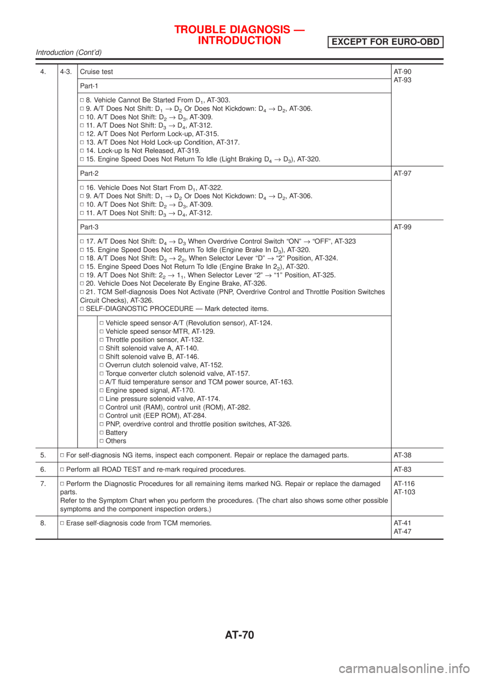
4. 4-3. Cruise testAT-90
AT-93
Part-1
N8. Vehicle Cannot Be Started From D
1, AT-303.
N9. A/T Does Not Shift: D
1®D2Or Does Not Kickdown: D4®D2, AT-306.
N10. A/T Does Not Shift: D
2®D3, AT-309.
N11. A/T Does Not Shift: D
3®D4, AT-312.
N12. A/T Does Not Perform Lock-up, AT-315.
N13. A/T Does Not Hold Lock-up Condition, AT-317.
N14. Lock-up Is Not Released, AT-319.
N15. Engine Speed Does Not Return To Idle (Light Braking D
4®D3), AT-320.
Part-2AT-97
N16. Vehicle Does Not Start From D
1, AT-322.
N9. A/T Does Not Shift: D
1®D2Or Does Not Kickdown: D4®D2, AT-306.
N10. A/T Does Not Shift: D
2®D3, AT-309.
N11. A/T Does Not Shift: D
3®D4, AT-312.
Part-3AT-99
N17. A/T Does Not Shift: D
4®D3When Overdrive Control Switch ªONº®ªOFFº, AT-323
N15. Engine Speed Does Not Return To Idle (Engine Brake In D
3), AT-320.
N18. A/T Does Not Shift: D
3®22, When Selector Lever ªDº®ª2º Position, AT-324.
N15. Engine Speed Does Not Return To Idle (Engine Brake In 2
2), AT-320.
N19. A/T Does Not Shift: 2
2®11, When Selector Lever ª2º®ª1º Position, AT-325.
N20. Vehicle Does Not Decelerate By Engine Brake, AT-326.
N21. TCM Self-diagnosis Does Not Activate (PNP, Overdrive Control and Throttle Position Switches
Circuit Checks), AT-326.
NSELF-DIAGNOSTIC PROCEDURE Ð Mark detected items.
NVehicle speed sensor´A/T (Revolution sensor), AT-124.
NVehicle speed sensor´MTR, AT-129.
NThrottle position sensor, AT-132.
NShift solenoid valve A, AT-140.
NShift solenoid valve B, AT-146.
NOverrun clutch solenoid valve, AT-152.
NTorque converter clutch solenoid valve, AT-157.
NA/T fluid temperature sensor and TCM power source, AT-163.
NEngine speed signal, AT-170.
NLine pressure solenoid valve, AT-174.
NControl unit (RAM), control unit (ROM), AT-282.
NControl unit (EEP ROM), AT-284.
NPNP, overdrive control and throttle position switches, AT-326.
NBattery
NOthers
5.NFor self-diagnosis NG items, inspect each component. Repair or replace the damaged parts. AT-38
6.NPerform all ROAD TEST and re-mark required procedures. AT-83
7.NPerform the Diagnostic Procedures for all remaining items marked NG. Repair or replace the damaged
parts.
Refer to the Symptom Chart when you perform the procedures. (The chart also shows some other possible
symptoms and the component inspection orders.)AT-116
AT-103
8.NErase self-diagnosis code from TCM memories. AT-41
AT-47
TROUBLE DIAGNOSIS Ð
INTRODUCTION
EXCEPT FOR EURO-OBD
Introduction (Cont'd)
AT-70
Page 1261 of 2493
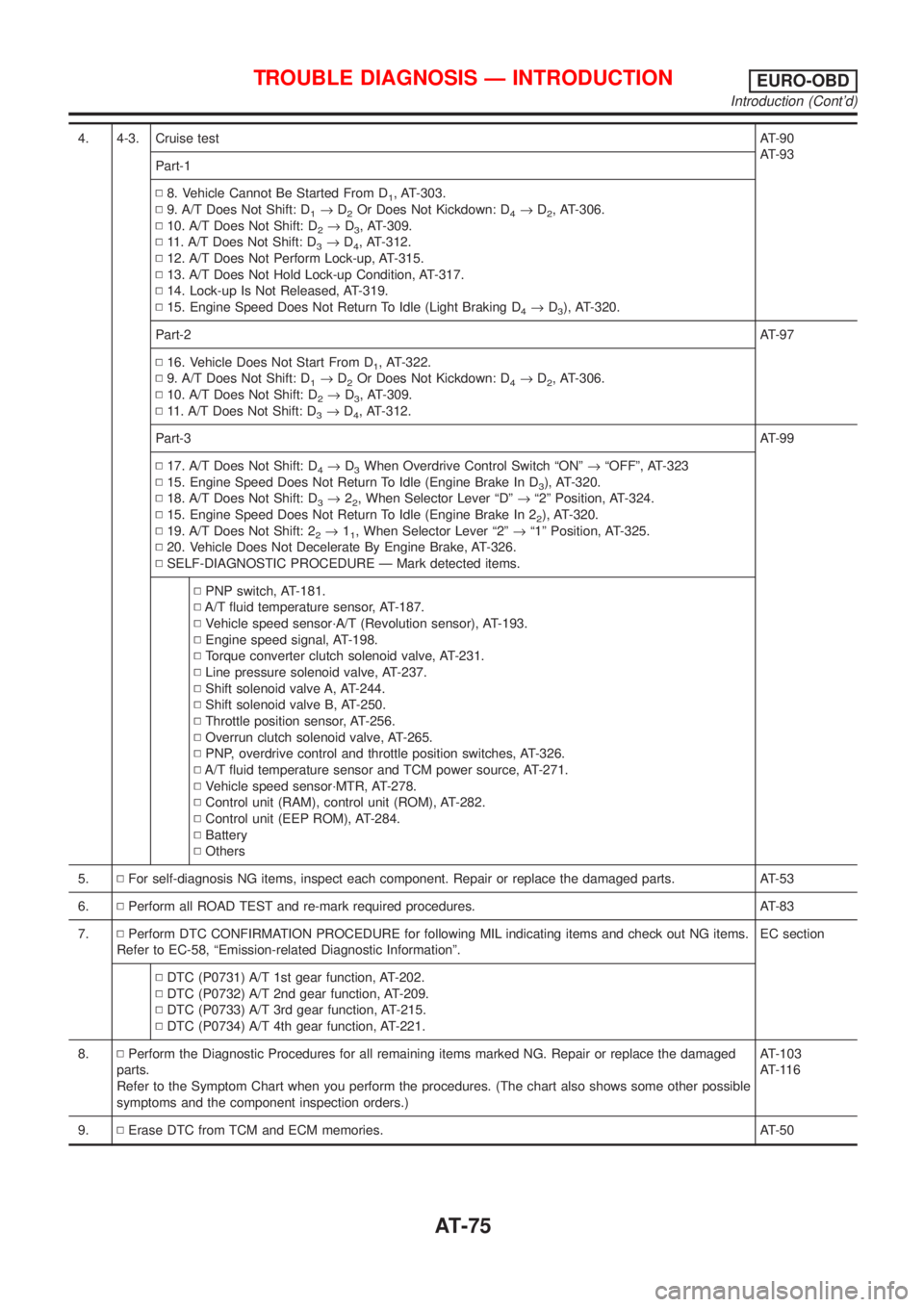
4. 4-3. Cruise testAT-90
AT-93
Part-1
N8. Vehicle Cannot Be Started From D
1, AT-303.
N9. A/T Does Not Shift: D
1®D2Or Does Not Kickdown: D4®D2, AT-306.
N10. A/T Does Not Shift: D
2®D3, AT-309.
N11. A/T Does Not Shift: D
3®D4, AT-312.
N12. A/T Does Not Perform Lock-up, AT-315.
N13. A/T Does Not Hold Lock-up Condition, AT-317.
N14. Lock-up Is Not Released, AT-319.
N15. Engine Speed Does Not Return To Idle (Light Braking D
4®D3), AT-320.
Part-2AT-97
N16. Vehicle Does Not Start From D
1, AT-322.
N9. A/T Does Not Shift: D
1®D2Or Does Not Kickdown: D4®D2, AT-306.
N10. A/T Does Not Shift: D
2®D3, AT-309.
N11. A/T Does Not Shift: D
3®D4, AT-312.
Part-3AT-99
N17. A/T Does Not Shift: D
4®D3When Overdrive Control Switch ªONº®ªOFFº, AT-323
N15. Engine Speed Does Not Return To Idle (Engine Brake In D
3), AT-320.
N18. A/T Does Not Shift: D
3®22, When Selector Lever ªDº®ª2º Position, AT-324.
N15. Engine Speed Does Not Return To Idle (Engine Brake In 2
2), AT-320.
N19. A/T Does Not Shift: 2
2®11, When Selector Lever ª2º®ª1º Position, AT-325.
N20. Vehicle Does Not Decelerate By Engine Brake, AT-326.
NSELF-DIAGNOSTIC PROCEDURE Ð Mark detected items.
NPNP switch, AT-181.
NA/T fluid temperature sensor, AT-187.
NVehicle speed sensor´A/T (Revolution sensor), AT-193.
NEngine speed signal, AT-198.
NTorque converter clutch solenoid valve, AT-231.
NLine pressure solenoid valve, AT-237.
NShift solenoid valve A, AT-244.
NShift solenoid valve B, AT-250.
NThrottle position sensor, AT-256.
NOverrun clutch solenoid valve, AT-265.
NPNP, overdrive control and throttle position switches, AT-326.
NA/T fluid temperature sensor and TCM power source, AT-271.
NVehicle speed sensor´MTR, AT-278.
NControl unit (RAM), control unit (ROM), AT-282.
NControl unit (EEP ROM), AT-284.
NBattery
NOthers
5.NFor self-diagnosis NG items, inspect each component. Repair or replace the damaged parts. AT-53
6.NPerform all ROAD TEST and re-mark required procedures. AT-83
7.NPerform DTC CONFIRMATION PROCEDURE for following MIL indicating items and check out NG items.
Refer to EC-58, ªEmission-related Diagnostic Informationº.EC section
NDTC (P0731) A/T 1st gear function, AT-202.
NDTC (P0732) A/T 2nd gear function, AT-209.
NDTC (P0733) A/T 3rd gear function, AT-215.
NDTC (P0734) A/T 4th gear function, AT-221.
8.NPerform the Diagnostic Procedures for all remaining items marked NG. Repair or replace the damaged
parts.
Refer to the Symptom Chart when you perform the procedures. (The chart also shows some other possible
symptoms and the component inspection orders.)AT-103
AT-116
9.NErase DTC from TCM and ECM memories. AT-50
TROUBLE DIAGNOSIS Ð INTRODUCTIONEURO-OBD
Introduction (Cont'd)
AT-75
Page 1269 of 2493
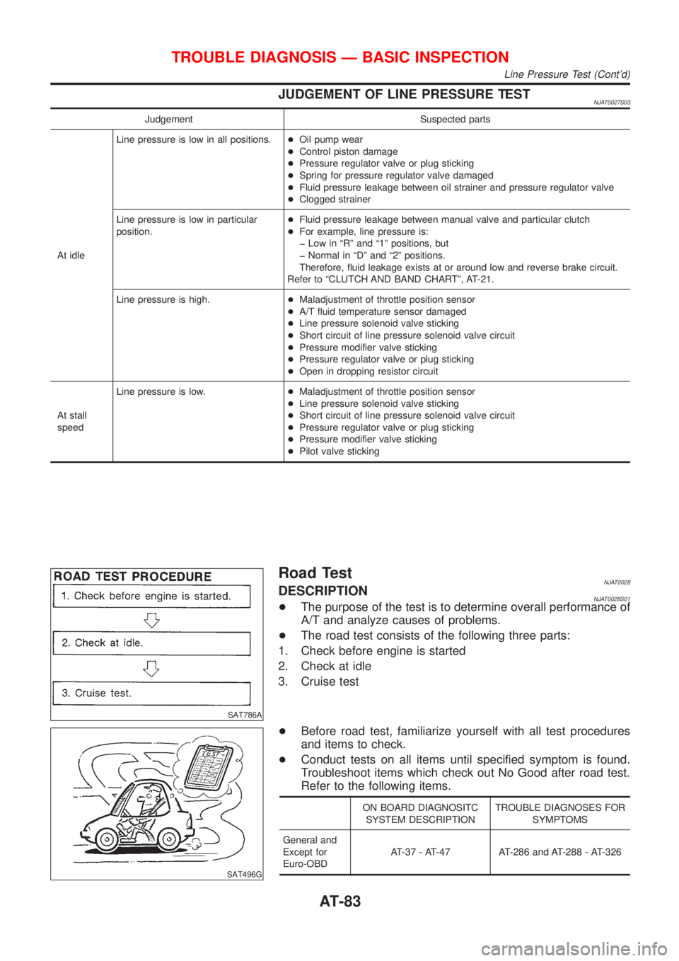
JUDGEMENT OF LINE PRESSURE TESTNJAT0027S03
Judgement Suspected parts
At idleLine pressure is low in all positions.+Oil pump wear
+Control piston damage
+Pressure regulator valve or plug sticking
+Spring for pressure regulator valve damaged
+Fluid pressure leakage between oil strainer and pressure regulator valve
+Clogged strainer
Line pressure is low in particular
position.+Fluid pressure leakage between manual valve and particular clutch
+For example, line pressure is:
þ Low in ªRº and ª1º positions, but
þ Normal in ªDº and ª2º positions.
Therefore, fluid leakage exists at or around low and reverse brake circuit.
Refer to ªCLUTCH AND BAND CHARTº, AT-21.
Line pressure is high.+Maladjustment of throttle position sensor
+A/T fluid temperature sensor damaged
+Line pressure solenoid valve sticking
+Short circuit of line pressure solenoid valve circuit
+Pressure modifier valve sticking
+Pressure regulator valve or plug sticking
+Open in dropping resistor circuit
At stall
speedLine pressure is low.+Maladjustment of throttle position sensor
+Line pressure solenoid valve sticking
+Short circuit of line pressure solenoid valve circuit
+Pressure regulator valve or plug sticking
+Pressure modifier valve sticking
+Pilot valve sticking
SAT786A
Road TestNJAT0028DESCRIPTIONNJAT0028S01+The purpose of the test is to determine overall performance of
A/T and analyze causes of problems.
+The road test consists of the following three parts:
1. Check before engine is started
2. Check at idle
3. Cruise test
SAT496G
+Before road test, familiarize yourself with all test procedures
and items to check.
+Conduct tests on all items until specified symptom is found.
Troubleshoot items which check out No Good after road test.
Refer to the following items.
ON BOARD DIAGNOSITC
SYSTEM DESCRIPTIONTROUBLE DIAGNOSES FOR
SYMPTOMS
General and
Except for
Euro-OBDAT-37 - AT-47 AT-286 and AT-288 - AT-326
TROUBLE DIAGNOSIS Ð BASIC INSPECTION
Line Pressure Test (Cont'd)
AT-83
Page 1279 of 2493
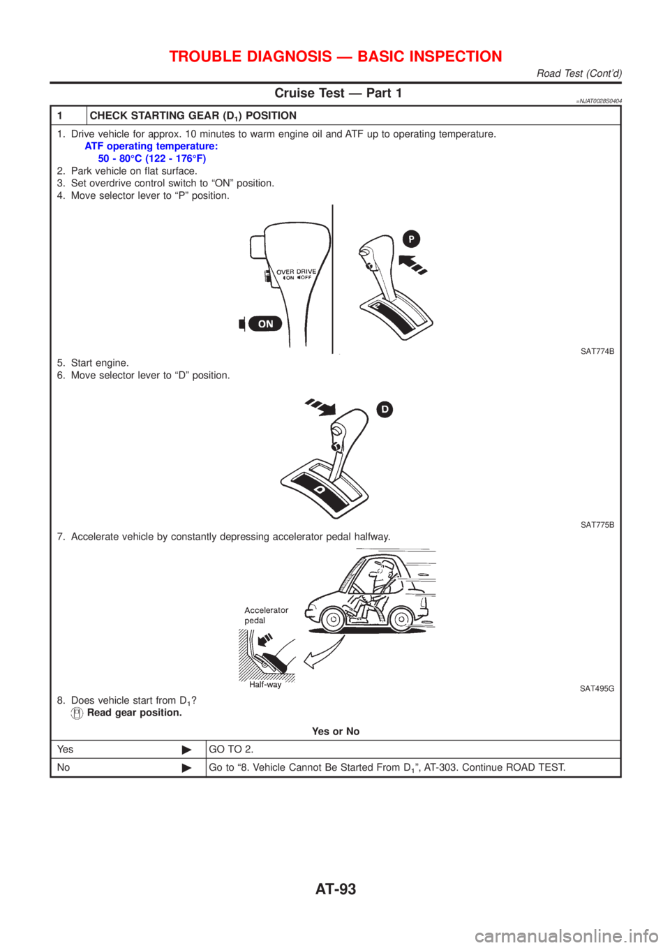
Cruise Test Ð Part 1=NJAT0028S0404
1 CHECK STARTING GEAR (D1) POSITION
1. Drive vehicle for approx. 10 minutes to warm engine oil and ATF up to operating temperature.
ATF operating temperature:
50 - 80ÉC (122 - 176ÉF)
2. Park vehicle on flat surface.
3. Set overdrive control switch to ªONº position.
4. Move selector lever to ªPº position.
SAT774B
5. Start engine.
6. Move selector lever to ªDº position.
SAT775B
7. Accelerate vehicle by constantly depressing accelerator pedal halfway.
SAT495G
8. Does vehicle start from D1?
Read gear position.
YesorNo
Ye s©GO TO 2.
No©Go to ª8. Vehicle Cannot Be Started From D
1º, AT-303. Continue ROAD TEST.
TROUBLE DIAGNOSIS Ð BASIC INSPECTION
Road Test (Cont'd)
AT-93
Page 1283 of 2493
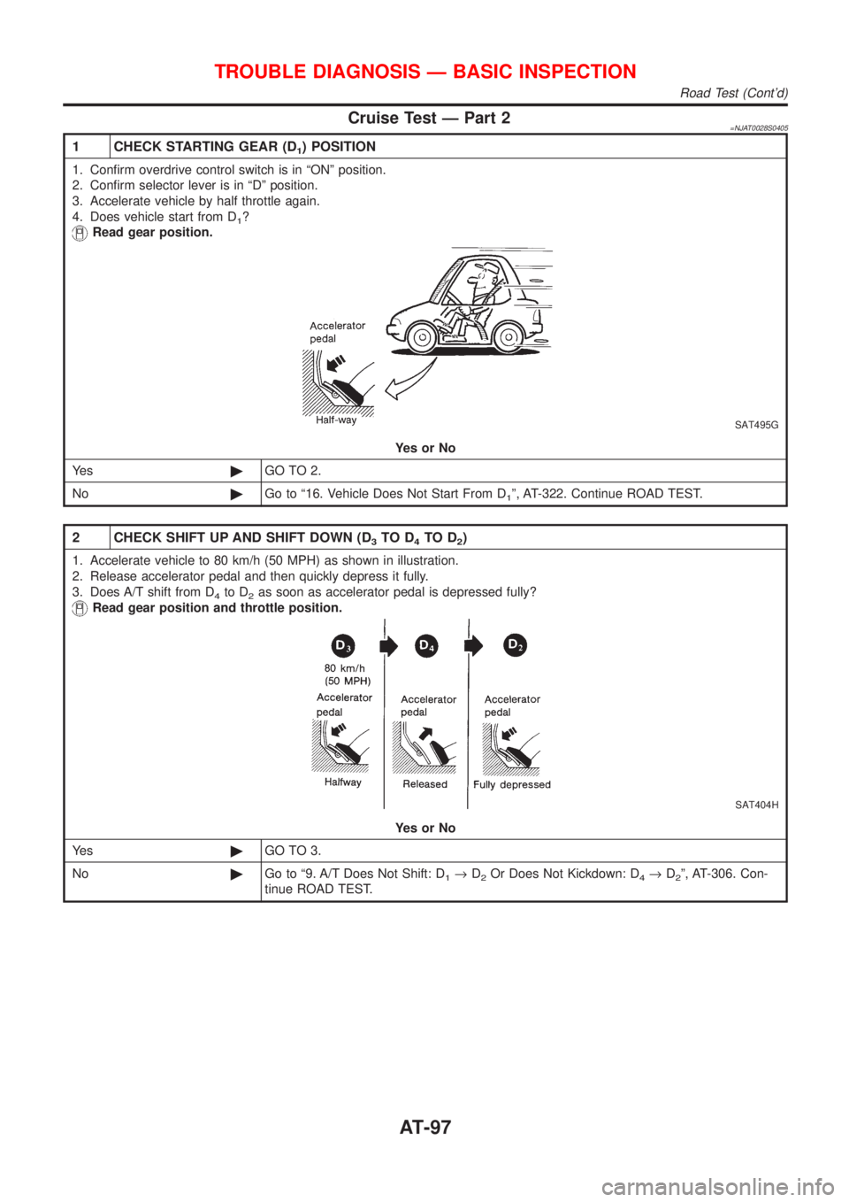
Cruise Test Ð Part 2=NJAT0028S0405
1 CHECK STARTING GEAR (D1) POSITION
1. Confirm overdrive control switch is in ªONº position.
2. Confirm selector lever is in ªDº position.
3. Accelerate vehicle by half throttle again.
4. Does vehicle start from D
1?
Read gear position.
SAT495G
YesorNo
Ye s©GO TO 2.
No©Go to ª16. Vehicle Does Not Start From D
1º, AT-322. Continue ROAD TEST.
2 CHECK SHIFT UP AND SHIFT DOWN (D3TO D4TO D2)
1. Accelerate vehicle to 80 km/h (50 MPH) as shown in illustration.
2. Release accelerator pedal and then quickly depress it fully.
3. Does A/T shift from D
4to D2as soon as accelerator pedal is depressed fully?
Read gear position and throttle position.
SAT404H
YesorNo
Ye s©GO TO 3.
No©Go to ª9. A/T Does Not Shift: D
1®D2Or Does Not Kickdown: D4®D2º, AT-306. Con-
tinue ROAD TEST.
TROUBLE DIAGNOSIS Ð BASIC INSPECTION
Road Test (Cont'd)
AT-97
Page 1285 of 2493
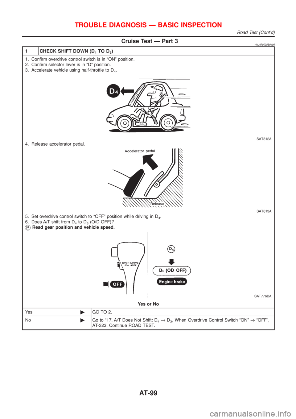
Cruise Test Ð Part 3=NJAT0028S0406
1 CHECK SHIFT DOWN (D4TO D3)
1. Confirm overdrive control switch is in ªONº position.
2. Confirm selector lever is in ªDº position.
3. Accelerate vehicle using half-throttle to D
4.
SAT812A
4. Release accelerator pedal.
SAT813A
5. Set overdrive control switch to ªOFFº position while driving in D4.
6. Does A/T shift from D
4to D3(O/D OFF)?
Read gear position and vehicle speed.
SAT776BA
YesorNo
Ye s©GO TO 2.
No©Go to ª17. A/T Does Not Shift: D
4®D3, When Overdrive Control Switch ªONº®ªOFFº,
AT-323. Continue ROAD TEST.
TROUBLE DIAGNOSIS Ð BASIC INSPECTION
Road Test (Cont'd)
AT-99