2001 NISSAN ALMERA N16 electrical
[x] Cancel search: electricalPage 1897 of 2493
Service NoticeNJBT0001+When removing or installing various parts, place a cloth or padding onto the vehicle body to prevent
scratches.
+Handle trim, molding, instruments, grille, etc. carefully during removing or installing. Be careful not to oil
or damage them.
+Apply sealing compound where necessary when installing parts.
+When applying sealing compound, be careful that the sealing compound does not protrude from parts.
+When replacing any metal parts (for example body outer panel, members, etc.), be sure to take rust pre-
vention measures.
Supplemental Restraint System (SRS) ªAIR
BAGº and ªSEAT BELT PRE-TENSIONERº
NJBT0002The Supplemental Restraint System such as ªAIR BAGº and ªSEAT BELT PRE-TENSIONERº used along with
a seat belt, helps to reduce the risk or severity of injury to the driver and front passenger for certain types of
collision. The SRS system composition which is available to NISSAN MODEL N16 is as follows (The compo-
sition varies according to the destination and optional equipment.):
+For a frontal collision
The Supplemental Restraint System consists of driver air bag module (located in the center of the steer-
ing wheel), front passenger air bag module (located on the instrument panel on passenger side), front seat
belt pre-tensioners, a diagnosis sensor unit, warning lamp, wiring harness and spiral cable.
+For a side collision
The Supplemental Restraint System consists of front side air bag module (located in the outer side of front
seat), side air bag (satellite) sensor, diagnosis sensor unit (one of components of air bags for a frontal
collision), wiring harness, warning lamp (one of components of air bags for a frontal collision).
Information necessary to service the system safely is included in theRS sectionof this Service Manual.
WARNING:
+To avoid rendering the SRS inoperative, which could increase the risk of personal injury or death
in the event of a collision which would result in air bag inflation, all maintenance should be per-
formed by an authorized NISSAN dealer.
+Improper maintenance, including incorrect removal and installation of the SRS, can lead to per-
sonal injury caused by unintentional activation of the system. For removal of Spiral Cable and Air
Bag Module, see the RS section.
+Do not use electrical test equipment on any circuit related to the SRS unless instructed to in this
Service Manual. SRS wiring harnesses can be identified by yellow harness connector.
PRECAUTIONS
Service Notice
BT-3
Page 1974 of 2493
Supplemental Restraint System (SRS) ªAIR
BAGº and ªSEAT BELT PRE-TENSIONERº
NJHA0190The Supplemental Restraint System such as ªAIR BAGº and ªSEAT BELT PRE-TENSIONERº used along with
a seat belt, helps to reduce the risk or severity of injury to the driver and front passenger for certain types of
collision. The SRS system composition which is available to NISSAN MODEL N16 is as follows (The compo-
sition varies according to the destination and optional equipment.):
+For a frontal collision
The Supplemental Restraint System consists of driver air bag module (located in the center of the steer-
ing wheel), front passenger air bag module (located on the instrument panel on passenger side), front seat
belt pre-tensioners, a diagnosis sensor unit, warning lamp, wiring harness and spiral cable.
+For a side collision
The Supplemental Restraint System consists of front side air bag module (located in the outer side of front
seat), side air bag (satellite) sensor, diagnosis sensor unit (one of components of air bags for a frontal
collision), wiring harness, warning lamp (one of components of air bags for a frontal collision).
Information necessary to service the system safely is included in theRS sectionof this Service Manual.
WARNING:
+To avoid rendering the SRS inoperative, which could increase the risk of personal injury or death
in the event of a collision which would result in air bag inflation, all maintenance should be per-
formed by an authorized NISSAN dealer.
+Improper maintenance, including incorrect removal and installation of the SRS, can lead to per-
sonal injury caused by unintentional activation of the system. For removal of Spiral Cable and Air
Bag Module, see the RS section.
+Do not use electrical test equipment on any circuit related to the SRS unless instructed to in this
Service Manual. Spiral cable and wiring harnesses covered with yellow insulation tape either just
before the harness connectors or for the complete harness are related to the SRS.
Precautions for Working with HFC-134a
(R-134a)
NJHA0113WARNING:
+CFC-12 (R-12) refrigerant and HFC-134a (R-134a) refrigerant are not compatible. These refrigerants
must never be mixed, even in the smallest amounts. If the refrigerants are mixed, compressor fail-
ure is likely to occur.
+Use only specified lubricant for the HFC-134a (R-134a) A/C system and HFC-134a (R-134a) compo-
nents. If lubricant other than that specified is used, compressor failure is likely to occur.
+The specified HFC-134a (R-134a) lubricant rapidly absorbs moisture from the atmosphere. The fol-
lowing handling precautions must be observed:
a) When removing refrigerant components from a vehicle, immediately cap (seal) the component to
minimize the entry of moisture from the atmosphere.
b) When installing refrigerant components to a vehicle, do not remove the caps (unseal) until just
before connecting the components. Connect all refrigerant loop components as quickly as pos-
sible to minimize the entry of moisture into system.
c) Only use the specified lubricant from a sealed container. Immediately reseal containers of lubri-
cant. Without proper sealing, lubricant will become moisture saturated and should not be used.
d) Avoid breathing A/C refrigerant and lubricant vapor or mist. Exposure may irritate eyes, nose
and throat. Remove R-134a from the A/C system, using certified service equipment meeting
requirements of R-134a recycling equipment, or R-134a recovery equipment. If accidental system
discharge occurs, ventilate work area before resuming service. Additional health and safety
information may be obtained from refrigerant and lubricant manufacturers.
e) Do not allow lubricant (Nissan A/C System Oil Type S) to come in contact with styrofoam parts.
Damage may result.
General Refrigerant PrecautionsNJHA0114WARNING:
+Do not release refrigerant into the air. Use approved recovery/recycling equipment to capture the
refrigerant every time an air conditioning system is discharged.
+Always wear eye and hand protection (goggles and gloves) when working with any refrigerant or
air conditioning system.
PRECAUTIONS
Supplemental Restraint System (SRS) ªAIR BAGº and ªSEAT BELT PRE-TENSIONERº
HA-2
Page 1980 of 2493
Wiring Diagrams and Trouble DiagnosisNJHA0118When you read wiring diagrams, refer to the following:
+GI-12, ªHOW TO READ WIRING DIAGRAMSº
+Sedan: EL-23 (QG), EL-0 (YD), Hatchback: EL-12, ªWiring
Diagram РPOWER к.
When you perform trouble diagnosis, refer to the following:
+GI-32, ªHOW TO FOLLOW TROUBLE DIAGNOSESº
+GI-21, ªHOW TO PERFORM EFFICIENT DIAGNOSIS FOR
AN ELECTRICAL INCIDENTº
PRECAUTIONS
Wiring Diagrams and Trouble Diagnosis
HA-8
Page 1983 of 2493
HFC-134a (R-134a) Service Tools and
Equipment
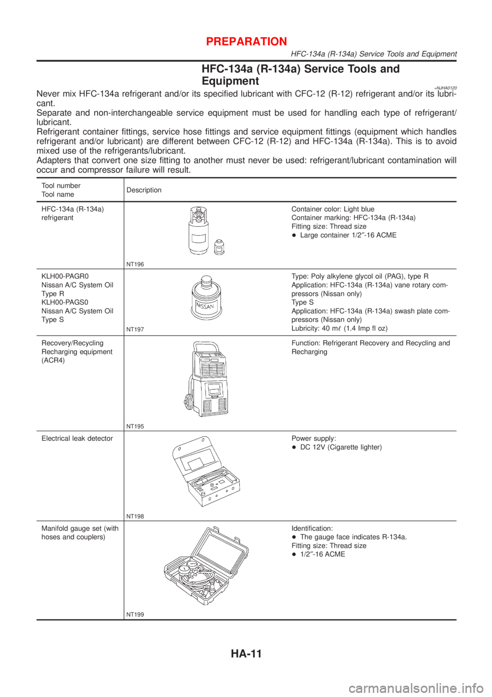
=NJHA0120Never mix HFC-134a refrigerant and/or its specified lubricant with CFC-12 (R-12) refrigerant and/or its lubri-
cant.
Separate and non-interchangeable service equipment must be used for handling each type of refrigerant/
lubricant.
Refrigerant container fittings, service hose fittings and service equipment fittings (equipment which handles
refrigerant and/or lubricant) are different between CFC-12 (R-12) and HFC-134a (R-134a). This is to avoid
mixed use of the refrigerants/lubricant.
Adapters that convert one size fitting to another must never be used: refrigerant/lubricant contamination will
occur and compressor failure will result.
Tool number
Tool nameDescription
HFC-134a (R-134a)
refrigerant
NT196
Container color: Light blue
Container marking: HFC-134a (R-134a)
Fitting size: Thread size
+Large container 1/2²-16 ACME
KLH00-PAGR0
Nissan A/C System Oil
Type R
KLH00-PAGS0
Nissan A/C System Oil
Type S
NT197
Type: Poly alkylene glycol oil (PAG), type R
Application: HFC-134a (R-134a) vane rotary com-
pressors (Nissan only)
Type S
Application: HFC-134a (R-134a) swash plate com-
pressors (Nissan only)
Lubricity: 40 m!(1.4 Imp fl oz)
Recovery/Recycling
Recharging equipment
(ACR4)
NT195
Function: Refrigerant Recovery and Recycling and
Recharging
Electrical leak detector
NT198
Power supply:
+DC 12V (Cigarette lighter)
Manifold gauge set (with
hoses and couplers)
NT199
Identification:
+The gauge face indicates R-134a.
Fitting size: Thread size
+1/2²-16 ACME
PREPARATION
HFC-134a (R-134a) Service Tools and Equipment
HA-11
Page 2017 of 2493
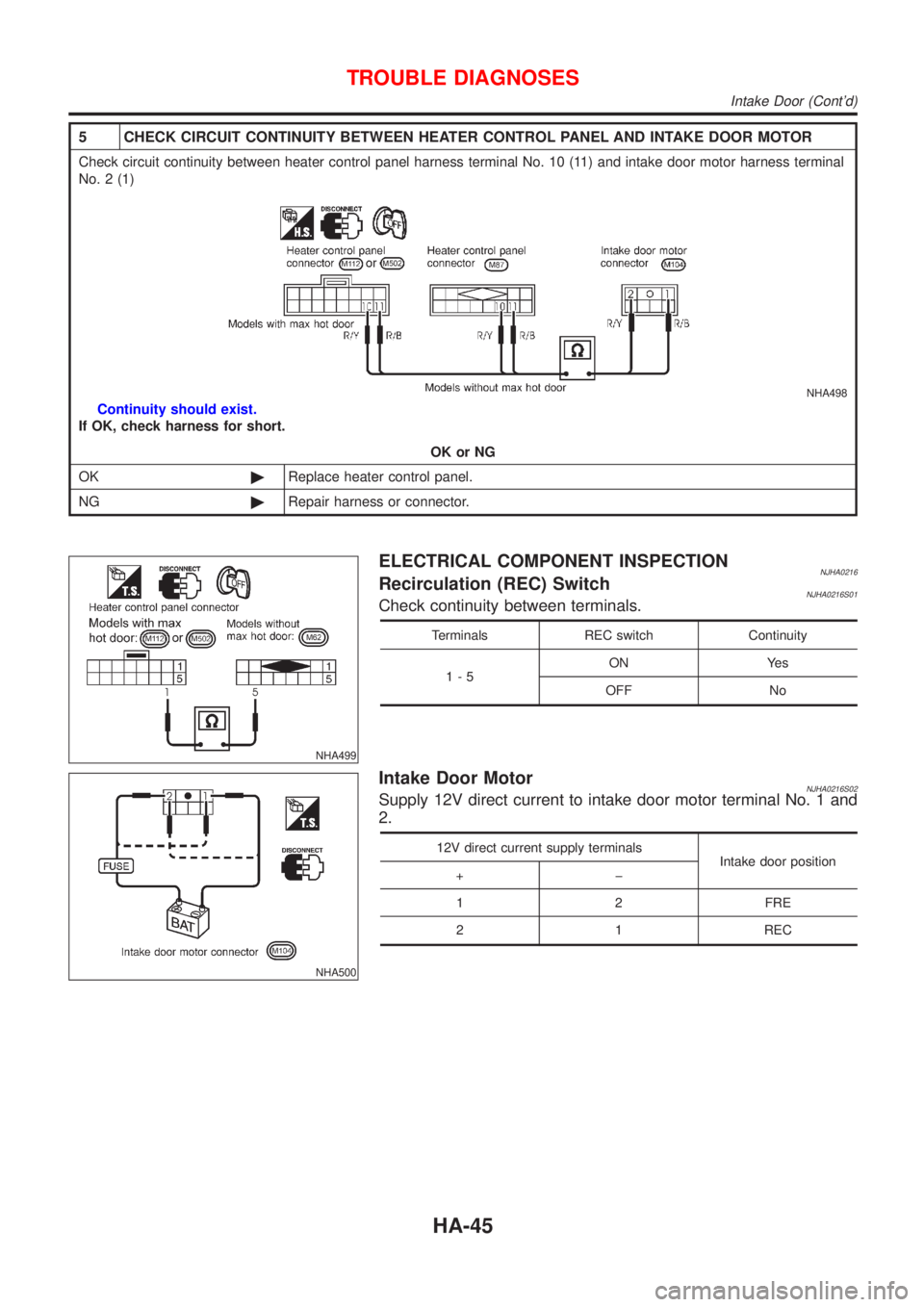
5 CHECK CIRCUIT CONTINUITY BETWEEN HEATER CONTROL PANEL AND INTAKE DOOR MOTOR
Check circuit continuity between heater control panel harness terminal No. 10 (11) and intake door motor harness terminal
No. 2 (1)
NHA498
Continuity should exist.
If OK, check harness for short.
OK or NG
OK©Replace heater control panel.
NG©Repair harness or connector.
NHA499
ELECTRICAL COMPONENT INSPECTIONNJHA0216Recirculation (REC) SwitchNJHA0216S01Check continuity between terminals.
Terminals REC switch Continuity
1-5ON Yes
OFF No
NHA500
Intake Door MotorNJHA0216S02Supply 12V direct current to intake door motor terminal No. 1 and
2.
12V direct current supply terminals
Intake door position
+þ
1 2 FRE
2 1 REC
TROUBLE DIAGNOSES
Intake Door (Cont'd)
HA-45
Page 2028 of 2493
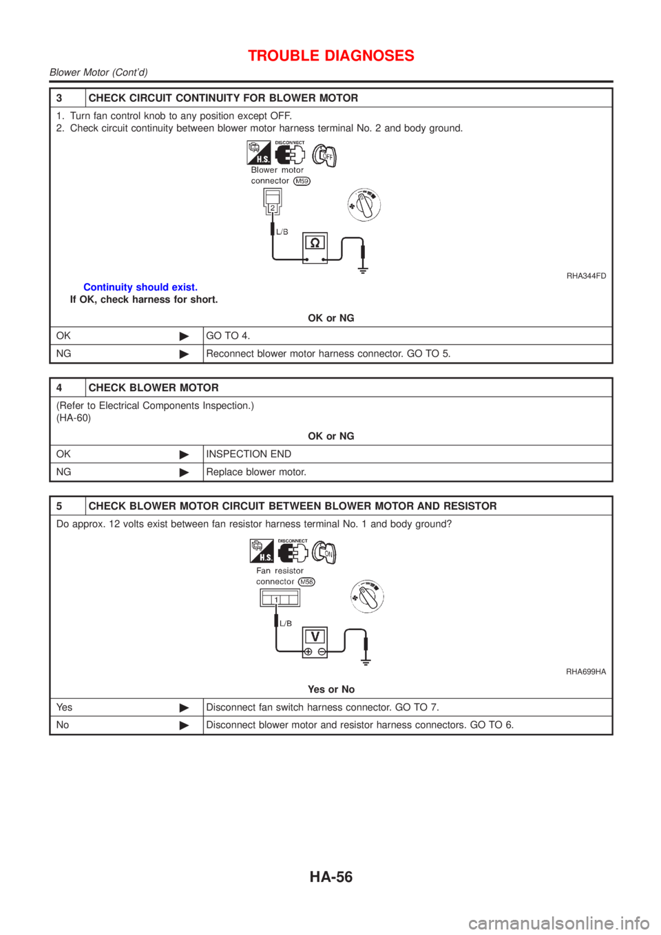
3 CHECK CIRCUIT CONTINUITY FOR BLOWER MOTOR
1. Turn fan control knob to any position except OFF.
2. Check circuit continuity between blower motor harness terminal No. 2 and body ground.
RHA344FD
Continuity should exist.
If OK, check harness for short.
OK or NG
OK©GO TO 4.
NG©Reconnect blower motor harness connector. GO TO 5.
4 CHECK BLOWER MOTOR
(Refer to Electrical Components Inspection.)
(HA-60)
OK or NG
OK©INSPECTION END
NG©Replace blower motor.
5 CHECK BLOWER MOTOR CIRCUIT BETWEEN BLOWER MOTOR AND RESISTOR
Do approx. 12 volts exist between fan resistor harness terminal No. 1 and body ground?
RHA699HA
YesorNo
Ye s©Disconnect fan switch harness connector. GO TO 7.
No©Disconnect blower motor and resistor harness connectors. GO TO 6.
TROUBLE DIAGNOSES
Blower Motor (Cont'd)
HA-56
Page 2029 of 2493
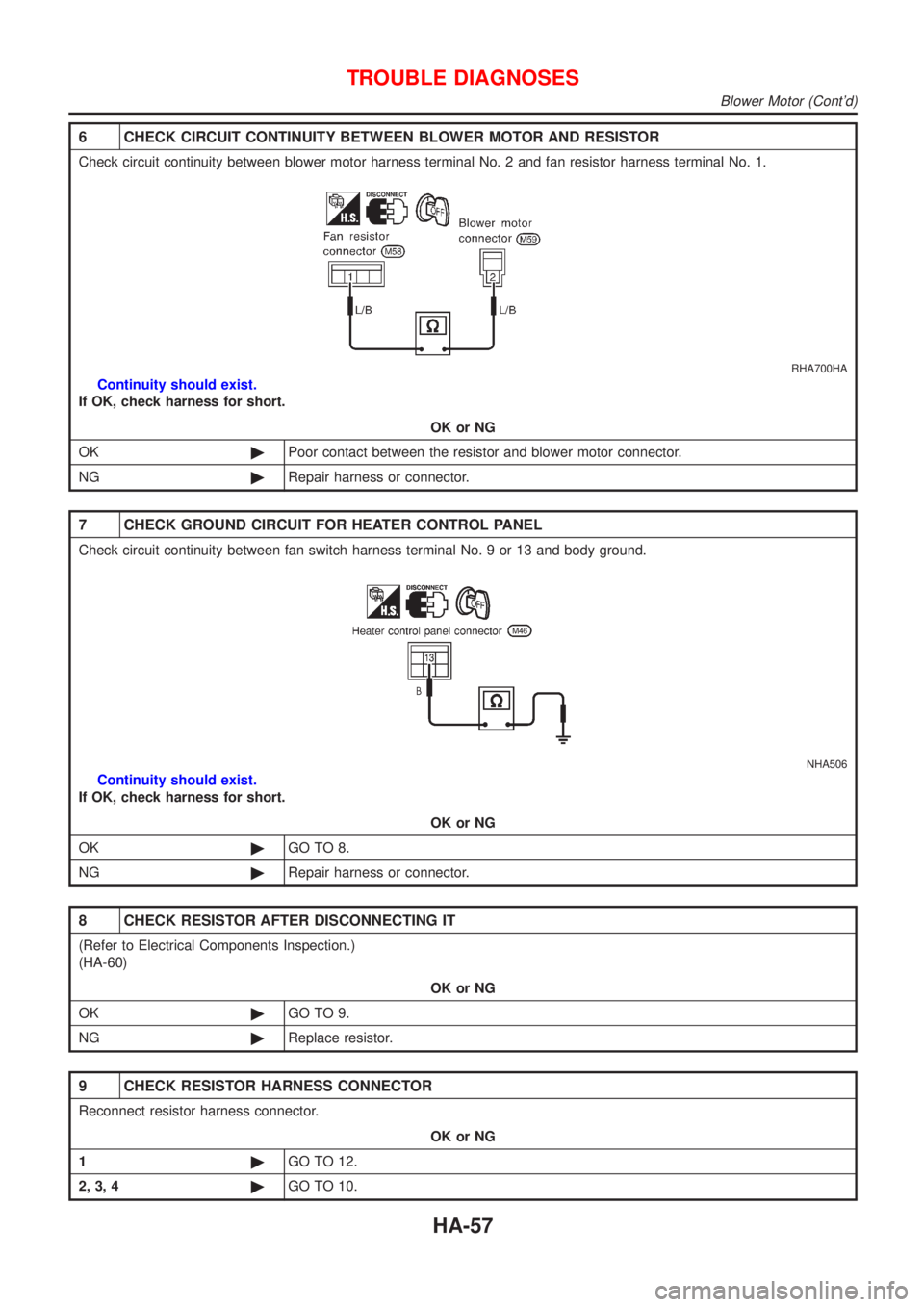
6 CHECK CIRCUIT CONTINUITY BETWEEN BLOWER MOTOR AND RESISTOR
Check circuit continuity between blower motor harness terminal No. 2 and fan resistor harness terminal No. 1.
RHA700HA
Continuity should exist.
If OK, check harness for short.
OK or NG
OK©Poor contact between the resistor and blower motor connector.
NG©Repair harness or connector.
7 CHECK GROUND CIRCUIT FOR HEATER CONTROL PANEL
Check circuit continuity between fan switch harness terminal No. 9 or 13 and body ground.
NHA506
Continuity should exist.
If OK, check harness for short.
OK or NG
OK©GO TO 8.
NG©Repair harness or connector.
8 CHECK RESISTOR AFTER DISCONNECTING IT
(Refer to Electrical Components Inspection.)
(HA-60)
OK or NG
OK©GO TO 9.
NG©Replace resistor.
9 CHECK RESISTOR HARNESS CONNECTOR
Reconnect resistor harness connector.
OK or NG
1©GO TO 12.
2, 3, 4©GO TO 10.
TROUBLE DIAGNOSES
Blower Motor (Cont'd)
HA-57
Page 2031 of 2493
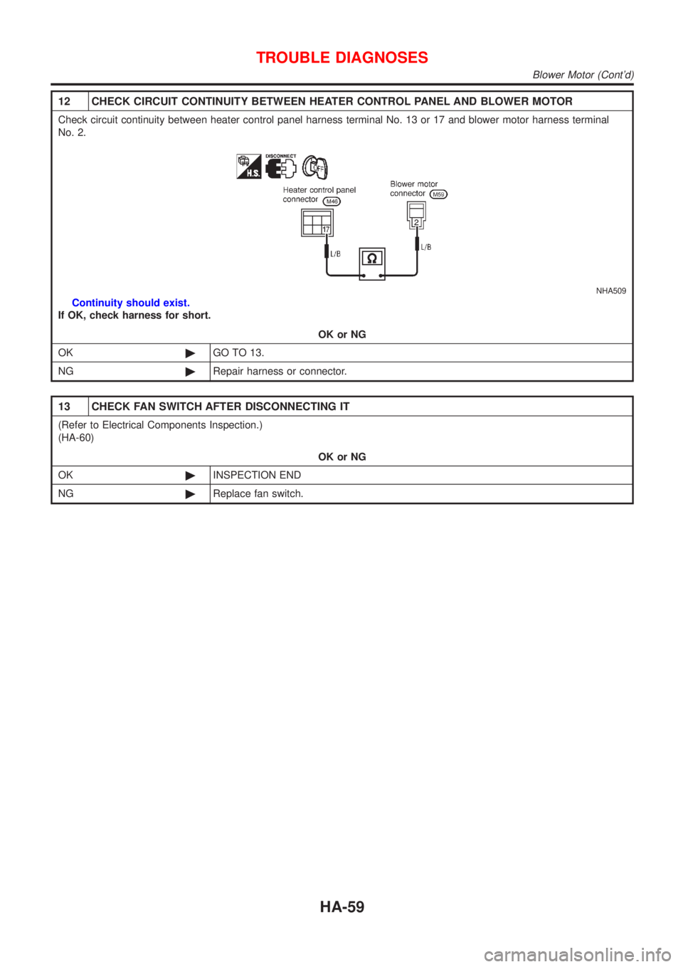
12 CHECK CIRCUIT CONTINUITY BETWEEN HEATER CONTROL PANEL AND BLOWER MOTOR
Check circuit continuity between heater control panel harness terminal No. 13 or 17 and blower motor harness terminal
No. 2.
NHA509
Continuity should exist.
If OK, check harness for short.
OK or NG
OK©GO TO 13.
NG©Repair harness or connector.
13 CHECK FAN SWITCH AFTER DISCONNECTING IT
(Refer to Electrical Components Inspection.)
(HA-60)
OK or NG
OK©INSPECTION END
NG©Replace fan switch.
TROUBLE DIAGNOSES
Blower Motor (Cont'd)
HA-59