Page 868 of 2493

SEF594K
DescriptionNJEC0649The engine coolant temperature sensor is used to detect the
engine coolant temperature. The sensor modifies a voltage signal
from the ECM. The modified signal returns to the ECM as the
engine coolant temperature input. The sensor uses a thermistor
which is sensitive to the change in temperature. The electrical
resistance of the thermistor decreases as temperature increases.
SEF012P
Engine coolant tempera-
ture ÉC (ÉF)Voltage* (V) Resistance (kW)
þ10 (14) 4.4 7.0 - 11.4
20 (68) 3.5 2.1 - 2.9
50 (122) 2.3 0.68 - 1.00
90 (194) 1.0 0.236 - 0.260
*: These data are reference values and measured between ECM terminal 347
(Engine coolant temperature sensor) and ground.
CAUTION:
Do not use ECM ground terminals when measuring input/
output voltage. Doing so may result in damage to the ECM's
transistor. Use a ground other than ECM terminals, such as
the ground.
On Board Diagnosis LogicNJEC0650
DTC Malfunction is detected when ... Check Items (Possible Cause)
P0115
0103+An excessively high or low voltage from the sen-
sor is entered to ECM.+Harness or connectors (The sensor circuit is
open or shorted.)
+Engine coolant temperature sensor
SEF817Y
DTC Confirmation ProcedureNJEC0651WITH CONSULT-IINJEC0651S011) Turn ignition switch ªONº.
2) Select ªDATA MONITORº mode with CONSULT-II.
3) Wait at least 5 seconds.
4) If DTC is detected, go to ªDiagnostic Procedureº, EC-575.
WITHOUT CONSULT-IINJEC0651S021) Turn ignition switch ªONº and wait at least 5 seconds.
2) Turn ignition switch ªOFFº, wait at least 5 seconds and then
turn ªONº.
DTC P0115 COOLANT TEMP SENYD
Description
EC-572
Page 969 of 2493
2 CHECK BATTERY AND ALTERNATOR
Check that the proper type of battery and alternator is installed.
Refer to SC-34, ªBatteryº and SC-35, ªAlternatorº.
OK or NG
OK©GO TO 5.
NG©Replace with a proper one.
3 CHECK JUMPER CABLES INSTALLATION
Check that the jumper cables are connected in the correct sequence.
SEF439Z
OK or NG
OK©GO TO 4.
NG©Reconnect jumper cables properly.
4 CHECK BATTERY FOR BOOSTER
Check that the battery for the booster is a 12V battery.
OK or NG
OK©GO TO 5.
NG©Change the vehicle for booster.
5 PERFORM DTC CONFIRMATION PROCEDURE AGAIN
Perform ªDTC Confirmation Procedureº, EC-672, again.
OK or NG
OK©GO TO 6.
NG©Replace ECM.
6 CHECK ELECTRICAL PARTS DAMAGE
Check the following for damage.
+Wiring harness and harness connectors for burn
+Fuses for short
OK or NG
OK©INSPECTION END
NG©Repair or replace malfunctioning part.
DTC P1660 BATTERY VOLTAGEYD
Diagnostic Procedure (Cont'd)
EC-673
Page 982 of 2493

DescriptionNJEC0764SYSTEM DESCRIPTIONNJEC0764S01
Sensor Input Signal to ECM ECM Function Actuator
Electronic controlled fuel injection pump Fuel injection signal
EGR volume con-
trolEGR volume control
valve Crankshaft position sensor (TDC) Engine speed
Vehicle speed sensor Vehicle speed
Engine coolant temperature sensor Engine coolant temperature
Ignition switch Start signal
Accelerator position sensor Accelerator position
Mass air flow sensor Amount of intake air
Air conditioner switch Air conditioner operation
Electrical load Electrical load signal
This system controls flow rate of EGR led from exhaust manifold
to intake manifold. The opening of the EGR by-pass passage in the
EGR volume control valve changes to control the flow rate. A
built-in step motor moves the valve in steps corresponding to the
ECM output pulses. The opening of the valve varies for optimum
engine control. The optimum value stored in the ECM is determined
by considering various engine conditions.
The EGR volume control valve remains close under the following
conditions.
+Engine stopped
+Engine starting
+Low engine coolant temperature
+Excessively high engine coolant temperature
+High engine speed
+Wide open throttle
SEF908Y
SEF411Y
COMPONENT DESCRIPTIONNJEC0764S02EGR Volume Control ValveNJEC0764S0201The EGR volume control valve uses a step motor to control the flow
rate of EGR from exhaust manifold. This motor has four winding
phases. It operates according to the output pulse signal of the
ECM. Two windings are turned ON and OFF in sequence. Each
time an ON pulse is issued, the valve opens or closes, changing
the flow rate. When no change in the flow rate is needed, the ECM
does not issue the pulse signal. A certain voltage signal is issued
so that the valve remains at that particular opening.
EGR VOLUME CONTROL SYSTEMYD
Description
EC-686
Page 1005 of 2493
SFE639A
SFE640A
7. Disconnect electrical connector.
8. Disconnect the quick connector as follows.
a. Put mating marks on tubes and connectors for correct instal-
lation.
SFE562A
b. Hold the connector while pushing in tabs, and pull out the tube.
CAUTION:
+The tube can be removed when the tabs are completely
depressed. Do not twist it more than necessary.
+Do not use any tools to remove the quick connector.
+Keep the resin tube away from heat. Be especially careful
when welding near the tube.
+Prevent acid liquid such as battery electrolyte etc. from
getting on the resin tube.
+Do not bend or twist the tube during installation and
removal.
SFE650A
9. From rear left area of fuel tank, remove filler hose, vent hose,
and EVAP hose.
CAUTION:
To prevent fuel from flowing out, install a blind cap immedi-
ately after the fuel hose is disconnected.
SFE642A
10. Remove exhaust center tube.
FUEL SYSTEMQG
Fuel Tank (Cont'd)
FE-7
Page 1007 of 2493
Fuel Pump, Fuel Level Sensor Unit and Fuel
Filter
NJFE0007
NFE065
JFE613A
REMOVALNJFE0007S011. Release fuel pressure from fuel line.
Refer to EC-38, ªFuel Pressure Releaseº.
2. Disconnect battery ground cable.
3. Open fuel filler lid and filler cap.
4. Remove rear seat cushion. Refer to BT-59, ªRemoval and
Installationº.
5. Remove inspection hole cover under the rear seat.
SFE639A
6. Disconnect electrical connector.
7. Disconnect the quick connectors.
+For disconnect of quick connectors, refer to step 8. of ªFuel
Tank Removalº.
FUEL SYSTEMQG
Fuel Pump, Fuel Level Sensor Unit and Fuel Filter
FE-9
Page 1018 of 2493

JFE613A
SFE600A
SFE601A
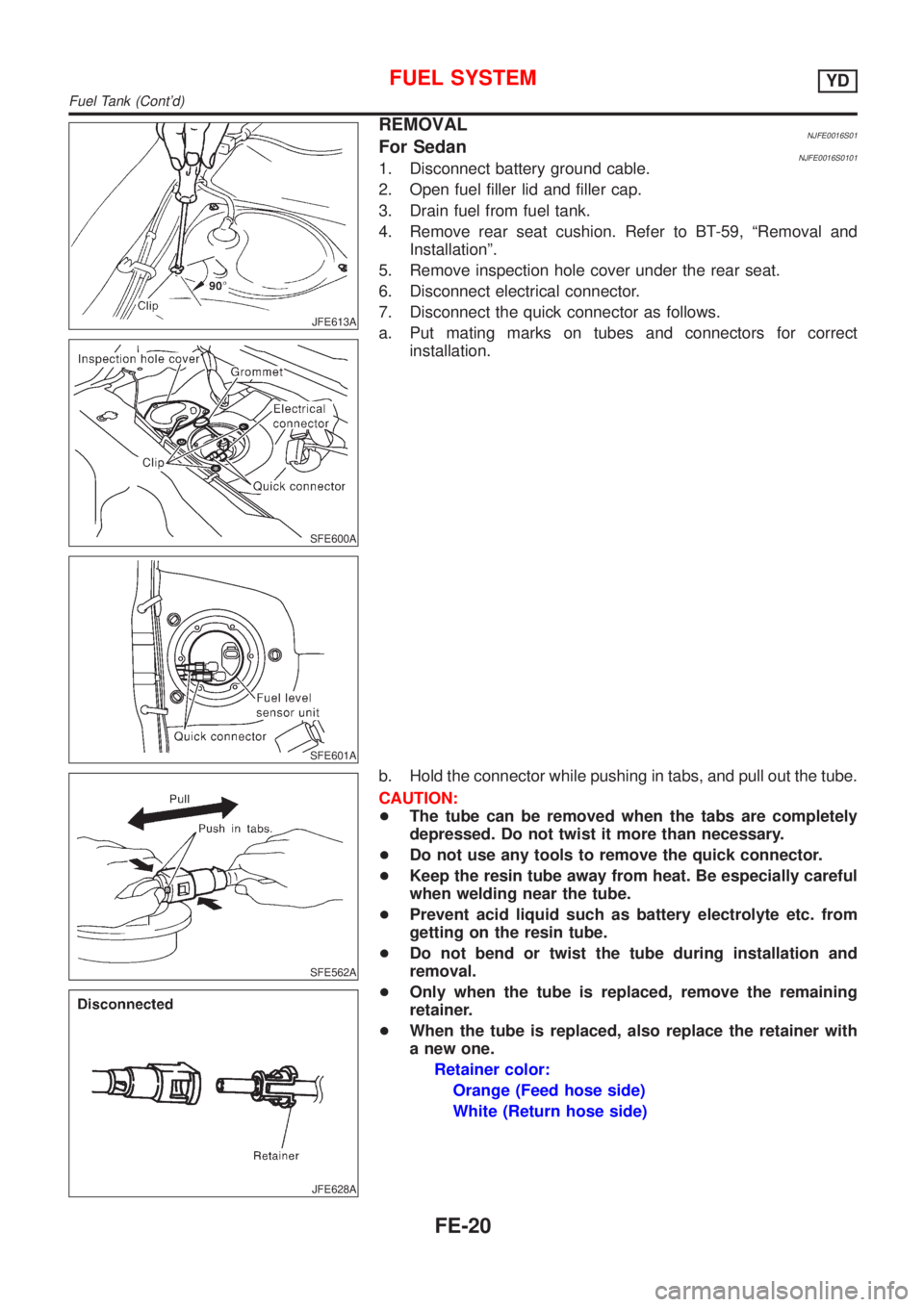
REMOVALNJFE0016S01For SedanNJFE0016S01011. Disconnect battery ground cable.
2. Open fuel filler lid and filler cap.
3. Drain fuel from fuel tank.
4. Remove rear seat cushion. Refer to BT-59, ªRemoval and
Installationº.
5. Remove inspection hole cover under the rear seat.
6. Disconnect electrical connector.
7. Disconnect the quick connector as follows.
a. Put mating marks on tubes and connectors for correct
installation.
SFE562A
JFE628A
b. Hold the connector while pushing in tabs, and pull out the tube.
CAUTION:
+The tube can be removed when the tabs are completely
depressed. Do not twist it more than necessary.
+Do not use any tools to remove the quick connector.
+Keep the resin tube away from heat. Be especially careful
when welding near the tube.
+Prevent acid liquid such as battery electrolyte etc. from
getting on the resin tube.
+Do not bend or twist the tube during installation and
removal.
+Only when the tube is replaced, remove the remaining
retainer.
+When the tube is replaced, also replace the retainer with
a new one.
Retainer color:
Orange (Feed hose side)
White (Return hose side)
FUEL SYSTEMYD
Fuel Tank (Cont'd)
FE-20
Page 1020 of 2493

JFE613A
SFE639A
SFE640A
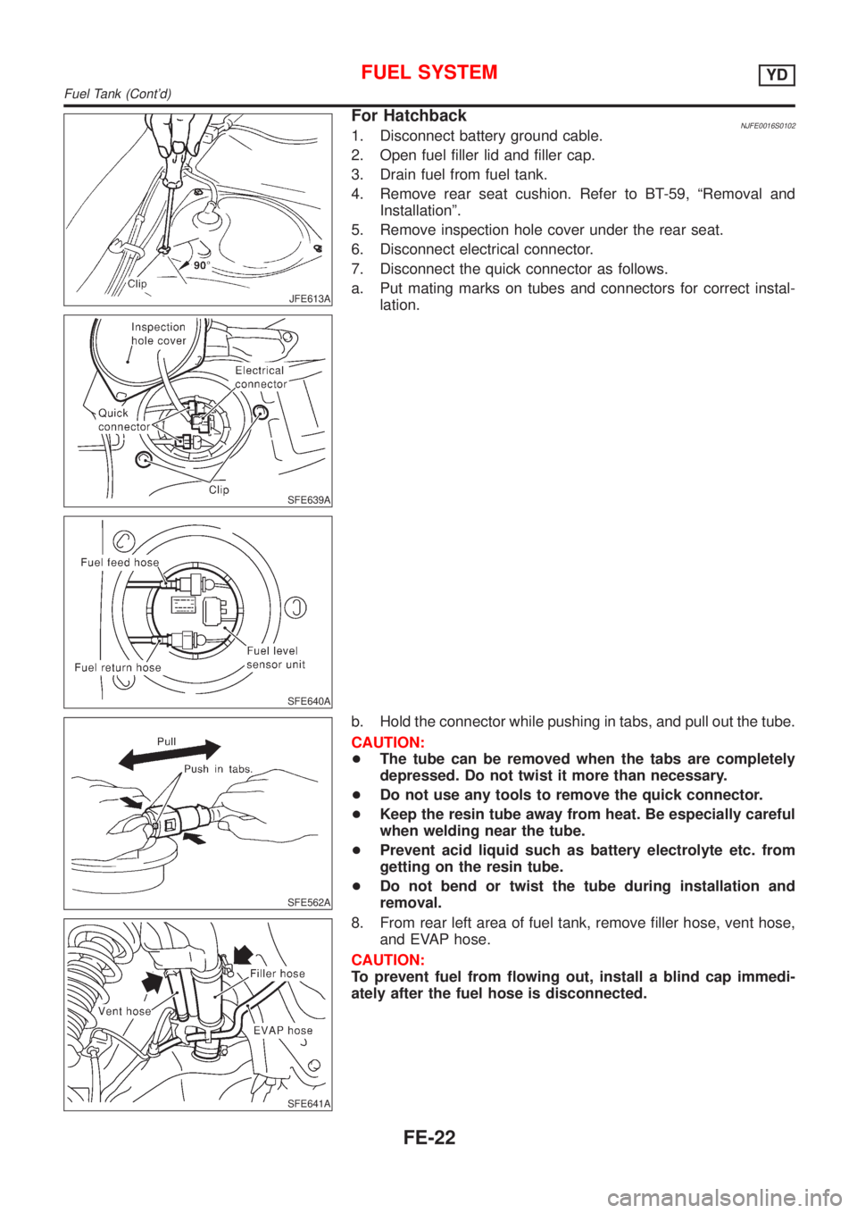
For HatchbackNJFE0016S01021. Disconnect battery ground cable.
2. Open fuel filler lid and filler cap.
3. Drain fuel from fuel tank.
4. Remove rear seat cushion. Refer to BT-59, ªRemoval and
Installationº.
5. Remove inspection hole cover under the rear seat.
6. Disconnect electrical connector.
7. Disconnect the quick connector as follows.
a. Put mating marks on tubes and connectors for correct instal-
lation.
SFE562A
b. Hold the connector while pushing in tabs, and pull out the tube.
CAUTION:
+The tube can be removed when the tabs are completely
depressed. Do not twist it more than necessary.
+Do not use any tools to remove the quick connector.
+Keep the resin tube away from heat. Be especially careful
when welding near the tube.
+Prevent acid liquid such as battery electrolyte etc. from
getting on the resin tube.
+Do not bend or twist the tube during installation and
removal.
SFE641A
8. From rear left area of fuel tank, remove filler hose, vent hose,
and EVAP hose.
CAUTION:
To prevent fuel from flowing out, install a blind cap immedi-
ately after the fuel hose is disconnected.
FUEL SYSTEMYD
Fuel Tank (Cont'd)
FE-22
Page 1023 of 2493

JFE613A
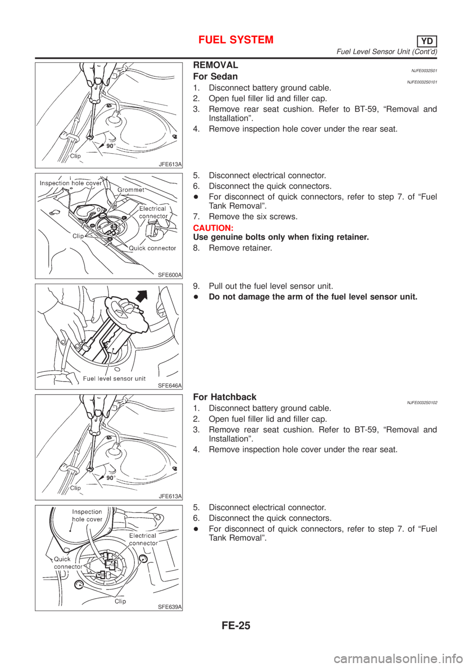
REMOVALNJFE0032S01For SedanNJFE0032S01011. Disconnect battery ground cable.
2. Open fuel filler lid and filler cap.
3. Remove rear seat cushion. Refer to BT-59, ªRemoval and
Installationº.
4. Remove inspection hole cover under the rear seat.
SFE600A
5. Disconnect electrical connector.
6. Disconnect the quick connectors.
+For disconnect of quick connectors, refer to step 7. of ªFuel
Tank Removalº.
7. Remove the six screws.
CAUTION:
Use genuine bolts only when fixing retainer.
8. Remove retainer.
SFE646A
9. Pull out the fuel level sensor unit.
+Do not damage the arm of the fuel level sensor unit.
JFE613A
For HatchbackNJFE0032S01021. Disconnect battery ground cable.
2. Open fuel filler lid and filler cap.
3. Remove rear seat cushion. Refer to BT-59, ªRemoval and
Installationº.
4. Remove inspection hole cover under the rear seat.
SFE639A
5. Disconnect electrical connector.
6. Disconnect the quick connectors.
+For disconnect of quick connectors, refer to step 7. of ªFuel
Tank Removalº.
FUEL SYSTEMYD
Fuel Level Sensor Unit (Cont'd)
FE-25