2001 NISSAN ALMERA N16 front turn
[x] Cancel search: front turnPage 58 of 2493

NJMA0036
Shown below are Pre-delivery Inspection Items required for the new vehicle. It is recommended that
necessary items other than those listed here be added, paying due regard to the conditions in each
country.
Perform applicable items on each model. Consult text of this section for specifications.
UNDER HOOD Ð engine off
Radiator coolant level and coolant hose connections for leaks
Battery fluid level, specific gravity and conditions of battery terminals
Drive belts tension
Fuel filter for water or dusts (Diesel only), and fuel lines and connections for leaks
Engine oil level and oil leaks
Clutch and brake reservoir fluid level and fluid lines for leaks
Windshield and rear window washer and headlamp cleaner reservoir fluid level
Power steering reservoir fluid level and hose connections for leaks
ON INSIDE AND OUTSIDE
Remove front spring/strut spacer (If applicable)
Operation of all instruments, gauges, lights and accessories
Operation of horn(s), wiper and washer
Steering lock for operation
Check air conditioner for gas leaks
Front and rear seats, and seat belts for operation
All moldings, trims and fittings for fit and alignment
All windows for operation and alignment
Hood, trunk lid, door panels for fit and alignment
Latches, keys and locks for operation
Weatherstrips for adhesion and fit
Headlamp aiming
Tighten wheel nuts (Inc. inner nuts if applicable)
Tire pressure (Inc. spare tire)
Check front wheels for toe-in
Install clock/voltmeter/room lamp fuse (If applicable)
Install deodorizing filter to air conditioner (If applicable)
Remove wiper blade protectors (If applicable)
UNDER BODY
Manual transmission/transaxle, transfer and differential gear oil level
Brake and fuel lines and oil/fluid reservoirs for leaks
Tighten bolts and nuts of steering linkage and gear box, suspension, propeller shafts and drive shafts
Tighten rear body bolts and nuts (Models with wooden bed only)
ROAD TEST
Clutch operation
Parking brake operation
Service brake operation
Automatic transmission/transaxle shift timing and kickdown
Steering control and returnability
Engine performance
Squeaks and rattles
ENGINE OPERATING AND HOT
Adjust idle speed
Automatic transmission/transaxle fluid level
Engine idling and stop knob operation (Diesel only)
FINAL INSPECTION
Install necessary parts (outside mirror, wheel covers, seat belts, mat, carpet or mud flaps)
Inspect for interior and exterior metal and paint damage
Check for spare tire, jack, tools (wheel chock), and literature
Wash, clean interior and exterior
: Not applicable to this model
PRE-DELIVERY INSPECTION ITEMS
MA-2
Page 101 of 2493
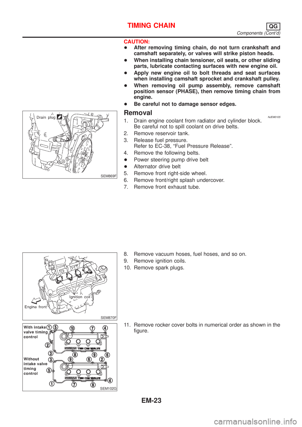
CAUTION:
+After removing timing chain, do not turn crankshaft and
camshaft separately, or valves will strike piston heads.
+When installing chain tensioner, oil seats, or other sliding
parts, lubricate contacting surfaces with new engine oil.
+Apply new engine oil to bolt threads and seat surfaces
when installing camshaft sprocket and crankshaft pulley.
+When removing oil pump assembly, remove camshaft
position sensor (PHASE), then remove timing chain from
engine.
+Be careful not to damage sensor edges.
SEM869F
RemovalNJEM01051. Drain engine coolant from radiator and cylinder block.
Be careful not to spill coolant on drive belts.
2. Remove reservoir tank.
3. Release fuel pressure.
Refer to EC-38, ªFuel Pressure Releaseº.
4. Remove the following belts.
+Power steering pump drive belt
+Alternator drive belt
5. Remove front right-side wheel.
6. Remove front/right splash undercover.
7. Remove front exhaust tube.
SEM870F
8. Remove vacuum hoses, fuel hoses, and so on.
9. Remove ignition coils.
10. Remove spark plugs.
SEM102G
11. Remove rocker cover bolts in numerical order as shown in the
figure.
TIMING CHAINQG
Components (Cont'd)
EM-23
Page 140 of 2493

SEM933F
3. Install crankshaft and main bearing caps and tighten bolts to
the specified torque.
+Apply new engine oil to the bolt thread and seat surface.
+Prior to tightening bearing cap bolts, shift crankshaft back
and forth to properly seat the bearing caps.
+Tighten bearing cap bolts gradually in two or three stages.
Start with center bearing and move outward as shown in
figure.
+After securing bearing cap bolts, make sure crankshaft
turns smoothly by hand.
SEM116F
4. Measure crankshaft end play.
Crankshaft end play:
Standard
0.060 - 0.260 mm (0.0024 - 0.0102 in)
Limit
0.3 mm (0.012 in)
If beyond the limit, replace thrust bearing with new ones.
SEM168D
5. Install connecting rod bearings in connecting rods and con-
necting rod caps.
+Confirm that correct bearings are used. Refer to EM-58.
+Install bearings so that oil hole in connecting rod aligns
with oil hole of bearing.
+Apply new engine oil to bolt threads and bearing surfaces.
SEM942F
6. Install pistons with connecting rods.
a. Install them into corresponding cylinders with Tool.
+Make sure connecting rod does not scratch cylinder wall.
+Make sure connecting rod bolts do not scratch crankshaft
pin journals.
+Arrange so that front mark on piston head faces engine.
+Apply new engine oil to piston rings and sliding surface
of piston.
SEM943F
b. Install connecting rod caps.
Apply new engine oil to bolt threads and nut seating surfaces.
Tighten connecting rod cap nuts in the following procedure:
+Tighten to 13.72 to 15.68 N´m (1.399 to 1.599 kg-m, 10.120
to 11.566 ft-lb).
+Turn nuts to 35É to 40É degrees clockwise with an angle
wrench. If an angle wrench is not available, tighten nuts to
23 to 28 N´m (2.3 to 2.9 kg-m, 17 to 21 ft-lb).
CYLINDER BLOCKQG
Assembly (Cont'd)
EM-62
Page 163 of 2493

+If the belt deflection of the current belt is out of the ªLimit
for re-tighteningº, adjust to the ªAdjusted valueº.
+When checking belt deflection immediately after
installation, first adjust it to the specified value. Then,
after turning crankshaft two turns or more, re-adjust it to
the specified value to avoid variation in deflection
between pulleys.
+Make sure the belts are fully fitted into the pulley grooves
during installation.
+Handle with care to avoid smearing the belts with oil or
cooling water etc.
+Do not twist or bend the belts with strong force.
JEM251G
AIR CONDITIONER COMPRESSOR BELTNJEM0089S011. Remove RH splash cover (with undercover attached).
2. Loosen idler pulley lock nut (A).
3. Turn adjusting bolt (B) to adjust.
+Refer to EM-84, ªInspectionº for adjustment values.
4. Tighten lock nut (A).
Nut A:
: 31 - 39 N´m (3.1 - 4.0 kg-m, 23 - 28 ft-lb)
ALTERNATOR & WATER PUMP BELTNJEM0089S021. Loosen adjuster lock nut (C).
2. Loosen alternator fixing bolts (D) (each on front and rear).
3. Turn adjusting bolt (E) to adjust.
+Refer to EM-84, ªInspectionº for adjustment values.
4. Tighten nut (C) and bolt (D) in this order.
Nut C:
: 19 - 24 N´m (1.9 - 2.5 kg-m, 14 - 18 ft-lb)
Bolt D:
: 44 - 57 N´m (4.4 - 5.9 kg-m, 32 - 42 ft-lb)
RemovalNJEM00901. Loosen each belt. Refer to EM-84, ªAdjustmentº.
2. Remove air conditioner compressor belt.
3. Remove alternator & water pump belt.
DRIVE BELTSYD
Adjustment (Cont'd)
EM-85
Page 172 of 2493

JEM121G
3. Remove front chain case.
+Move power steering fluid reservoir tank from the bracket.
+Loosen fixing bolts in the reverse order of that shown in the
figure and remove them.
+Remove No. 6, 10, and 11 bolts with the rubber washer as
space is limited for pulling them out.
SEM514G
CAUTION:
+While front chain case is removed, cover openings to pre-
vent entry of foreign material into engine.
+Do not remove two mass dampers on the back of cover.
SEM515G
4. Set the No. 1 piston to TDC on its compression stroke.
+Turn crankshaft pulley clockwise so that the alignment mark
(punched mark) on each camshaft sprocket is positioned as
shown in the figure.
+No position indicator is provided on the crankshaft pulley.
+When installing, color coded links on the secondary tim-
ing chain can be used as alignment marks. Marking may
not be necessary for removal; however, make alignment
marks as required because the alignment mark on fuel
injection pump sprocket may not be easy to see.
JEM124G
5. Remove chain tensioner.
a. Push the plunger of chain tensioner and keep it pressed with
a push pin.
JEM125G
b. Using a hexagon-head wrench (face to face: 5 mm, SST),
remove bolts to remove chain tensioner.
TIMING CHAINYD
Secondary Timing Chain (Cont'd)
EM-94
Page 181 of 2493
JEM137G
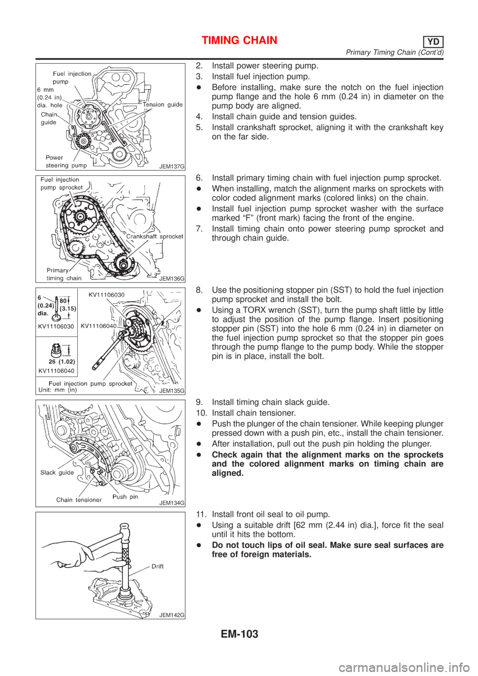
2. Install power steering pump.
3. Install fuel injection pump.
+Before installing, make sure the notch on the fuel injection
pump flange and the hole 6 mm (0.24 in) in diameter on the
pump body are aligned.
4. Install chain guide and tension guides.
5. Install crankshaft sprocket, aligning it with the crankshaft key
on the far side.
JEM136G
6. Install primary timing chain with fuel injection pump sprocket.
+When installing, match the alignment marks on sprockets with
color coded alignment marks (colored links) on the chain.
+Install fuel injection pump sprocket washer with the surface
marked ªFº (front mark) facing the front of the engine.
7. Install timing chain onto power steering pump sprocket and
through chain guide.
JEM135G
8. Use the positioning stopper pin (SST) to hold the fuel injection
pump sprocket and install the bolt.
+Using a TORX wrench (SST), turn the pump shaft little by little
to adjust the position of the pump flange. Insert positioning
stopper pin (SST) into the hole 6 mm (0.24 in) in diameter on
the fuel injection pump sprocket so that the stopper pin goes
through the pump flange to the pump body. While the stopper
pin is in place, install the bolt.
JEM134G
9. Install timing chain slack guide.
10. Install chain tensioner.
+Push the plunger of the chain tensioner. While keeping plunger
pressed down with a push pin, etc., install the chain tensioner.
+After installation, pull out the push pin holding the plunger.
+Check again that the alignment marks on the sprockets
and the colored alignment marks on timing chain are
aligned.
JEM142G
11. Install front oil seal to oil pump.
+Using a suitable drift [62 mm (2.44 in) dia.], force fit the seal
until it hits the bottom.
+Do not touch lips of oil seal. Make sure seal surfaces are
free of foreign materials.
TIMING CHAINYD
Primary Timing Chain (Cont'd)
EM-103
Page 207 of 2493
Installation=NJEM0067+Before installation, remove old liquid gasket from mating
surface of all liquid gasket applied parts.
SEM505G
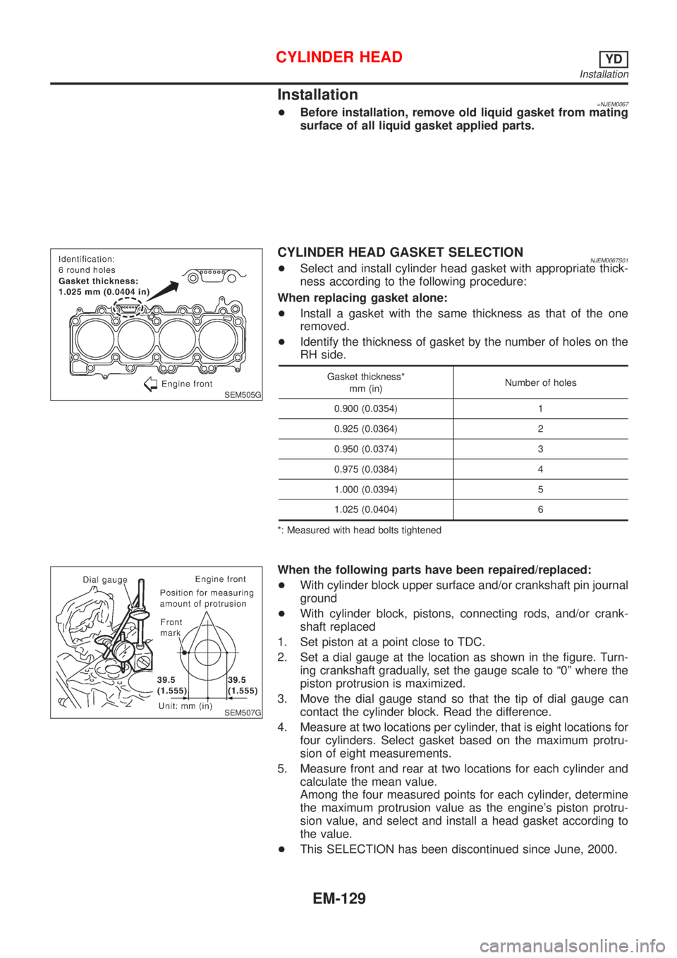
CYLINDER HEAD GASKET SELECTIONNJEM0067S01+Select and install cylinder head gasket with appropriate thick-
ness according to the following procedure:
When replacing gasket alone:
+Install a gasket with the same thickness as that of the one
removed.
+Identify the thickness of gasket by the number of holes on the
RH side.
Gasket thickness*
mm (in)Number of holes
0.900 (0.0354) 1
0.925 (0.0364) 2
0.950 (0.0374) 3
0.975 (0.0384) 4
1.000 (0.0394) 5
1.025 (0.0404) 6
*: Measured with head bolts tightened
SEM507G
When the following parts have been repaired/replaced:
+With cylinder block upper surface and/or crankshaft pin journal
ground
+With cylinder block, pistons, connecting rods, and/or crank-
shaft replaced
1. Set piston at a point close to TDC.
2. Set a dial gauge at the location as shown in the figure. Turn-
ing crankshaft gradually, set the gauge scale to ª0º where the
piston protrusion is maximized.
3. Move the dial gauge stand so that the tip of dial gauge can
contact the cylinder block. Read the difference.
4. Measure at two locations per cylinder, that is eight locations for
four cylinders. Select gasket based on the maximum protru-
sion of eight measurements.
5. Measure front and rear at two locations for each cylinder and
calculate the mean value.
Among the four measured points for each cylinder, determine
the maximum protrusion value as the engine's piston protru-
sion value, and select and install a head gasket according to
the value.
+This SELECTION has been discontinued since June, 2000.
CYLINDER HEADYD
Installation
EM-129
Page 210 of 2493

JEM175G
3. Install camshaft brackets.
+Install correctly, identifying brackets by the journal No. and
front mark on top surface.
JEM160G
4. Tighten bolts in the order shown in the figure according to the
following procedure:
a. Tighten to 2.0 N´m (0.2 kg-m, 17 in-lb).
+Make sure camshaft thrusting parts (on rear side) securely fit
in their mating parts on the cylinder head.
b. Tighten to 6 N´m (0.6 kg-m, 52 in-lb).
c. Tighten to 12 to 13 N´m (1.2 to 1.4 kg-m, 9 to 10 ft-lb).
5. Install camshaft sprockets.
+Camshaft sprockets are commonly used for RH and LH.
+Align camshaft sprocket and dowel pin on camshaft, and
install.
+Holding the hexagonal part of camshaft with a wrench, tighten
bolt securing camshaft sprocket.
6. Before installing spill tube after installing secondary timing
chain, check and adjust valve clearance. Refer to EM-132,
ªValve Clearanceº.
7. Hereafter, install in the reverse order of removal.
JEM176G
Valve ClearanceNJEM0068CHECKINGNJEM0068S01Check valve clearance while engine is cold and not running.
1. Set the No. 1 piston to TDC on its compression stroke.
+Turn crankshaft pulley clockwise so that the knock pin on cam-
shaft LH faces straight above. (No position indicator, etc. is
provided on the crankshaft pulley.)
JEM177G
2. Put an alignment mark with paint, etc. on the crankshaft pul-
ley and on the oil pump as an angle indicator.
CYLINDER HEADYD
Installation (Cont'd)
EM-132