2001 NISSAN ALMERA N16 EL-89
[x] Cancel search: EL-89Page 608 of 2493

Diagnostic ProcedureNJEC0278
1 CHECK INPUT SIGNAL CIRCUIT
1. Turn ignition switch ªOFFº.
2. Disconnect ECM harness connector and combination meter harness connector.
3. Check harness continuity between ECM terminal 86 and meter terminal 4.
Refer to wiring diagram.
Continuity should exist.
4. Also check harness for short to ground and short to power.
OK or NG
OK©GO TO 3.
NG©GO TO 2.
2 DETECT MALFUNCTIONING PART
Check the following.
+Harness connectors M63, F102
+Harness for open or short between ECM and combination meter
©Repair open circuit or short to ground or short to power in harness or connectors.
3 CHECK SPEEDOMETER FUNCTION
Make sure that speedometer functions properly.
OK or NG
OK©GO TO 5.
NG©GO TO 4.
4 CHECK SPEEDOMETER CIRCUIT
Check the following.
+Harness connectors M63, F102
+Harness connectors M169, F113
+Harness for open or short between combination meter and vehicle speed sensor
OK©Check combination meter and vehicle speed sensor. Refer to EL-89, ªMETERS AND
GAUGESº.
NG©Repair open circuit or short to ground or short to power in harness or connectors.
5 CHECK INTERMITTENT INCIDENT
Perform ªTROUBLE DIAGNOSIS FOR INTERMITTENT INCIDENTº, EC-144.
©INSPECTION END
DTC P0500 VEHICLE SPEED SENSOR (VSS)QG
Diagnostic Procedure
EC-312
Page 978 of 2493

6 CHECK GLOW INDICATOR LAMP POWER SUPPLY CIRCUIT
1. Turn ignition switch ªOFFº.
2. Disconnect combination meter harness connector M32 or M152 or M171.
3. Turn ignition switch ªONº.
4. Check voltage between combination meter terminal 40 or 17 or 1 and ground with CONSULT-II or tester.
YEC060A
OK or NG
OK©GO TO 8.
NG©GO TO 7.
7 DETECT MALFUNCTIONING PART
Check the following.
1. Fuse block (J/B) connector M1
2. 10A fuse
3. Harness for open or short between combination meter and fuse
©Repair open circuit or short to ground or short to power in harness or connectors.
8 CHECK GLOW INDICATOR LAMP OUTPUT SIGNAL CIRCUIT FOR OPEN AND SHORT
1. Turn ignition switch ªOFFº.
2. Disconnect ECM harness connector.
3. Disconnect combination meter harness connector M171.
4. Check harness continuity between ECM terminal 508 and combination meter terminal 17. Refer to Wiring Diagram.
Continuity should exist.
5. Also check harness for short to ground and short to power.
OK or NG
OK©GO TO 10.
NG©GO TO 9.
9 DETECT MALFUNCTIONING PART
Check the following.
1. Harness connectors M63, F102
2. Harness for open or short between combination meter and ECM
©Repair open circuit or short to ground or short to power in harness or connectors.
10 CHECK COMBINATION METER
Check combination meter and glow indicator lamp. Refer to EL-89, ªMeter and Gaugesº.
OK or NG
OK©GO TO 18.
NG©Repair or replace combination meter or glow indicator lamp.
GLOW CONTROL SYSTEMYD
Diagnostic Procedure (Cont'd)
EC-682
Page 1317 of 2493
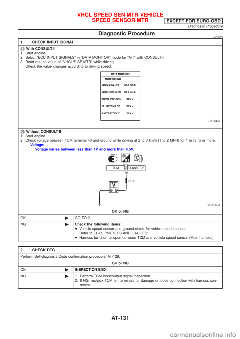
Diagnostic ProcedureNJAT0080
1 CHECK INPUT SIGNAL
With CONSULT-II
1. Start engine.
2. Select ªECU INPUT SIGNALSº in ªDATA MONITORº mode for ªA/Tº with CONSULT-II.
3. Read out the value of ªVHCL/S SE´MTRº while driving.
Check the value changes according to driving speed.
SAT614J
Without CONSULT-II
1. Start engine.
2. Check voltage between TCM terminal 40 and ground while driving at 2 to 3 km/h (1 to 2 MPH) for1m(3ft)ormore.
Voltage:
Voltage varies between less than 1V and more than 4.5V.
SAT465JA
OK or NG
OK©GO TO 2.
NG©Check the following items:
+Vehicle speed sensor and ground circuit for vehicle speed sensor
Refer to EL-89, ªMETERS AND GAUGESº.
+Harness for short or open between TCM and vehicle speed sensor (Main harness)
2 CHECK DTC
Perform Self-diagnosis Code confirmation procedure, AT-129.
OK or NG
OK©INSPECTION END
NG©1. Perform TCM input/output signal inspection.
2. If NG, recheck TCM pin terminals for damage or loose connection with harness con-
nector.
VHCL SPEED SEN´MTR VEHICLE
SPEED SENSOR´MTR
EXCEPT FOR EURO-OBD
Diagnostic Procedure
AT-131
Page 1467 of 2493
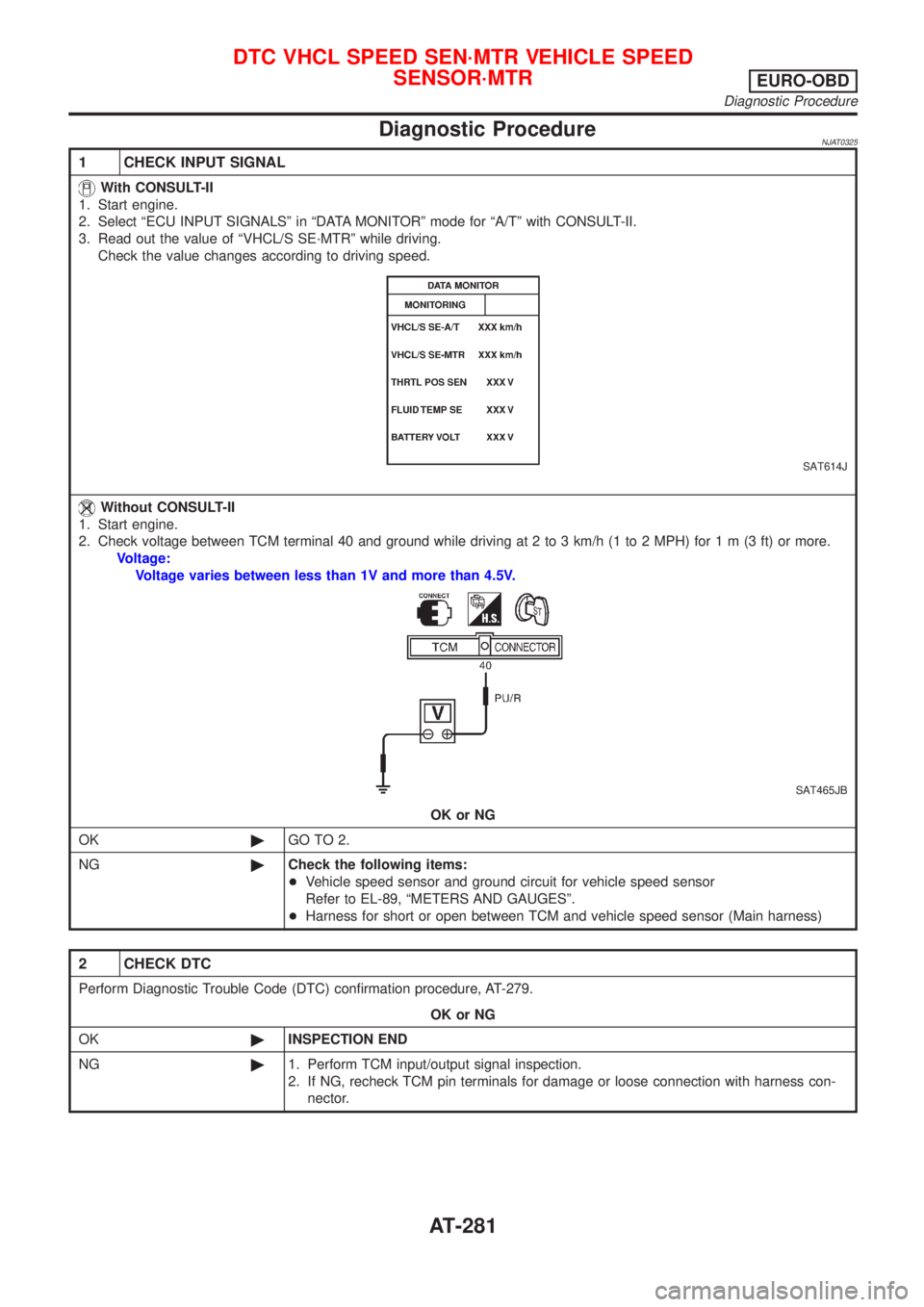
Diagnostic ProcedureNJAT0325
1 CHECK INPUT SIGNAL
With CONSULT-II
1. Start engine.
2. Select ªECU INPUT SIGNALSº in ªDATA MONITORº mode for ªA/Tº with CONSULT-II.
3. Read out the value of ªVHCL/S SE´MTRº while driving.
Check the value changes according to driving speed.
SAT614J
Without CONSULT-II
1. Start engine.
2. Check voltage between TCM terminal 40 and ground while driving at 2 to 3 km/h (1 to 2 MPH) for1m(3ft)ormore.
Voltage:
Voltage varies between less than 1V and more than 4.5V.
SAT465JB
OK or NG
OK©GO TO 2.
NG©Check the following items:
+Vehicle speed sensor and ground circuit for vehicle speed sensor
Refer to EL-89, ªMETERS AND GAUGESº.
+Harness for short or open between TCM and vehicle speed sensor (Main harness)
2 CHECK DTC
Perform Diagnostic Trouble Code (DTC) confirmation procedure, AT-279.
OK or NG
OK©INSPECTION END
NG©1. Perform TCM input/output signal inspection.
2. If NG, recheck TCM pin terminals for damage or loose connection with harness con-
nector.
DTC VHCL SPEED SEN´MTR VEHICLE SPEED
SENSOR´MTR
EURO-OBD
Diagnostic Procedure
AT-281
Page 1475 of 2493

2 CHECK TCM GROUND CIRCUIT
1. Turn ignition switch to ªOFFº position.
2. Disconnect TCM harness connector.
3. Check continuity between TCM terminals 25, 48 and ground.
SAT468J
Continuity should exist.
If OK, check harness for short to ground and short to power.
OK or NG
OK©GO TO 3.
NG©Repair open circuit or short to ground or short to power in harness or connectors. Refer
to ªWiring Diagram Ð AT Ð MAINº, AT-121.
3 CHECK LAMP CIRCUIT
1. Turn ignition switch to ªOFFº position.
2. Check resistance between TCM terminals 13 and 10.
Resistance: 50 - 100W
SAT469JB
3. Reinstall any part removed.
OK or NG
OK©GO TO 4.
NG©Check the following items:
+O/D OFF indicator lamp.
Refer to EL-89, ªMETERS AND GAUGESº.
+Harness and fuse for short or open between ignition switch and O/D OFF indicator
lamp (Main harness)
Refer to EL-10, ªPOWER SUPPLY ROUTINGº.
+Harness for short or open between O/D OFF indicator lamp and TCM.
TROUBLE DIAGNOSES FOR SYMPTOMS
1. O/D OFF Indicator Lamp Does Not Come On (Cont'd)
AT-289
Page 2201 of 2493
Component Parts and Harness Connector
Location
NJEL0441For details, refer to ªELECTRICAL UNIT LOCATIONº (EL-319) and
ªHARNESS LAYOUTº (EL-324).
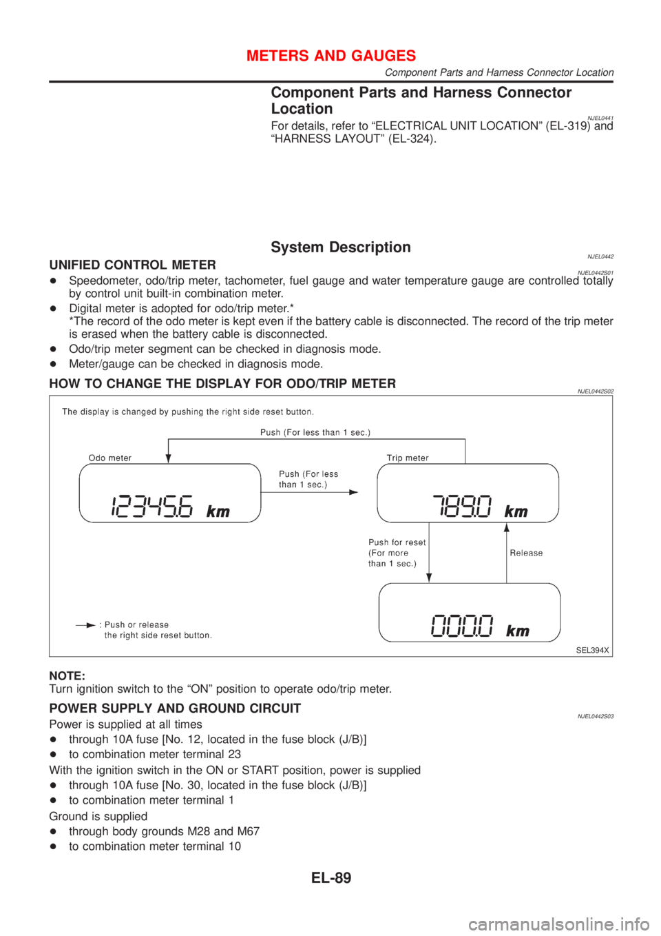
System DescriptionNJEL0442UNIFIED CONTROL METERNJEL0442S01+Speedometer, odo/trip meter, tachometer, fuel gauge and water temperature gauge are controlled totally
by control unit built-in combination meter.
+Digital meter is adopted for odo/trip meter.*
*The record of the odo meter is kept even if the battery cable is disconnected. The record of the trip meter
is erased when the battery cable is disconnected.
+Odo/trip meter segment can be checked in diagnosis mode.
+Meter/gauge can be checked in diagnosis mode.
HOW TO CHANGE THE DISPLAY FOR ODO/TRIP METERNJEL0442S02
SEL394X
NOTE:
Turn ignition switch to the ªONº position to operate odo/trip meter.
POWER SUPPLY AND GROUND CIRCUITNJEL0442S03Power is supplied at all times
+through 10A fuse [No. 12, located in the fuse block (J/B)]
+to combination meter terminal 23
With the ignition switch in the ON or START position, power is supplied
+through 10A fuse [No. 30, located in the fuse block (J/B)]
+to combination meter terminal 1
Ground is supplied
+through body grounds M28 and M67
+to combination meter terminal 10
METERS AND GAUGES
Component Parts and Harness Connector Location
EL-89
Page 2483 of 2493
CONSULT for ABS .................................... BR-58
CONSULT for engine ........................ EC-81, 527
COOL/F - Wiring diagram ............... EC-337, 618
Camshaft inspection ......................... EM-36, 122
Camshaft position sensor (CMPS) ......... EC-278
Camshaft position sensor (PHASE) ........ EC-278
Canister - See EVAP canister ................... EC-33
Charging system ....................................... SC-24
Cigarette lighter ....................................... EL-136
Circuit breaker ........................................... EL-22
Closed throttle position switch ....... EC-321, 426
Clutch cover .............................................. CL-22
Clutch disc ................................................. CL-22
Clutch master cylinder ............................... CL-11
Clutch operating cylinder ........................... CL-14
Clutch pedal .............................................. CL-10
Clutch release bearing ........................ CL-17, 20
Clutch release mechanism .................. CL-17, 20
Clutch withdrawal lever ....................... CL-17, 20
Coil spring (front) ........................................ SU-9
Coil spring (rear) ....................................... SU-21
Collision diagnosis .................................... RS-71
Combination lamp, rear, removal and
installation .............................................. BT-47
Combination meter removal and instal-
lation - See Instrument panel ................ BT-25
Combination meter .................................... EL-89
Combination switch ................................... EL-37
Compression pressure ............................. EM-82
Compressor clutch removal and
installation .............................................. HA-89
Compressor precaution ............................... HA-5
Compressor special service tool ................. HA-9
Connecting rod bearing clearance ... EM-58, 150
Connecting rod bushing clearance ... EM-59, 152
Connecting rod ................................. EM-55, 145
Console box - See Instrument panel ......... BT-25
Control lever (M/T) .................................... MT-29
Control valve (A/T) ................................... AT-375
Converter housing installation ................. AT-347
Coolant mixture ratio ................................ MA-22
Cooling circuit (engine) ....................... LC-12, 36
Cooling fan control system .................. LC-17, 42
Cooling fan control .......................... EC-334, 618
Cooling fan motor ................................... EC-346
Cooling fan relay ..................................... EC-345
Coupling sleeve (M/T) .................. MT-31, 55, 93
Crankcase emission control system -
See Positive crankcase ventilation ...... EC-37,
508
Crankcase ventilation system - See
Positive crankcase ventilation ....... EC-37, 508
Crankshaft position sensor (OBD) .. EC-272, 394
Crankshaft position sensor (POS) .. EC-272, 394
Crankshaft position sensor (TDC) .......... EC-587
Crankshaft ........................................ EM-57, 148
Cylinder block ................................... EM-52, 139
Cylinder head .................................... EM-33, 118D
DEF - Wiring diagram .............................. EL-140
DTC work support ..................................... EC-90
Data link connector for Consult ........ EC-38, 527
Daytime light system ................................. EL-44
Detonation sensor - See Knock
sensor .................................................. EC-268
Diagnosis sensor unit ............................... RS-26
Diagnostic trouble code (DTC) for
OBD system .................... EC-10, 70, 492, 522
Diagnostic trouble code (DTC) inspec-
tion priority chart .................................. EC-122
Differential gear (FF A/T) ......................... AT-424
Differential gear (FF M/T) ...... MT-31, 43, 55, 93,
107
Dimensions ................................................. GI-43
Dome light - See Interior lamp .................. EL-76
Door glass ................................................. BT-17
Door lock ................................................... BT-21
Door mirror ................................................ BT-72
Door trim .................................................... BT-39
Door, front .................................................. BT-16
Door, rear ................................................... BT-16
Drive plate runout ..................................... EM-60
Drive shaft (front) ...................................... AX-10
Dropping resistor (A/T) .................... AT-180, 243
Dual pressure switch ................................ HA-13
E
ECCS-D control module ........ EC-554, 604, 664,
666, 670, 672
ECM input/output signal ................. EC-132, 554
ECTS - Wiring diagram ................... EC-165, 572
EGR control valve ................................... EC-359
EGR temperature sensor ........................ EC-347
EGR volume control valve ...................... EC-686
EGR/TS - Wiring diagram ....................... EC-350
EGRC1 - Wiring diagram ....... EC-289, 357, 403,
688
EVAP canister purge volume control
solenoid valve ........................................ EC-34
EVAP canister purge volume control
valve ............................................ EC-304, 411
EVAP canister ........................................... EC-34
Electric sunroof ........................................ EL-165
Electrical diagnoses ................................... GI-21
Electrical ignition system .......................... EC-31
Electrical load signal circuit ..................... EC-480
Electrical unit ........................................... EL-371
Electrical units location ............................ EL-319
Electronic fuel injection pump ........ EC-513, 606,
612, 634, 640, 646, 652, 658, 674
Engine compartment ................................. BT-75
Engine control circuit diagram .......... EC-25, 502
Engine control component parts
location .......................................... EC-21, 499
ALPHABETICAL INDEX
IDX-3
Page 2484 of 2493
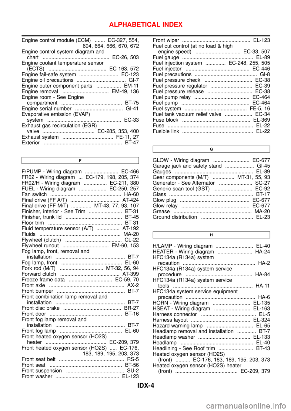
Engine control module (ECM) ....... EC-327, 554,
604, 664, 666, 670, 672
Engine control system diagram and
chart .............................................. EC-26, 503
Engine coolant temperature sensor
(ECTS) ........................................ EC-163, 572
Engine fail-safe system ........................... EC-123
Engine oil precautions .................................. GI-7
Engine outer component parts ................. EM-11
Engine removal ................................ EM-49, 136
Engine room - See Engine
compartment .......................................... BT-75
Engine serial number ................................. GI-41
Evaporative emission (EVAP)
system ................................................... EC-33
Exhaust gas recirculation (EGR)
valve .................................... EC-285, 353, 400
Exhaust system ................................... FE-11, 27
Exterior ...................................................... BT-47
F
F/PUMP - Wiring diagram ....................... EC-466
FR02 - Wiring diagram ... EC-179, 198, 205, 374
FR02/H - Wiring diagram ................ EC-211, 380
FUEL - Wiring diagram ................... EC-250, 257
Fan switch ................................................. HA-60
Final drive (FF A/T) .................................. AT-424
Final drive (FF M/T) .............. MT-43, 77, 93, 107
Finisher, interior - See Trim ....................... BT-31
Finisher, trunk lid ....................................... BT-45
Floor trim ................................................... BT-31
Fluid temperature sensor (A/T) ................ AT-192
Fluids ........................................................ MA-20
Flywheel (clutch) ....................................... CL-22
Flywheel runout ................................ EM-60, 153
Fog lamp, front, removal and
installation ................................................ BT-7
Fog lamp, front .......................................... EL-60
Fork rod (M/T) .............................. MT-32, 56, 94
Forward clutch ......................................... AT-399
Freeze frame data .............................. EC-59, 70
Front axle .................................................... AX-2
Front bumper ............................................... BT-7
Front combination lamp removal and
installation ................................................ BT-7
Front disc brake ........................................ BR-27
Front door .................................................. BT-16
Front fog lamp removal and
installation ................................................ BT-7
Front fog lamp ........................................... EL-60
Front heated oxygen sensor (HO2S)
heater .......................................... EC-209, 379
Front heated oxygen sensor (HO2S) ..... EC-176,
183, 189, 195, 203, 373
Front seat belt ............................................. RS-5
Front seat .................................................. BT-56
Front suspension ........................................ SU-2
Front washer ............................................ EL-123Front wiper ............................................... EL-123
Fuel cut control (at no load & high
engine speed) ............................... EC-33, 507
Fuel gauge ................................................. EL-89
Fuel injection system .............. EC-248, 255, 505
Fuel injector ............................................ EC-446
Fuel precautions ........................................... GI-8
Fuel pressure check ................................. EC-38
Fuel pressure regulator ............................. EC-39
Fuel pressure release ............................... EC-38
Fuel pump relay ...................................... EC-464
Fuel pump ............................................... EC-464
Fuel system ........................................... FE-5, 16
Fuel tank vacuum relief valve ................... EC-34
Fuse block ............................................... EL-369
Fuse ........................................................... EL-22
Fusible link ................................................. EL-22
G
GLOW - Wiring diagram ......................... EC-677
Garage jack and safety stand .................... GI-45
Gauges ...................................................... EL-89
Gear components (M/T) ............... MT-31, 55, 93
Generator - See Alternator ....................... SC-27
Generic scan tool (GST) ........................... EC-92
Glass .......................................................... BT-17
Glow plug ................................................ EC-677
Glow relay ............................................... EC-677
Grease ...................................................... MA-20
Ground distribution .................................... EL-23
H
H/LAMP - Wiring diagram .......................... EL-40
HEATER - Wiring diagram ........................ HA-24
HFC134a (R134a) system
recaution .................................................. HA-2
HFC134a (R134a) system service
procedure .............................................. HA-84
HFC134a (R134a) system service
tools ....................................................... HA-11
HFC134a system service equipment
precaution ................................................ HA-6
HORN - Wiring diagram .......................... EL-135
HSEAT - Wiring diagram ......................... EL-163
Harness connector ...................................... EL-5
Harness layout ......................................... EL-324
Hazard warning lamp ................................ EL-65
Headlamp removal and installation ............. BT-7
Headlamp washer .................................... EL-133
Headlamp .................................................. EL-40
Headlining - See Roof trim ........................ BT-43
Heated oxygen sensor (HO2S)
(front) .......... EC-176, 183, 189, 195, 203, 373
Heated oxygen sensor (HO2S) heater
(front) ........................................... EC-209, 379
ALPHABETICAL INDEX
IDX-4