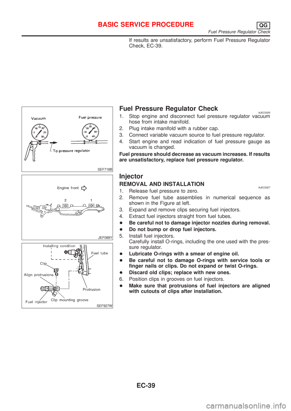
2001 NISSAN ALMERA N16 Fuel gauge
[x] Cancel search: Fuel gaugePage 58 of 2493

NJMA0036
Shown below are Pre-delivery Inspection Items required for the new vehicle. It is recommended that
necessary items other than those listed here be added, paying due regard to the conditions in each
country.
Perform applicable items on each model. Consult text of this section for specifications.
UNDER HOOD Ð engine off
Radiator coolant level and coolant hose connections for leaks
Battery fluid level, specific gravity and conditions of battery terminals
Drive belts tension
Fuel filter for water or dusts (Diesel only), and fuel lines and connections for leaks
Engine oil level and oil leaks
Clutch and brake reservoir fluid level and fluid lines for leaks
Windshield and rear window washer and headlamp cleaner reservoir fluid level
Power steering reservoir fluid level and hose connections for leaks
ON INSIDE AND OUTSIDE
Remove front spring/strut spacer (If applicable)
Operation of all instruments, gauges, lights and accessories
Operation of horn(s), wiper and washer
Steering lock for operation
Check air conditioner for gas leaks
Front and rear seats, and seat belts for operation
All moldings, trims and fittings for fit and alignment
All windows for operation and alignment
Hood, trunk lid, door panels for fit and alignment
Latches, keys and locks for operation
Weatherstrips for adhesion and fit
Headlamp aiming
Tighten wheel nuts (Inc. inner nuts if applicable)
Tire pressure (Inc. spare tire)
Check front wheels for toe-in
Install clock/voltmeter/room lamp fuse (If applicable)
Install deodorizing filter to air conditioner (If applicable)
Remove wiper blade protectors (If applicable)
UNDER BODY
Manual transmission/transaxle, transfer and differential gear oil level
Brake and fuel lines and oil/fluid reservoirs for leaks
Tighten bolts and nuts of steering linkage and gear box, suspension, propeller shafts and drive shafts
Tighten rear body bolts and nuts (Models with wooden bed only)
ROAD TEST
Clutch operation
Parking brake operation
Service brake operation
Automatic transmission/transaxle shift timing and kickdown
Steering control and returnability
Engine performance
Squeaks and rattles
ENGINE OPERATING AND HOT
Adjust idle speed
Automatic transmission/transaxle fluid level
Engine idling and stop knob operation (Diesel only)
FINAL INSPECTION
Install necessary parts (outside mirror, wheel covers, seat belts, mat, carpet or mud flaps)
Inspect for interior and exterior metal and paint damage
Check for spare tire, jack, tools (wheel chock), and literature
Wash, clean interior and exterior
: Not applicable to this model
PRE-DELIVERY INSPECTION ITEMS
MA-2
Page 59 of 2493

NJMA0004
General maintenance includes those items which should be checked during the normal day-to-day operation
of the vehicle. They are essential if the vehicle is to continue operating properly. The owners can perform the
checks and inspections themselves or they can have their NISSAN dealers do them for a nominal charge.
OUTSIDE THE VEHICLE
The maintenance items listed here should be performed from time to time, unless otherwise specified.
Item Reference page
TiresCheck the pressure with a gauge periodically when at a service station,
including the spare, and adjust to the specified pressure if necessary. Check
carefully for damage, cuts or excessive wear.Ð
Windshield wiper
bladesCheck for cracks or wear if not functioning correctly. Ð
Doors and engine
hoodCheck that all doors, the engine hood, the trunk lid and back door operate
properly. Also ensure that all latches lock securely. Lubricate if necessary.
Make sure that the secondary latch keeps the hood from opening when the
primary latch is released.
When driving in areas using road salt or other corrosive materials, check for
lubrication frequently.BT-7
BT-16
Tire rotationTires should be rotated every 10,000 km (6,000 miles). SU-7
INSIDE THE VEHICLE
The maintenance items listed here should be checked on a regular basis, such as when performing periodic maintenance, cleaning the
vehicle, etc.
Item Reference page
LampsMake sure that the headlamps, stop lamps, tail lamps, turn signal lamps,
and other lamps are all operating properly and installed securely. Also check
headlamp aim.Ð
Warning lamps and
chimesMake sure that all warning lamps and buzzers/chimes are operating prop-
erly.Ð
Steering wheelCheck that it has the specified play.
Check for changes in the steering conditions, such as excessive free play,
hard steering or strange noises.
Free play: Less than 35 mm (1.38 in)Ð
Seat beltsCheck that all parts of the seat belt system (e.g. buckles, anchors, adjusters
and retractors) operate properly and smoothly, and are installed securely.
Check the belt webbing for cuts, fraying, wear or damage.RS-4
UNDER THE HOOD AND VEHICLE
The maintenance items listed here should be checked periodically e.g. each time you check the engine oil or refuel.
Item Reference page
Windshield washer
fluidCheck that there is adequate fluid in the tank. Ð
Engine coolant levelCheck the coolant level when the engine is cold. LC-18, LC-43
Engine oil levelCheck the level after parking the vehicle (on level ground) and turning off
the engine.LC-8, LC-30
Brake and clutch
fluid levelsMake sure that the brake and clutch fluid levels are between the ªMAXº and
ªMINº lines on the reservoir.BR-7
BatteryCheck the fluid level in each cell. It should be between the ªMAXº and ªMINº
lines.Ð
GENERAL MAINTENANCE
MA-3
Page 92 of 2493

NJEM0007
1. Warm up engine.
2. Turn ignition switch OFF.
3. Release fuel pressure.
Refer to EC-38, ªReleasing Fuel Pressureº.
4. Remove ignition coils.
5. Remove spark plugs.
+Clean area around plug with compressed air before removing
the spark plug.
SEM973E
AEM308
6. Attach a compression tester to No. 1 cylinder.
7. Depress accelerator pedal fully to keep throttle valve wide
open.
8. Crank engine and record highest gauge indication.
9. Repeat the measurement on each cylinder as shown above.
+Always use a fully-charged battery to obtain specified
engine speed.
Compression pressure: kPa (bar, kg/cm
2, psi)/rpm
QG18DE
Standard
1,324 (13.24, 13.5, 192)/350
Minimum
1,128 (11.28, 11.5, 164)/350
Maximum allowable difference between cylinders
98 (0.98, 1.0, 14)/350
QG15DE
Standard
1,372 (13.720, 13.99, 198.9)/350
Minimum
1,176 (11.759, 11.99, 170.5)/350
Maximum allowable difference between cylinders
98 (0.98, 1.0, 14)/350
10. If cylinder compression in one or more cylinders is low, pour a
small amount of engine oil into the cylinder through the spark
plug hole and retest compression.
+If adding oil improves cylinder compression, piston rings
may be worn or damaged. If so, replace piston rings after
checking piston.
+If pressure stays low, a valve may be sticking or seating
improperly. Inspect and repair valve and valve seat. Refer
to SDS, EM-70. If valve or valve seat is damaged
excessively, replace them.
+If compression in any two adjacent cylinders is low and if add-
ing oil does not improve compression, there is leakage past the
gasket surface. If so, replace cylinder head gasket.
11. Reinstall spark plugs, ignition coils and fuel pump fuse.
12. Perform ªSelf-diagnosis Procedureº referring to EC-68, ªHow
to Erase DTCº if any DTC appears.
MEASUREMENT OF COMPRESSION PRESSUREQG
EM-14
Page 160 of 2493

NJEM0053
JEM111G
1. Warm up engine.
2. Turn ignition switch OFF.
3. Using CONSULT-II, make sure no error codes are indicated for
self-diagnosis items. Refer to EC-492, ªTrouble Diagnosis Ð
INDEXº.
+Do not disconnect CONSULT-II until the end of this operation;
it will be used to check engine rpm and for error detection at
the end of this operation.
4. Disconnect the negative battery terminal.
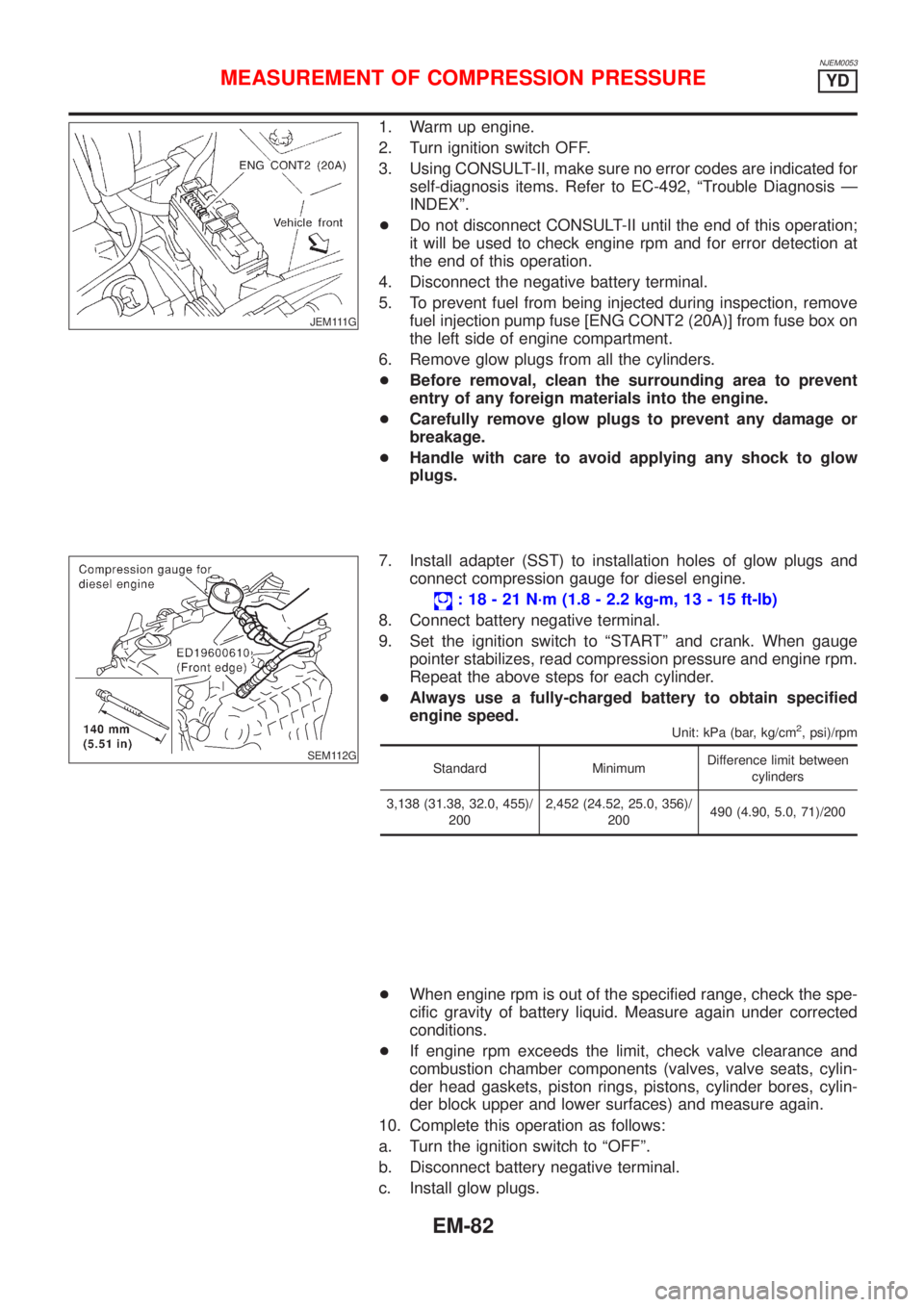
5. To prevent fuel from being injected during inspection, remove
fuel injection pump fuse [ENG CONT2 (20A)] from fuse box on
the left side of engine compartment.
6. Remove glow plugs from all the cylinders.
+Before removal, clean the surrounding area to prevent
entry of any foreign materials into the engine.
+Carefully remove glow plugs to prevent any damage or
breakage.
+Handle with care to avoid applying any shock to glow
plugs.
SEM112G
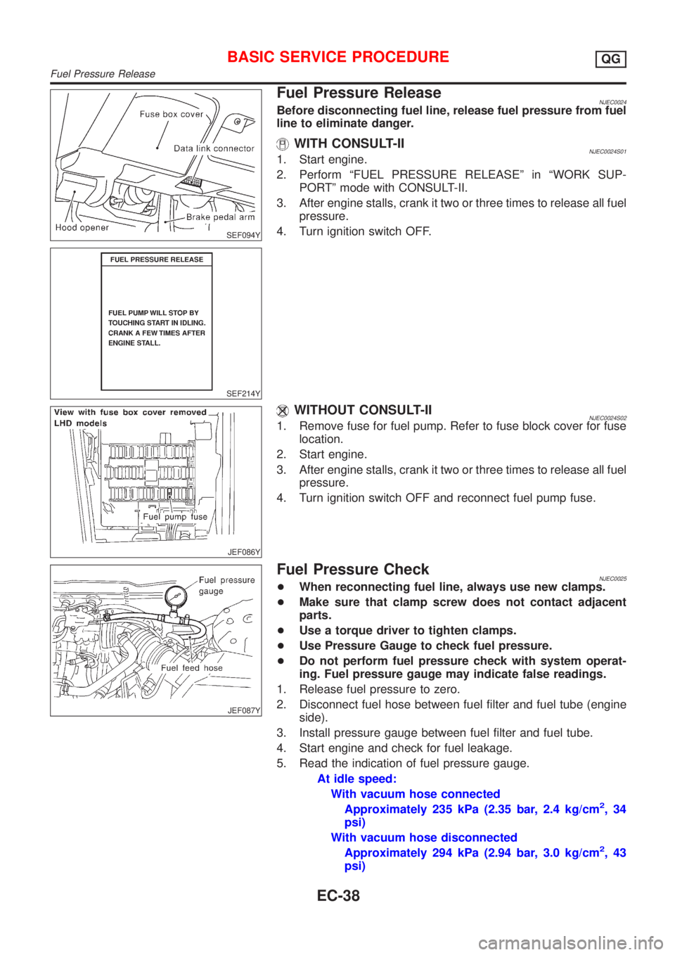
7. Install adapter (SST) to installation holes of glow plugs and
connect compression gauge for diesel engine.
: 18 - 21 N´m (1.8 - 2.2 kg-m, 13 - 15 ft-lb)
8. Connect battery negative terminal.
9. Set the ignition switch to ªSTARTº and crank. When gauge
pointer stabilizes, read compression pressure and engine rpm.
Repeat the above steps for each cylinder.
+Always use a fully-charged battery to obtain specified
engine speed.
Unit: kPa (bar, kg/cm2, psi)/rpm
Standard MinimumDifference limit between
cylinders
3,138 (31.38, 32.0, 455)/
2002,452 (24.52, 25.0, 356)/
200490 (4.90, 5.0, 71)/200
+When engine rpm is out of the specified range, check the spe-
cific gravity of battery liquid. Measure again under corrected
conditions.
+If engine rpm exceeds the limit, check valve clearance and
combustion chamber components (valves, valve seats, cylin-
der head gaskets, piston rings, pistons, cylinder bores, cylin-
der block upper and lower surfaces) and measure again.
10. Complete this operation as follows:
a. Turn the ignition switch to ªOFFº.
b. Disconnect battery negative terminal.
c. Install glow plugs.
MEASUREMENT OF COMPRESSION PRESSUREYD
EM-82
Page 334 of 2493

SEF094Y
SEF214Y
Fuel Pressure ReleaseNJEC0024Before disconnecting fuel line, release fuel pressure from fuel
line to eliminate danger.
WITH CONSULT-IINJEC0024S011. Start engine.
2. Perform ªFUEL PRESSURE RELEASEº in ªWORK SUP-
PORTº mode with CONSULT-II.
3. After engine stalls, crank it two or three times to release all fuel
pressure.
4. Turn ignition switch OFF.
JEF086Y
WITHOUT CONSULT-IINJEC0024S021. Remove fuse for fuel pump. Refer to fuse block cover for fuse
location.
2. Start engine.
3. After engine stalls, crank it two or three times to release all fuel
pressure.
4. Turn ignition switch OFF and reconnect fuel pump fuse.
JEF087Y
Fuel Pressure CheckNJEC0025+When reconnecting fuel line, always use new clamps.
+Make sure that clamp screw does not contact adjacent
parts.
+Use a torque driver to tighten clamps.
+Use Pressure Gauge to check fuel pressure.
+Do not perform fuel pressure check with system operat-
ing. Fuel pressure gauge may indicate false readings.
1. Release fuel pressure to zero.
2. Disconnect fuel hose between fuel filter and fuel tube (engine
side).
3. Install pressure gauge between fuel filter and fuel tube.
4. Start engine and check for fuel leakage.
5. Read the indication of fuel pressure gauge.
At idle speed:
With vacuum hose connected
Approximately 235 kPa (2.35 bar, 2.4 kg/cm
2,34
psi)
With vacuum hose disconnected
Approximately 294 kPa (2.94 bar, 3.0 kg/cm
2,43
psi)
BASIC SERVICE PROCEDUREQG
Fuel Pressure Release
EC-38
Page 335 of 2493

If results are unsatisfactory, perform Fuel Pressure Regulator
Check, EC-39.
SEF718B
Fuel Pressure Regulator CheckNJEC00261. Stop engine and disconnect fuel pressure regulator vacuum
hose from intake manifold.
2. Plug intake manifold with a rubber cap.
3. Connect variable vacuum source to fuel pressure regulator.
4. Start engine and read indication of fuel pressure gauge as
vacuum is changed.
Fuel pressure should decrease as vacuum increases. If results
are unsatisfactory, replace fuel pressure regulator.
JEF088Y
SEF927W
Injector
REMOVAL AND INSTALLATIONNJEC00271. Release fuel pressure to zero.
2. Remove fuel tube assemblies in numerical sequence as
shown in the Figure at left.
3. Expand and remove clips securing fuel injectors.
4. Extract fuel injectors straight from fuel tubes.
+Be careful not to damage injector nozzles during removal.
+Do not bump or drop fuel injectors.
5. Install fuel injectors.
Carefully install O-rings, including the one used with the pres-
sure regulator.
+Lubricate O-rings with a smear of engine oil.
+Be careful not to damage O-rings with service tools or
finger nails or clips. Do not expand or twist O-rings.
+Discard old clips; replace with new ones.
6. Position clips in grooves on fuel injectors.
+Make sure that protrusions of fuel injectors are aligned
with cutouts of clips after installation.
BASIC SERVICE PROCEDUREQG
Fuel Pressure Regulator Check
EC-39
Page 372 of 2493

MI Fuel mixture condition in the exhaust gas Air fuel ratio feedback control condition
ON Lean
Closed loop system
OFF Rich
*Remains ON or OFF Any condition Open loop system
*: Maintains conditions just before switching to open loop.
To check the heated oxygen sensor 1 (front) function, start engine in the Diagnostic Test Mode II and warm
it up until engine coolant temperature indicator points to the middle of the gauge.
Next run engine at about 2,000 rpm for about 2 minutes under no-load conditions. Then make sure that the
MI comes ON more than 5 times within 10 seconds with engine running at 2,000 rpm under no-load.
OBD System Operation Chart (With Euro-OBD
Models Only)
NJEC0033RELATIONSHIP BETWEEN MI, 1ST TRIP DTC, DTC, AND DETECTABLE ITEMSNJEC0033S01+When a malfunction is detected for the first time, the 1st trip DTC and the 1st trip freeze frame data are
stored in the ECM memory.
+When the same malfunction is detected in two consecutive trips, the DTC and the freeze frame data are
stored in the ECM memory, and the MI will come on. For details, refer to ªTwo Trip Detection Logicº on
EC-57.
+The MI will go off after the vehicle is driven 3 times with no malfunction. The drive is counted only when
the recorded driving pattern is met (as stored in the ECM). If another malfunction occurs while counting,
the counter will reset.
+The DTC and the freeze frame data will be stored until the vehicle is driven 40 times (driving pattern A)
without the same malfunction recurring (except for Misfire and Fuel Injection System). For Misfire and Fuel
Injection System, the DTC and freeze frame data will be stored until the vehicle is driven 80 times (driv-
ing pattern C) without the same malfunction recurring. The ªTIMEº in ªSELF-DIAGNOSTIC RESULTSº
mode of CONSULT-II will count the number of times the vehicle is driven.
+The 1st trip DTC is not displayed when the self-diagnosis results in ªOKº for the 2nd trip.
SUMMARY CHARTNJEC0033S02
Items Fuel Injection System Misfire Other
MI (goes off) 3 (pattern B) 3 (pattern B) 3 (pattern B)
DTC, Freeze Frame Data (no display) 80 (pattern C) 80 (pattern C) 40 (pattern A)
1st Trip DTC (clear) 1 (pattern C), *1 1 (pattern C), *1 1 (pattern B)
1st Trip Freeze Frame Data (clear) *1, *2 *1, *2 1 (pattern B)
For details about patterns ªBº and ªCº under ªFuel Injection Systemº and ªMisfireº, see EC-78.
For details about patterns ªAº and ªBº under ªOtherº, see EC-80.
*1: Clear timing is at the moment OK is detected.
*2: Clear timing is when the same malfunction is detected in the 2nd trip.
ON BOARD DIAGNOSTIC SYSTEM DESCRIPTIONQG
Malfunction Indicator (MI) (Cont'd)
EC-76
Page 548 of 2493

4 CHECK FUEL PRESSURE
1. Release fuel pressure to zero.
Refer to EC-38.
2. Install fuel pressure gauge and check fuel pressure.
At idling:
When fuel pressure regulator valve vacuum hose is connected.
235 kPa (2.35 bar, 2.4 kg/cm
2, 34 psi)
When fuel pressure regulator valve vacuum hose is disconnected.
294 kPa (2.94 bar, 3.0 kg/cm
2, 43 psi)
OK or NG
OK©GO TO 6.
NG©GO TO 5.
5 DETECT MALFUNCTIONING PART
Check the following.
+Fuel pump and circuit (Refer to EC-464.)
+Fuel pressure regulator (Refer to EC-39.)
+Fuel lines (Refer to ªENGINE MAINTENANCEº in MA section.)
+Fuel filter for clogging
©Repair or replace.
6 CHECK MASS AIR FLOW SENSOR
With CONSULT-II
Check ªMASS AIR FLOWº in ªDATA MONITORº mode with CONSULT-II.
at idling: 1.0 - 4.0 g´m/sec
at 2,500 rpm: 5.0 - 10.0 g´m/sec
With GST
Check mass air flow sensor signal in MODE 1 with GST.
at idling: 1.0 - 4.0 g´m/sec
at 2,500 rpm: 5.0 - 10.0 g´m/sec
OK or NG
OK©GO TO 7.
NG©Check connectors for rusted terminals or loose connections in the mass air flow sensor
circuit or engine grounds. Refer to EC-152.
DTC P0171 FUEL INJECTION SYSTEM FUNCTION (LEAN SIDE)QG
Diagnostic Procedure (Cont'd)
EC-252