2001 NISSAN ALMERA N16 Fuel gauge
[x] Cancel search: Fuel gaugePage 2210 of 2493
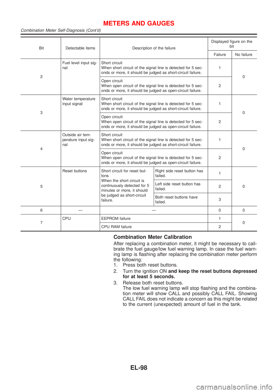
Bit Detectable items Description of the failureDisplayed figure on the
bit
Failure No failure
2Fuel level input sig-
nalShort circuit
When short circuit of the signal line is detected for 5 sec-
onds or more, it should be judged as short-circuit failure.1
0
Open circuit
When open circuit of the signal line is detected for 5 sec-
onds or more, it should be judged as open-circuit failure.2
3Water temperature
input signalShort circuit
When short circuit of the signal line is detected for 5 sec-
onds or more, it should be judged as short-circuit failure.1
0
Open circuit
When open circuit of the signal line is detected for 5 sec-
onds or more, it should be judged as open-circuit failure.2
4Outside air tem-
perature input sig-
nalShort circuit
When short circuit of the signal line is detected for 5 sec-
onds or more, it should be judged as short-circuit failure.1
0
Open circuit
When open circuit of the signal line is detected for 5 sec-
onds or more, it should be judged as open-circuit failure.2
5Reset buttons Short circuit for reset but-
tons
When the short circuit is
continuously detected for 5
minutes or more, it should
be judged as short-circuit
failure.Right side reset button has
failed.1
0 Left side reset button has
failed.2
Both reset buttons have
failed.3
6Ð Ð 00
7CPU EEPROM failure 1
0
CPU RAM failure 2
Combination Meter Calibration
After replacing a combination meter, it might be necessary to cali-
brate the fuel gauge/low fuel warning lamp. In case the fuel warn-
ing lamp is flashing after replacing the combination meter perform
the following:
1. Press both reset buttons.
2. Turn the ignition ONand keep the reset buttons depressed
for at least 5 seconds.
3. Release both reset buttons.
The low fuel warning lamp will stop flashing and the combina-
tion meter will show CALL and possibly CALL FAIL. Showing
CALL FAIL does not indicate a concern as this might be related
to the current (unexpected) amount of fuel in the tank.
METERS AND GAUGES
Combination Meter Self-Diagnosis (Cont'd)
EL-98
Page 2212 of 2493
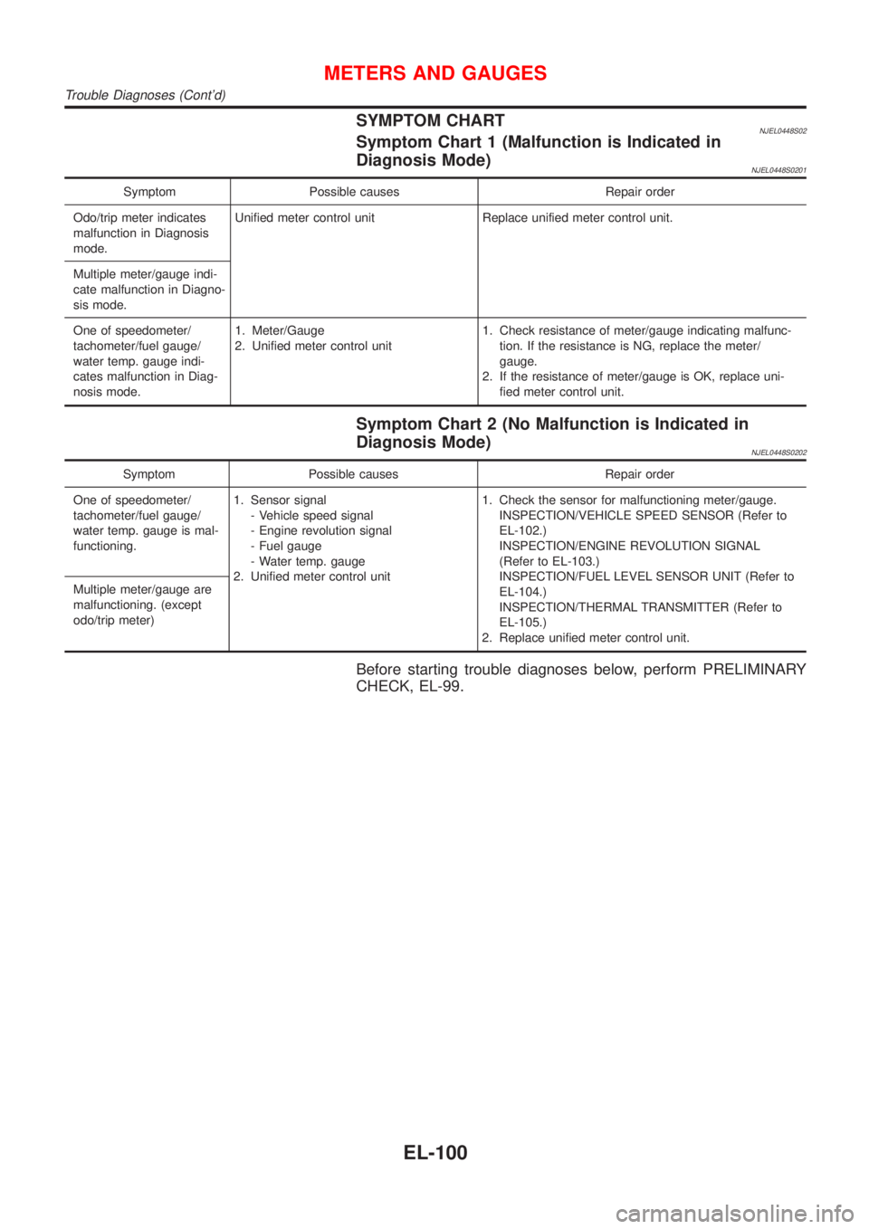
SYMPTOM CHARTNJEL0448S02Symptom Chart 1 (Malfunction is Indicated in
Diagnosis Mode)
NJEL0448S0201
Symptom Possible causes Repair order
Odo/trip meter indicates
malfunction in Diagnosis
mode.Unified meter control unit Replace unified meter control unit.
Multiple meter/gauge indi-
cate malfunction in Diagno-
sis mode.
One of speedometer/
tachometer/fuel gauge/
water temp. gauge indi-
cates malfunction in Diag-
nosis mode.1. Meter/Gauge
2. Unified meter control unit1. Check resistance of meter/gauge indicating malfunc-
tion. If the resistance is NG, replace the meter/
gauge.
2. If the resistance of meter/gauge is OK, replace uni-
fied meter control unit.
Symptom Chart 2 (No Malfunction is Indicated in
Diagnosis Mode)
NJEL0448S0202
Symptom Possible causes Repair order
One of speedometer/
tachometer/fuel gauge/
water temp. gauge is mal-
functioning.1. Sensor signal
- Vehicle speed signal
- Engine revolution signal
- Fuel gauge
- Water temp. gauge
2. Unified meter control unit1. Check the sensor for malfunctioning meter/gauge.
INSPECTION/VEHICLE SPEED SENSOR (Refer to
EL-102.)
INSPECTION/ENGINE REVOLUTION SIGNAL
(Refer to EL-103.)
INSPECTION/FUEL LEVEL SENSOR UNIT (Refer to
EL-104.)
INSPECTION/THERMAL TRANSMITTER (Refer to
EL-105.)
2. Replace unified meter control unit. Multiple meter/gauge are
malfunctioning. (except
odo/trip meter)
Before starting trouble diagnoses below, perform PRELIMINARY
CHECK, EL-99.
METERS AND GAUGES
Trouble Diagnoses (Cont'd)
EL-100
Page 2216 of 2493
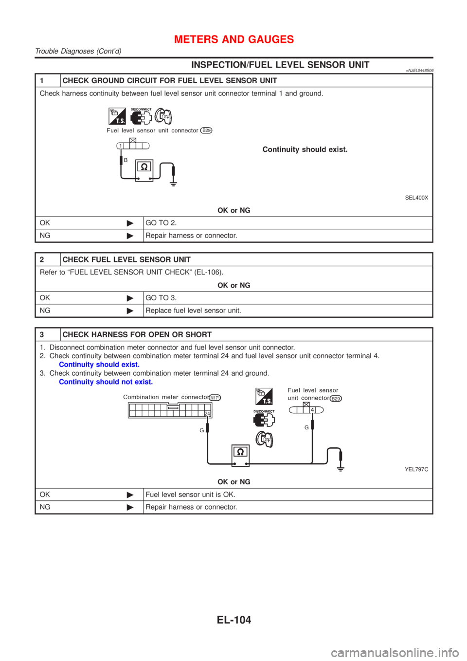
INSPECTION/FUEL LEVEL SENSOR UNIT=NJEL0448S06
1 CHECK GROUND CIRCUIT FOR FUEL LEVEL SENSOR UNIT
Check harness continuity between fuel level sensor unit connector terminal 1 and ground.
SEL400X
OK or NG
OK©GO TO 2.
NG©Repair harness or connector.
2 CHECK FUEL LEVEL SENSOR UNIT
Refer to ªFUEL LEVEL SENSOR UNIT CHECKº (EL-106).
OK or NG
OK©GO TO 3.
NG©Replace fuel level sensor unit.
3 CHECK HARNESS FOR OPEN OR SHORT
1. Disconnect combination meter connector and fuel level sensor unit connector.
2. Check continuity between combination meter terminal 24 and fuel level sensor unit connector terminal 4.
Continuity should exist.
3. Check continuity between combination meter terminal 24 and ground.
Continuity should not exist.
YEL797C
OK or NG
OK©Fuel level sensor unit is OK.
NG©Repair harness or connector.
METERS AND GAUGES
Trouble Diagnoses (Cont'd)
EL-104
Page 2218 of 2493
SEL498X
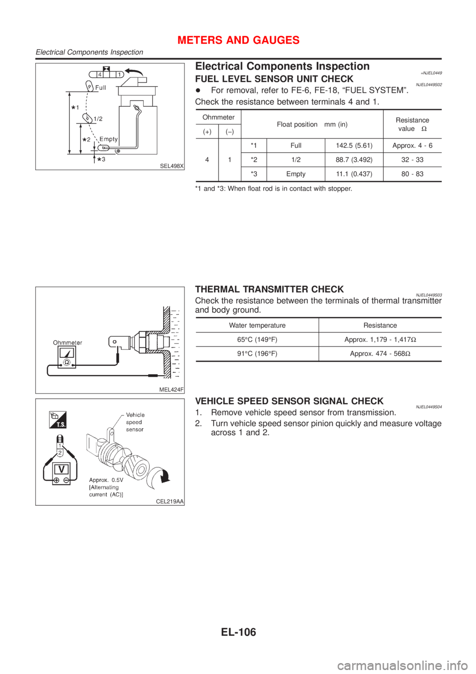
Electrical Components Inspection=NJEL0449FUEL LEVEL SENSOR UNIT CHECKNJEL0449S02+For removal, refer to FE-6, FE-18, ªFUEL SYSTEMº.
Check the resistance between terminals 4 and 1.
Ohmmeter
Float position mm (in)Resistance
valueW
(+) (þ)
41*1 Full 142.5 (5.61) Approx.4-6
*2 1/2 88.7 (3.492) 32 - 33
*3 Empty 11.1 (0.437) 80 - 83
*1 and *3: When float rod is in contact with stopper.
MEL424F
THERMAL TRANSMITTER CHECKNJEL0449S03Check the resistance between the terminals of thermal transmitter
and body ground.
Water temperature Resistance
65ÉC (149ÉF) Approx. 1,179 - 1,417W
91ÉC (196ÉF) Approx. 474 - 568W
CEL219AA
VEHICLE SPEED SENSOR SIGNAL CHECKNJEL0449S041. Remove vehicle speed sensor from transmission.
2. Turn vehicle speed sensor pinion quickly and measure voltage
across 1 and 2.
METERS AND GAUGES
Electrical Components Inspection
EL-106
Page 2479 of 2493
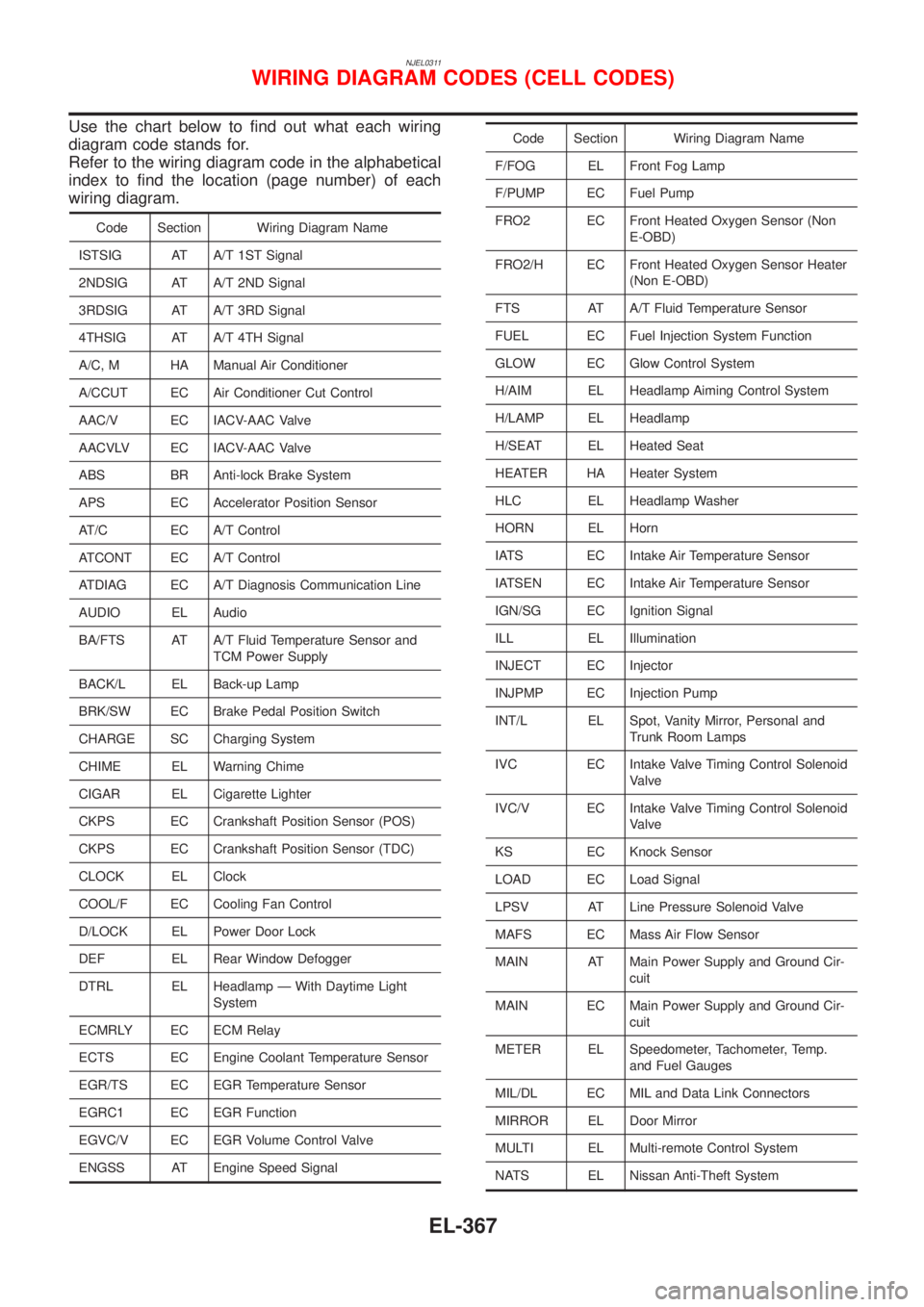
NJEL0311
Use the chart below to find out what each wiring
diagram code stands for.
Refer to the wiring diagram code in the alphabetical
index to find the location (page number) of each
wiring diagram.
Code Section Wiring Diagram Name
ISTSIG AT A/T 1ST Signal
2NDSIG AT A/T 2ND Signal
3RDSIG AT A/T 3RD Signal
4THSIG AT A/T 4TH Signal
A/C, M HA Manual Air Conditioner
A/CCUT EC Air Conditioner Cut Control
AAC/V EC IACV-AAC Valve
AACVLV EC IACV-AAC Valve
ABS BR Anti-lock Brake System
APS EC Accelerator Position Sensor
AT/C EC A/T Control
ATCONT EC A/T Control
ATDIAG EC A/T Diagnosis Communication Line
AUDIO EL Audio
BA/FTS AT A/T Fluid Temperature Sensor and
TCM Power Supply
BACK/L EL Back-up Lamp
BRK/SW EC Brake Pedal Position Switch
CHARGE SC Charging System
CHIME EL Warning Chime
CIGAR EL Cigarette Lighter
CKPS EC Crankshaft Position Sensor (POS)
CKPS EC Crankshaft Position Sensor (TDC)
CLOCK EL Clock
COOL/F EC Cooling Fan Control
D/LOCK EL Power Door Lock
DEF EL Rear Window Defogger
DTRL EL Headlamp Ð With Daytime Light
System
ECMRLY EC ECM Relay
ECTS EC Engine Coolant Temperature Sensor
EGR/TS EC EGR Temperature Sensor
EGRC1 EC EGR Function
EGVC/V EC EGR Volume Control Valve
ENGSS AT Engine Speed Signal
Code Section Wiring Diagram Name
F/FOG EL Front Fog Lamp
F/PUMP EC Fuel Pump
FRO2 EC Front Heated Oxygen Sensor (Non
E-OBD)
FRO2/H EC Front Heated Oxygen Sensor Heater
(Non E-OBD)
FTS AT A/T Fluid Temperature Sensor
FUEL EC Fuel Injection System Function
GLOW EC Glow Control System
H/AIM EL Headlamp Aiming Control System
H/LAMP EL Headlamp
H/SEAT EL Heated Seat
HEATER HA Heater System
HLC EL Headlamp Washer
HORN EL Horn
IATS EC Intake Air Temperature Sensor
IATSEN EC Intake Air Temperature Sensor
IGN/SG EC Ignition Signal
ILL EL Illumination
INJECT EC Injector
INJPMP EC Injection Pump
INT/L EL Spot, Vanity Mirror, Personal and
Trunk Room Lamps
IVC EC Intake Valve Timing Control Solenoid
Valve
IVC/V EC Intake Valve Timing Control Solenoid
Valve
KS EC Knock Sensor
LOAD EC Load Signal
LPSV AT Line Pressure Solenoid Valve
MAFS EC Mass Air Flow Sensor
MAIN AT Main Power Supply and Ground Cir-
cuit
MAIN EC Main Power Supply and Ground Cir-
cuit
METER EL Speedometer, Tachometer, Temp.
and Fuel Gauges
MIL/DL EC MIL and Data Link Connectors
MIRROR EL Door Mirror
MULTI EL Multi-remote Control System
NATS EL Nissan Anti-Theft System
WIRING DIAGRAM CODES (CELL CODES)
EL-367
Page 2484 of 2493
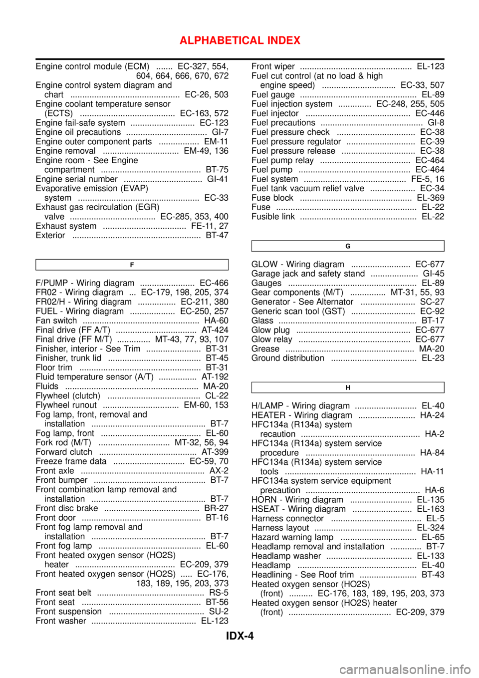
Engine control module (ECM) ....... EC-327, 554,
604, 664, 666, 670, 672
Engine control system diagram and
chart .............................................. EC-26, 503
Engine coolant temperature sensor
(ECTS) ........................................ EC-163, 572
Engine fail-safe system ........................... EC-123
Engine oil precautions .................................. GI-7
Engine outer component parts ................. EM-11
Engine removal ................................ EM-49, 136
Engine room - See Engine
compartment .......................................... BT-75
Engine serial number ................................. GI-41
Evaporative emission (EVAP)
system ................................................... EC-33
Exhaust gas recirculation (EGR)
valve .................................... EC-285, 353, 400
Exhaust system ................................... FE-11, 27
Exterior ...................................................... BT-47
F
F/PUMP - Wiring diagram ....................... EC-466
FR02 - Wiring diagram ... EC-179, 198, 205, 374
FR02/H - Wiring diagram ................ EC-211, 380
FUEL - Wiring diagram ................... EC-250, 257
Fan switch ................................................. HA-60
Final drive (FF A/T) .................................. AT-424
Final drive (FF M/T) .............. MT-43, 77, 93, 107
Finisher, interior - See Trim ....................... BT-31
Finisher, trunk lid ....................................... BT-45
Floor trim ................................................... BT-31
Fluid temperature sensor (A/T) ................ AT-192
Fluids ........................................................ MA-20
Flywheel (clutch) ....................................... CL-22
Flywheel runout ................................ EM-60, 153
Fog lamp, front, removal and
installation ................................................ BT-7
Fog lamp, front .......................................... EL-60
Fork rod (M/T) .............................. MT-32, 56, 94
Forward clutch ......................................... AT-399
Freeze frame data .............................. EC-59, 70
Front axle .................................................... AX-2
Front bumper ............................................... BT-7
Front combination lamp removal and
installation ................................................ BT-7
Front disc brake ........................................ BR-27
Front door .................................................. BT-16
Front fog lamp removal and
installation ................................................ BT-7
Front fog lamp ........................................... EL-60
Front heated oxygen sensor (HO2S)
heater .......................................... EC-209, 379
Front heated oxygen sensor (HO2S) ..... EC-176,
183, 189, 195, 203, 373
Front seat belt ............................................. RS-5
Front seat .................................................. BT-56
Front suspension ........................................ SU-2
Front washer ............................................ EL-123Front wiper ............................................... EL-123
Fuel cut control (at no load & high
engine speed) ............................... EC-33, 507
Fuel gauge ................................................. EL-89
Fuel injection system .............. EC-248, 255, 505
Fuel injector ............................................ EC-446
Fuel precautions ........................................... GI-8
Fuel pressure check ................................. EC-38
Fuel pressure regulator ............................. EC-39
Fuel pressure release ............................... EC-38
Fuel pump relay ...................................... EC-464
Fuel pump ............................................... EC-464
Fuel system ........................................... FE-5, 16
Fuel tank vacuum relief valve ................... EC-34
Fuse block ............................................... EL-369
Fuse ........................................................... EL-22
Fusible link ................................................. EL-22
G
GLOW - Wiring diagram ......................... EC-677
Garage jack and safety stand .................... GI-45
Gauges ...................................................... EL-89
Gear components (M/T) ............... MT-31, 55, 93
Generator - See Alternator ....................... SC-27
Generic scan tool (GST) ........................... EC-92
Glass .......................................................... BT-17
Glow plug ................................................ EC-677
Glow relay ............................................... EC-677
Grease ...................................................... MA-20
Ground distribution .................................... EL-23
H
H/LAMP - Wiring diagram .......................... EL-40
HEATER - Wiring diagram ........................ HA-24
HFC134a (R134a) system
recaution .................................................. HA-2
HFC134a (R134a) system service
procedure .............................................. HA-84
HFC134a (R134a) system service
tools ....................................................... HA-11
HFC134a system service equipment
precaution ................................................ HA-6
HORN - Wiring diagram .......................... EL-135
HSEAT - Wiring diagram ......................... EL-163
Harness connector ...................................... EL-5
Harness layout ......................................... EL-324
Hazard warning lamp ................................ EL-65
Headlamp removal and installation ............. BT-7
Headlamp washer .................................... EL-133
Headlamp .................................................. EL-40
Headlining - See Roof trim ........................ BT-43
Heated oxygen sensor (HO2S)
(front) .......... EC-176, 183, 189, 195, 203, 373
Heated oxygen sensor (HO2S) heater
(front) ........................................... EC-209, 379
ALPHABETICAL INDEX
IDX-4