Page 1290 of 2493
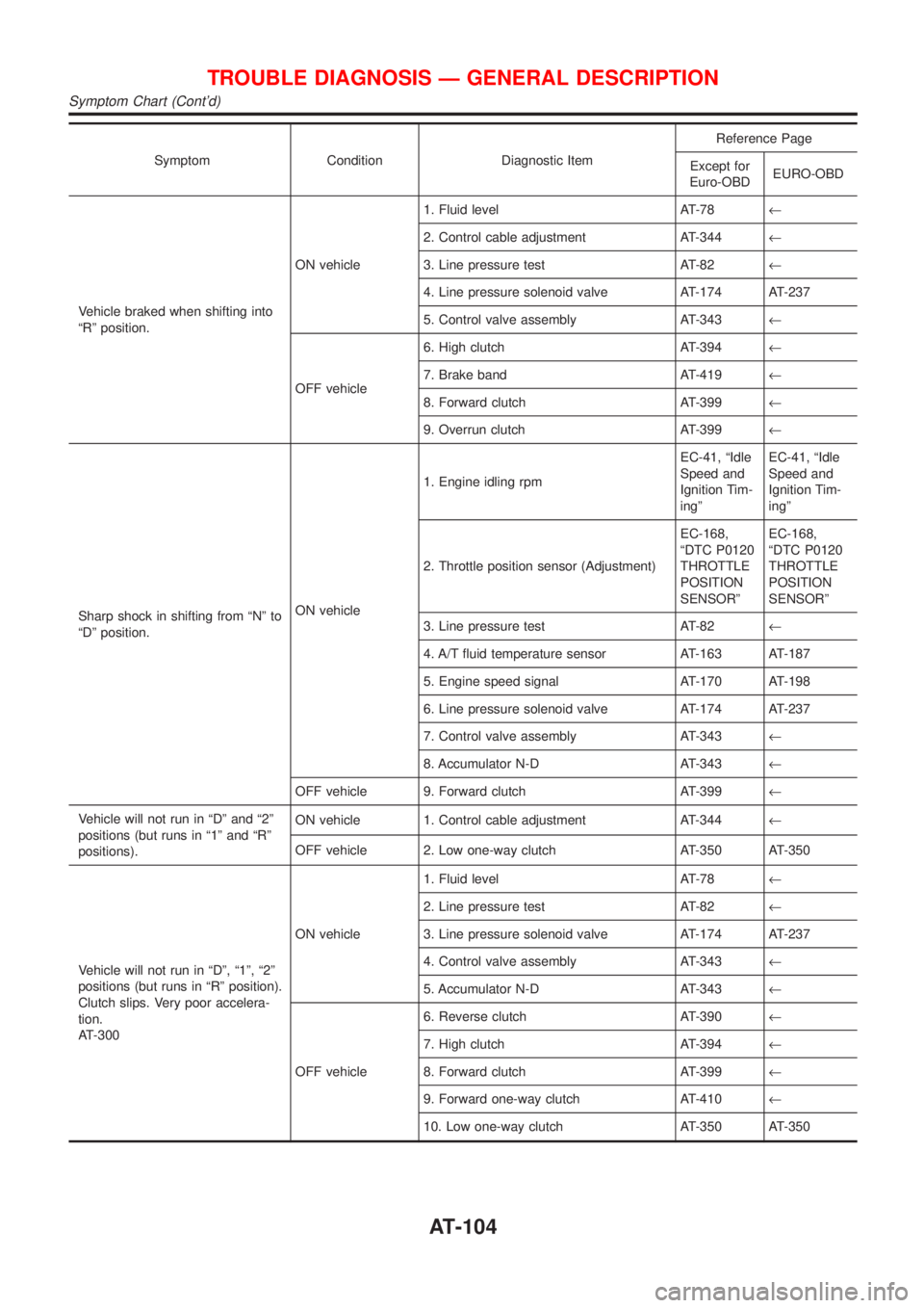
Symptom Condition Diagnostic ItemReference Page
Except for
Euro-OBDEURO-OBD
Vehicle braked when shifting into
ªRº position.ON vehicle1. Fluid level AT-78¬
2. Control cable adjustment AT-344¬
3. Line pressure test AT-82¬
4. Line pressure solenoid valve AT-174 AT-237
5. Control valve assembly AT-343¬
OFF vehicle6. High clutch AT-394¬
7. Brake band AT-419¬
8. Forward clutch AT-399¬
9. Overrun clutch AT-399¬
Sharp shock in shifting from ªNº to
ªDº position.ON vehicle1. Engine idling rpmEC-41, ªIdle
Speed and
Ignition Tim-
ingºEC-41, ªIdle
Speed and
Ignition Tim-
ingº
2. Throttle position sensor (Adjustment)EC-168,
ªDTC P0120
THROTTLE
POSITION
SENSORºEC-168,
ªDTC P0120
THROTTLE
POSITION
SENSORº
3. Line pressure test AT-82¬
4. A/T fluid temperature sensor AT-163 AT-187
5. Engine speed signal AT-170 AT-198
6. Line pressure solenoid valve AT-174 AT-237
7. Control valve assembly AT-343¬
8. Accumulator N-D AT-343¬
OFF vehicle 9. Forward clutch AT-399¬
Vehicle will not run in ªDº and ª2º
positions (but runs in ª1º and ªRº
positions).ON vehicle 1. Control cable adjustment AT-344¬
OFF vehicle 2. Low one-way clutch AT-350 AT-350
Vehicle will not run in ªDº, ª1º, ª2º
positions (but runs in ªRº position).
Clutch slips. Very poor accelera-
tion.
AT-300ON vehicle1. Fluid level AT-78¬
2. Line pressure test AT-82¬
3. Line pressure solenoid valve AT-174 AT-237
4. Control valve assembly AT-343¬
5. Accumulator N-D AT-343¬
OFF vehicle6. Reverse clutch AT-390¬
7. High clutch AT-394¬
8. Forward clutch AT-399¬
9. Forward one-way clutch AT-410¬
10. Low one-way clutch AT-350 AT-350
TROUBLE DIAGNOSIS Ð GENERAL DESCRIPTION
Symptom Chart (Cont'd)
AT-104
Page 1293 of 2493
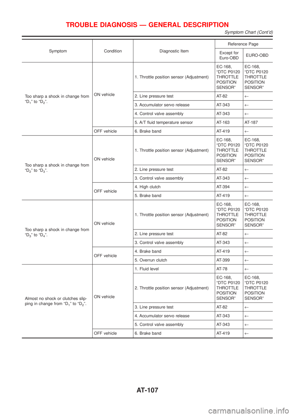
Symptom Condition Diagnostic ItemReference Page
Except for
Euro-OBDEURO-OBD
Too sharp a shock in change from
ªD
1ºtoªD2º.ON vehicle1. Throttle position sensor (Adjustment)EC-168,
ªDTC P0120
THROTTLE
POSITION
SENSORºEC-168,
ªDTC P0120
THROTTLE
POSITION
SENSORº
2. Line pressure test AT-82¬
3. Accumulator servo release AT-343¬
4. Control valve assembly AT-343¬
5. A/T fluid temperature sensor AT-163 AT-187
OFF vehicle 6. Brake band AT-419¬
Too sharp a shock in change from
ªD
2ºtoªD3º.ON vehicle1. Throttle position sensor (Adjustment)EC-168,
ªDTC P0120
THROTTLE
POSITION
SENSORºEC-168,
ªDTC P0120
THROTTLE
POSITION
SENSORº
2. Line pressure test AT-82¬
3. Control valve assembly AT-343¬
OFF vehicle4. High clutch AT-394¬
5. Brake band AT-419¬
Too sharp a shock in change from
ªD
3ºtoªD4º.ON vehicle1. Throttle position sensor (Adjustment)EC-168,
ªDTC P0120
THROTTLE
POSITION
SENSORºEC-168,
ªDTC P0120
THROTTLE
POSITION
SENSORº
2. Line pressure test AT-82¬
3. Control valve assembly AT-343¬
OFF vehicle4. Brake band AT-419¬
5. Overrun clutch AT-399¬
Almost no shock or clutches slip-
ping in change from ªD
1ºtoªD2º.ON vehicle1. Fluid level AT-78¬
2. Throttle position sensor (Adjustment)EC-168,
ªDTC P0120
THROTTLE
POSITION
SENSORºEC-168,
ªDTC P0120
THROTTLE
POSITION
SENSORº
3. Line pressure test AT-82¬
4. Accumulator servo release AT-343¬
5. Control valve assembly AT-343¬
OFF vehicle 6. Brake band AT-419¬
TROUBLE DIAGNOSIS Ð GENERAL DESCRIPTION
Symptom Chart (Cont'd)
AT-107
Page 1294 of 2493
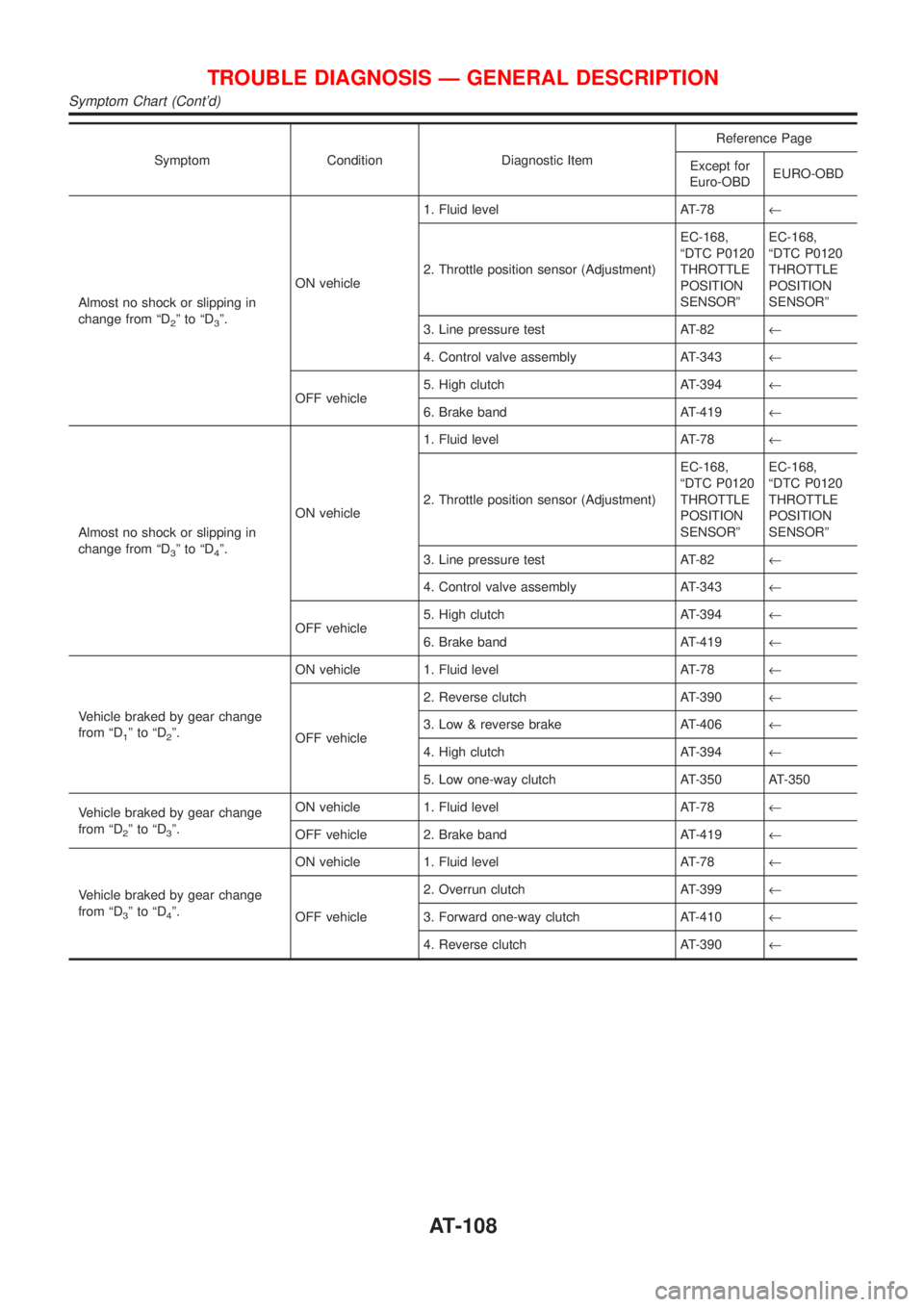
Symptom Condition Diagnostic ItemReference Page
Except for
Euro-OBDEURO-OBD
Almost no shock or slipping in
change from ªD
2ºtoªD3º.ON vehicle1. Fluid level AT-78¬
2. Throttle position sensor (Adjustment)EC-168,
ªDTC P0120
THROTTLE
POSITION
SENSORºEC-168,
ªDTC P0120
THROTTLE
POSITION
SENSORº
3. Line pressure test AT-82¬
4. Control valve assembly AT-343¬
OFF vehicle5. High clutch AT-394¬
6. Brake band AT-419¬
Almost no shock or slipping in
change from ªD
3ºtoªD4º.ON vehicle1. Fluid level AT-78¬
2. Throttle position sensor (Adjustment)EC-168,
ªDTC P0120
THROTTLE
POSITION
SENSORºEC-168,
ªDTC P0120
THROTTLE
POSITION
SENSORº
3. Line pressure test AT-82¬
4. Control valve assembly AT-343¬
OFF vehicle5. High clutch AT-394¬
6. Brake band AT-419¬
Vehicle braked by gear change
from ªD
1ºtoªD2º.ON vehicle 1. Fluid level AT-78¬
OFF vehicle2. Reverse clutch AT-390¬
3. Low & reverse brake AT-406¬
4. High clutch AT-394¬
5. Low one-way clutch AT-350 AT-350
Vehicle braked by gear change
from ªD
2ºtoªD3º.ON vehicle 1. Fluid level AT-78¬
OFF vehicle 2. Brake band AT-419¬
Vehicle braked by gear change
from ªD
3ºtoªD4º.ON vehicle 1. Fluid level AT-78¬
OFF vehicle2. Overrun clutch AT-399¬
3. Forward one-way clutch AT-410¬
4. Reverse clutch AT-390¬
TROUBLE DIAGNOSIS Ð GENERAL DESCRIPTION
Symptom Chart (Cont'd)
AT-108
Page 1296 of 2493
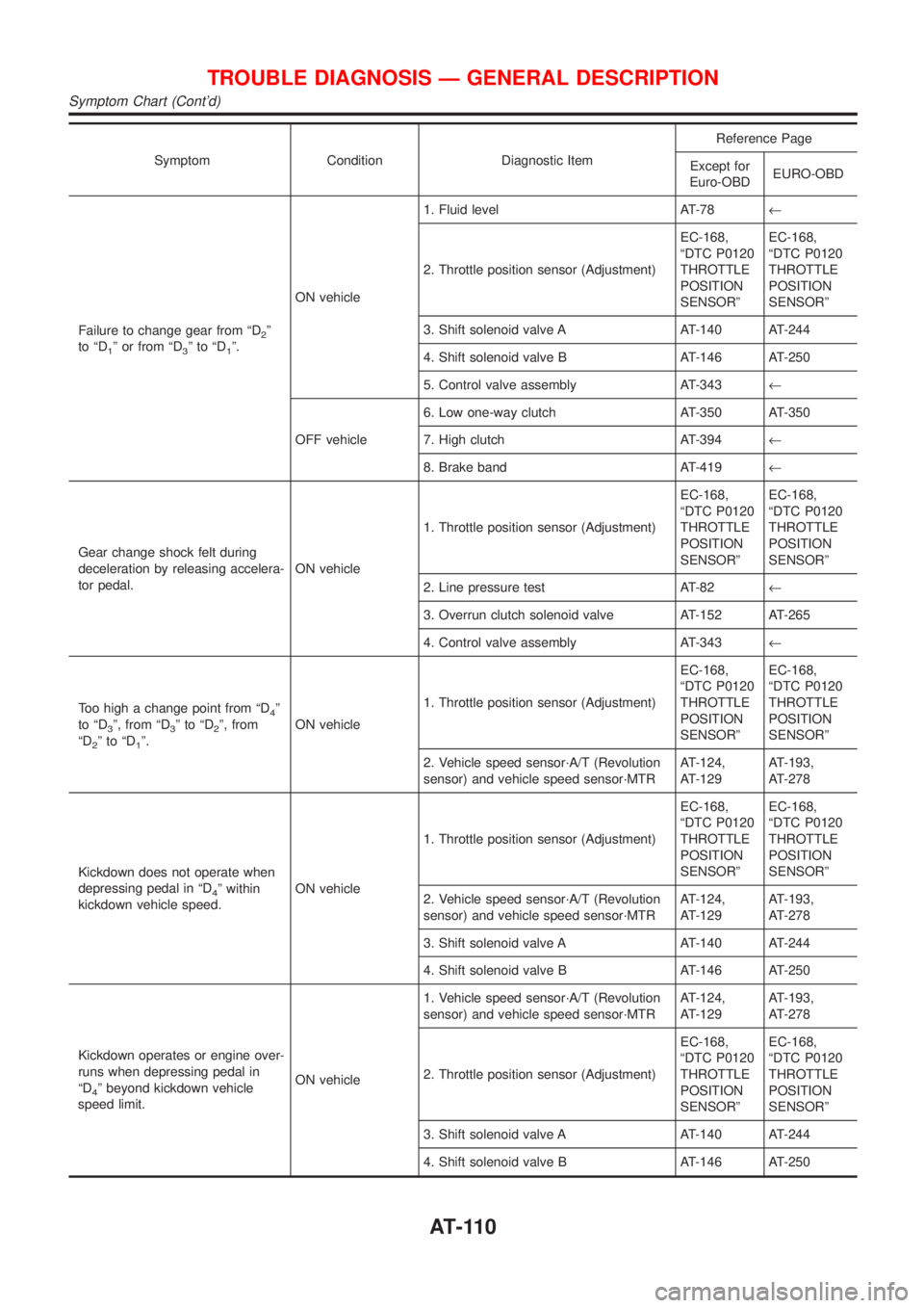
Symptom Condition Diagnostic ItemReference Page
Except for
Euro-OBDEURO-OBD
Failure to change gear from ªD
2º
to ªD
1º or from ªD3ºtoªD1º.ON vehicle1. Fluid level AT-78¬
2. Throttle position sensor (Adjustment)EC-168,
ªDTC P0120
THROTTLE
POSITION
SENSORºEC-168,
ªDTC P0120
THROTTLE
POSITION
SENSORº
3. Shift solenoid valve A AT-140 AT-244
4. Shift solenoid valve B AT-146 AT-250
5. Control valve assembly AT-343¬
OFF vehicle6. Low one-way clutch AT-350 AT-350
7. High clutch AT-394¬
8. Brake band AT-419¬
Gear change shock felt during
deceleration by releasing accelera-
tor pedal.ON vehicle1. Throttle position sensor (Adjustment)EC-168,
ªDTC P0120
THROTTLE
POSITION
SENSORºEC-168,
ªDTC P0120
THROTTLE
POSITION
SENSORº
2. Line pressure test AT-82¬
3. Overrun clutch solenoid valve AT-152 AT-265
4. Control valve assembly AT-343¬
Too high a change point from ªD
4º
to ªD
3º, from ªD3ºtoªD2º, from
ªD
2ºtoªD1º.ON vehicle1. Throttle position sensor (Adjustment)EC-168,
ªDTC P0120
THROTTLE
POSITION
SENSORºEC-168,
ªDTC P0120
THROTTLE
POSITION
SENSORº
2. Vehicle speed sensor´A/T (Revolution
sensor) and vehicle speed sensor´MTRAT-124,
AT-129AT-193,
AT-278
Kickdown does not operate when
depressing pedal in ªD
4º within
kickdown vehicle speed.ON vehicle1. Throttle position sensor (Adjustment)EC-168,
ªDTC P0120
THROTTLE
POSITION
SENSORºEC-168,
ªDTC P0120
THROTTLE
POSITION
SENSORº
2. Vehicle speed sensor´A/T (Revolution
sensor) and vehicle speed sensor´MTRAT-124,
AT-129AT-193,
AT-278
3. Shift solenoid valve A AT-140 AT-244
4. Shift solenoid valve B AT-146 AT-250
Kickdown operates or engine over-
runs when depressing pedal in
ªD
4º beyond kickdown vehicle
speed limit.ON vehicle1. Vehicle speed sensor´A/T (Revolution
sensor) and vehicle speed sensor´MTRAT-124,
AT-129AT-193,
AT-278
2. Throttle position sensor (Adjustment)EC-168,
ªDTC P0120
THROTTLE
POSITION
SENSORºEC-168,
ªDTC P0120
THROTTLE
POSITION
SENSORº
3. Shift solenoid valve A AT-140 AT-244
4. Shift solenoid valve B AT-146 AT-250
TROUBLE DIAGNOSIS Ð GENERAL DESCRIPTION
Symptom Chart (Cont'd)
AT-110
Page 1299 of 2493
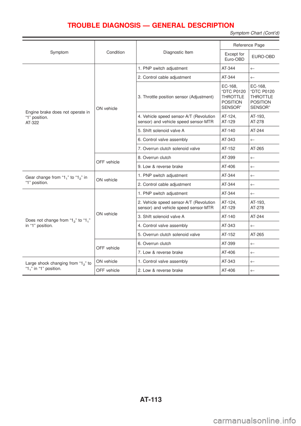
Symptom Condition Diagnostic ItemReference Page
Except for
Euro-OBDEURO-OBD
Engine brake does not operate in
ª1º position.
AT-322ON vehicle1. PNP switch adjustment AT-344¬
2. Control cable adjustment AT-344¬
3. Throttle position sensor (Adjustment)EC-168,
ªDTC P0120
THROTTLE
POSITION
SENSORºEC-168,
ªDTC P0120
THROTTLE
POSITION
SENSORº
4. Vehicle speed sensor´A/T (Revolution
sensor) and vehicle speed sensor´MTRAT-124,
AT-129AT-193,
AT-278
5. Shift solenoid valve A AT-140 AT-244
6. Control valve assembly AT-343¬
7. Overrun clutch solenoid valve AT-152 AT-265
OFF vehicle8. Overrun clutch AT-399¬
9. Low & reverse brake AT-406¬
Gear change from ª1
1ºtoª12ºin
ª1º position.ON vehicle1. PNP switch adjustment AT-344¬
2. Control cable adjustment AT-344¬
Does not change from ª1
2ºtoª11º
in ª1º position.ON vehicle1. PNP switch adjustment AT-344¬
2. Vehicle speed sensor´A/T (Revolution
sensor) and vehicle speed sensor´MTRAT-124,
AT-129AT-193,
AT-278
3. Shift solenoid valve A AT-140 AT-244
4. Control valve assembly AT-343¬
5. Overrun clutch solenoid valve AT-152 AT-265
OFF vehicle6. Overrun clutch AT-399¬
7. Low & reverse brake AT-406¬
Large shock changing from ª1
2ºto
ª1
1º in ª1º position.ON vehicle 1. Control valve assembly AT-343¬
OFF vehicle 2. Low & reverse brake AT-406¬
TROUBLE DIAGNOSIS Ð GENERAL DESCRIPTION
Symptom Chart (Cont'd)
AT-113
Page 1481 of 2493
5. Large Shock. ªNº®ªRº Position=NJAT0335SYMPTOM:
There is large shock when changing from ªNº to ªRº position.
1 CHECK SELF-DIAGNOSTIC RESULTS
Does self-diagnosis show damage to A/T fluid temperature sensor, line pressure solenoid valve or throttle position sensor
circuit?
SAT345HA
YesorNo
Ye s©+Check damaged circuit. Refer to the following items.
Except for Euro-OBD
+LINE PRESSURE SOLENOID VALVE: AT-174
+THROTTLE POSITION SENSOR: AT-132
+BATT/FLUID TEMP SEN (A/T FLUID TEMP SENSOR CIRCUIT AND TCM POWER
SOURCE: AT-163
Euro-OBD
+LINE PRESSURE SOLENOID VALVE: AT-237
+THROTTLE POSITION SENSOR: AT-256
+BATT/FLUID TEMP SEN (A/T FLUID TEMP SENSOR CIRCUIT AND TCM POWER
SOURCE: AT-271
No©GO TO 2.
2 CHECK THROTTLE POSITION SENSOR
Check throttle position sensor. Refer to EC-168, ªDTC P0120 THROTTLE POSITION SENSORº.
SAT004K
OK or NG
OK©GO TO 3.
NG©Repair or replace throttle position sensor.
TROUBLE DIAGNOSES FOR SYMPTOMS
5. Large Shock. ªNº®ªRº Position
AT-295
Page 1482 of 2493
3 CHECK LINE PRESSURE
Check line pressure at idle with selector lever in ªDº position. Refer to ªLine Pressure Testº, AT-82.
SAT494G
OK or NG
OK©GO TO 4.
NG©1. Remove control valve assembly. Refer to AT-343.
2. Check the following items:
+Valves to control line pressure (Pressure regulator valve, pressure modifier valve, pilot
valve and pilot filter)
+Line pressure solenoid valve
4 CHECK SYMPTOM
Check again.
OK or NG
OK©INSPECTION END
NG©1. Perform TCM input/output signal inspection.
2. If NG, recheck TCM pin terminals for damage or loose connection with harness con-
nector.
TROUBLE DIAGNOSES FOR SYMPTOMS
5. Large Shock. ªNº®ªRº Position (Cont'd)
AT-296
Page 1534 of 2493
SAT058K
*1: With gusset to A/T
*2: With gusset to cylinder block
SAT638A
5. Reinstall any part removed.
6. Adjust control cable. Refer to AT-344.
7. Check continuity of PNP switch. Refer to AT-326.
8. Refill transaxle with ATF and check fluid level.
9. Move selector lever through all positions to be sure that tran-
saxle operates correctly. With parking brake applied, idle
engine. Move selector lever through ªNº to ªDº, to ª2º, to ª1º and
ªRº positions. A slight shock should be felt through the hand
gripping the selector each time the transaxle is shifted.
10. Perform road test. Refer to AT-83.
REMOVAL AND INSTALLATION
Installation (Cont'd)
AT-348