Page 1219 of 2493
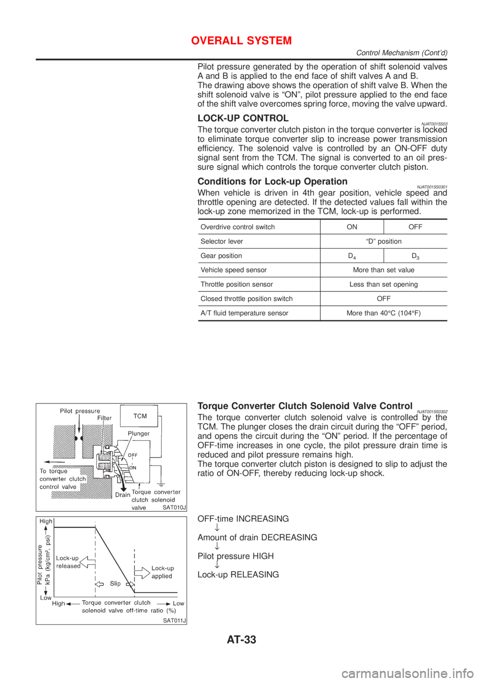
Pilot pressure generated by the operation of shift solenoid valves
A and B is applied to the end face of shift valves A and B.
The drawing above shows the operation of shift valve B. When the
shift solenoid valve is ªONº, pilot pressure applied to the end face
of the shift valve overcomes spring force, moving the valve upward.
LOCK-UP CONTROLNJAT0015S03The torque converter clutch piston in the torque converter is locked
to eliminate torque converter slip to increase power transmission
efficiency. The solenoid valve is controlled by an ON-OFF duty
signal sent from the TCM. The signal is converted to an oil pres-
sure signal which controls the torque converter clutch piston.
Conditions for Lock-up OperationNJAT0015S0301When vehicle is driven in 4th gear position, vehicle speed and
throttle opening are detected. If the detected values fall within the
lock-up zone memorized in the TCM, lock-up is performed.
Overdrive control switch ON OFF
Selector lever ªDº position
Gear position D
4D3
Vehicle speed sensor More than set value
Throttle position sensor Less than set opening
Closed throttle position switch OFF
A/T fluid temperature sensor More than 40ÉC (104ÉF)
SAT010J
Torque Converter Clutch Solenoid Valve ControlNJAT0015S0302The torque converter clutch solenoid valve is controlled by the
TCM. The plunger closes the drain circuit during the ªOFFº period,
and opens the circuit during the ªONº period. If the percentage of
OFF-time increases in one cycle, the pilot pressure drain time is
reduced and pilot pressure remains high.
The torque converter clutch piston is designed to slip to adjust the
ratio of ON-OFF, thereby reducing lock-up shock.
SAT011J
OFF-time INCREASING
¯
Amount of drain DECREASING
¯
Pilot pressure HIGH
¯
Lock-up RELEASING
OVERALL SYSTEM
Control Mechanism (Cont'd)
AT-33
Page 1220 of 2493
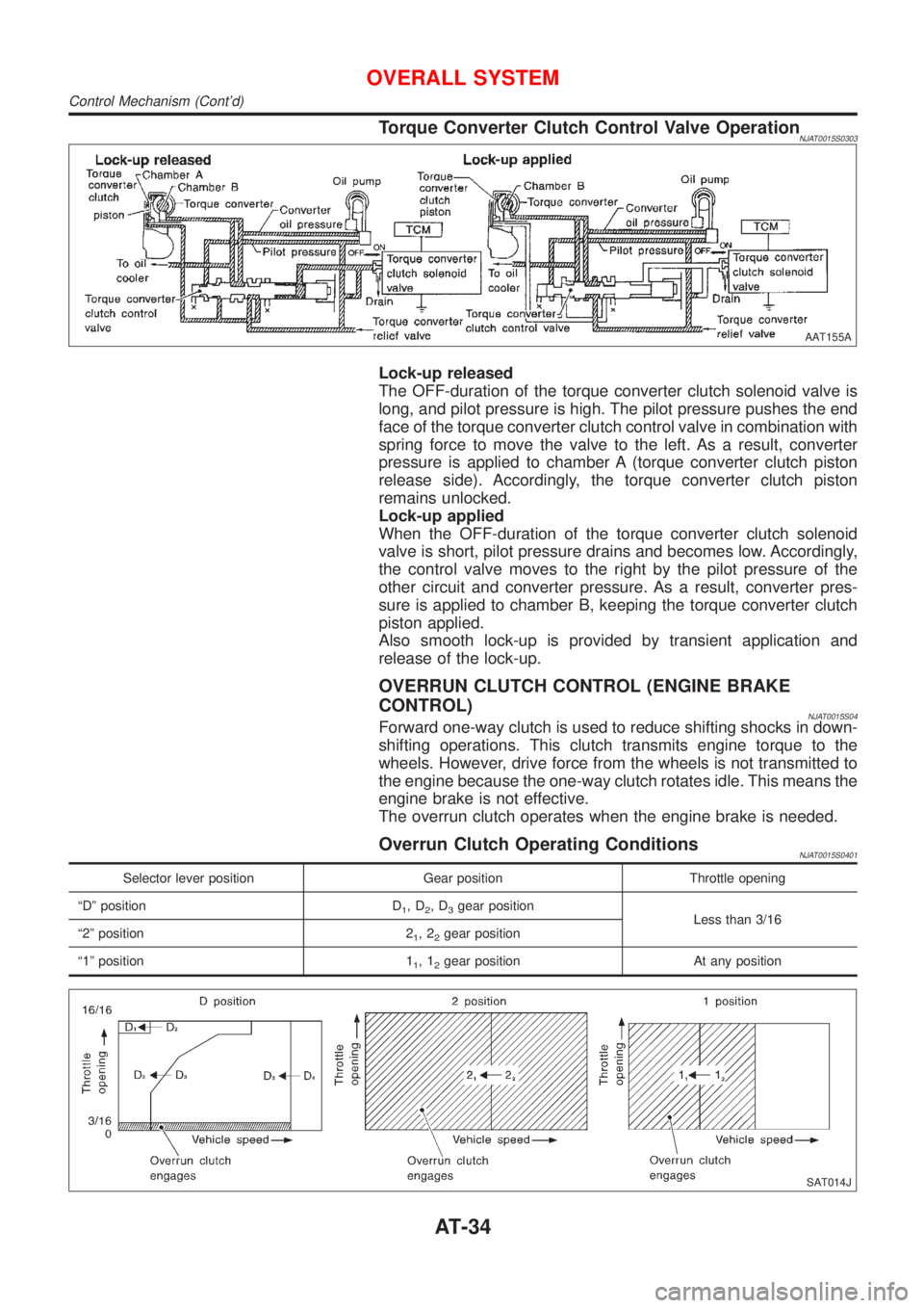
Torque Converter Clutch Control Valve OperationNJAT0015S0303
AAT155A
Lock-up released
The OFF-duration of the torque converter clutch solenoid valve is
long, and pilot pressure is high. The pilot pressure pushes the end
face of the torque converter clutch control valve in combination with
spring force to move the valve to the left. As a result, converter
pressure is applied to chamber A (torque converter clutch piston
release side). Accordingly, the torque converter clutch piston
remains unlocked.
Lock-up applied
When the OFF-duration of the torque converter clutch solenoid
valve is short, pilot pressure drains and becomes low. Accordingly,
the control valve moves to the right by the pilot pressure of the
other circuit and converter pressure. As a result, converter pres-
sure is applied to chamber B, keeping the torque converter clutch
piston applied.
Also smooth lock-up is provided by transient application and
release of the lock-up.
OVERRUN CLUTCH CONTROL (ENGINE BRAKE
CONTROL)
NJAT0015S04Forward one-way clutch is used to reduce shifting shocks in down-
shifting operations. This clutch transmits engine torque to the
wheels. However, drive force from the wheels is not transmitted to
the engine because the one-way clutch rotates idle. This means the
engine brake is not effective.
The overrun clutch operates when the engine brake is needed.
Overrun Clutch Operating ConditionsNJAT0015S0401
Selector lever position Gear position Throttle opening
ªDº position D
1,D2,D3gear position
Less than 3/16
ª2º position 2
1,22gear position
ª1º position 1
1,12gear position At any position
SAT014J
OVERALL SYSTEM
Control Mechanism (Cont'd)
AT-34
Page 1222 of 2493
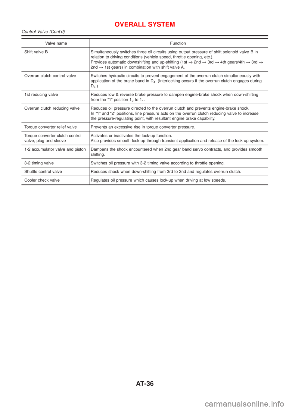
Valve name Function
Shift valve B Simultaneously switches three oil circuits using output pressure of shift solenoid valve B in
relation to driving conditions (vehicle speed, throttle opening, etc.).
Provides automatic downshifting and up-shifting (1st®2nd®3rd®4th gears/4th®3rd®
2nd®1st gears) in combination with shift valve A.
Overrun clutch control valve Switches hydraulic circuits to prevent engagement of the overrun clutch simultaneously with
application of the brake band in D
4. (Interlocking occurs if the overrun clutch engages during
D
4.)
1st reducing valve Reduces low & reverse brake pressure to dampen engine-brake shock when down-shifting
from the ª1º position 1
2to 11.
Overrun clutch reducing valve Reduces oil pressure directed to the overrun clutch and prevents engine-brake shock.
In ª1º and ª2º positions, line pressure acts on the overrun clutch reducing valve to increase
the pressure-regulating point, with resultant engine brake capability.
Torque converter relief valve Prevents an excessive rise in torque converter pressure.
Torque converter clutch control
valve, plug and sleeveActivates or inactivates the lock-up function.
Also provides smooth lock-up through transient application and release of the lock-up system.
1-2 accumulator valve and piston Dampens the shock encountered when 2nd gear band servo contracts, and provides smooth
shifting.
3-2 timing valve Switches oil pressure with 3-2 timing valve according to throttle opening.
Shuttle control valve Reduces shock when down-shifting from 3rd to 2nd and regulates overrun clutch.
Cooler check valve Regulates oil pressure which causes lock-up when driving at low speeds.
OVERALL SYSTEM
Control Valve (Cont'd)
AT-36
Page 1254 of 2493
DIAGNOSTIC WORKSHEET=NJAT0023S01Information from CustomerNJAT0023S0101KEY POINTS
WHAT..... Vehicle & A/T model
WHEN..... Date, Frequencies
WHERE..... Road conditions
HOW..... Operating conditions, Symptoms
Customer name MR/MS Model & Year VIN
Trans. model Engine Mileage
Incident Date Manuf. Date In Service Date
FrequencyNContinuousNIntermittent ( times a day)
SymptomsNVehicle does not move. (NAny positionNParticular position)
NNo up-shift (N1st®2ndN2nd®3rdN3rd®O/D)
NNo down-shift (NO/D®3rdN3rd®2ndN2nd®1st)
NLockup malfunction
NShift point too high or too low.
NShift shock or slip (NN®DNLockupNAny drive position)
NNoise or vibration
NNo kickdown
NNo pattern select
NOthers
()
O/D OFF indicator lamp Blinks for about 8 seconds.
NContinuously litNNot lit
Malfunction indicator (MI)NContinuously litNNot lit
TROUBLE DIAGNOSIS Ð
INTRODUCTION
EXCEPT FOR EURO-OBD
Introduction (Cont'd)
AT-68
Page 1255 of 2493
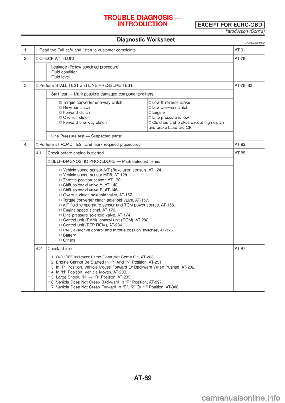
Diagnostic Worksheet=NJAT0023S0102
1.NRead the Fail-safe and listen to customer complaints. AT-9
2.NCHECK A/T FLUIDAT-78
NLeakage (Follow specified procedure)
NFluid condition
NFluid level
3.NPerform STALL TEST and LINE PRESSURE TEST. AT-78, 82
NStall test Ð Mark possible damaged components/others.
NTorque converter one-way clutch
NReverse clutch
NForward clutch
NOverrun clutch
NForward one-way clutchNLow & reverse brake
NLow one-way clutch
NEngine
NLine pressure is low
NClutches and brakes except high clutch
and brake band are OK
NLine Pressure test Ð Suspected parts:
4.NPerform all ROAD TEST and mark required procedures. AT-83
4-1. Check before engine is started. AT-85
NSELF-DIAGNOSTIC PROCEDURE Ð Mark detected items.
NVehicle speed sensor´A/T (Revolution sensor), AT-124.
NVehicle speed sensor´MTR, AT-129.
NThrottle position sensor, AT-132.
NShift solenoid valve A, AT-140.
NShift solenoid valve B, AT-146.
NOverrun clutch solenoid valve, AT-152.
NTorque converter clutch solenoid valve, AT-157.
NA/T fluid temperature sensor and TCM power source, AT-163.
NEngine speed signal, AT-170.
NLine pressure solenoid valve, AT-174.
NControl unit (RAM), control unit (ROM), AT-282.
NControl unit (EEP ROM), AT-284.
NPNP, overdrive control and throttle position switches, AT-326.
NBattery
NOthers
4-2. Check at idleAT-87
N1. O/D OFF Indicator Lamp Does Not Come On, AT-288.
N2. Engine Cannot Be Started In ªPº And ªNº Position, AT-291.
N3. In ªPº Position, Vehicle Moves Forward Or Backward When Pushed, AT-292.
N4. In ªNº Position, Vehicle Moves, AT-293.
N5. Large Shock. ªNº®ªRº Position, AT-295.
N6. Vehicle Does Not Creep Backward In ªRº Position, AT-297.
N7. Vehicle Does Not Creep Forward In ªDº, ª2º Or ª1º Position, AT-300.
TROUBLE DIAGNOSIS Ð
INTRODUCTION
EXCEPT FOR EURO-OBD
Introduction (Cont'd)
AT-69
Page 1259 of 2493
DIAGNOSTIC WORKSHEET=NJAT0257S01Information from CustomerNJAT0257S0101KEY POINTS
WHAT..... Vehicle & A/T model
WHEN..... Date, Frequencies
WHERE..... Road conditions
HOW..... Operating conditions, Symptoms
Customer name MR/MS Model & Year VIN
Trans. model Engine Mileage
Incident Date Manuf. Date In Service Date
FrequencyNContinuousNIntermittent ( times a day)
SymptomsNVehicle does not move. (NAny positionNParticular position)
NNo up-shift (N1st®2ndN2nd®3rdN3rd®O/D)
NNo down-shift (NO/D®3rdN3rd®2ndN2nd®1st)
NLockup malfunction
NShift point too high or too low.
NShift shock or slip (NN®DNLockupNAny drive position)
NNoise or vibration
NNo kickdown
NNo pattern select
NOthers
()
O/D OFF indicator lamp Blinks for about 8 seconds.
NContinuously litNNot lit
Malfunction indicator (MI)NContinuously litNNot lit
TROUBLE DIAGNOSIS Ð INTRODUCTIONEURO-OBD
Introduction (Cont'd)
AT-73
Page 1260 of 2493
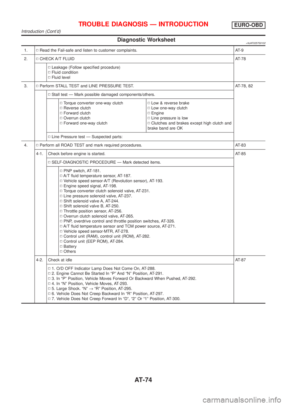
Diagnostic Worksheet=NJAT0257S0102
1.NRead the Fail-safe and listen to customer complaints. AT-9
2.NCHECK A/T FLUIDAT-78
NLeakage (Follow specified procedure)
NFluid condition
NFluid level
3.NPerform STALL TEST and LINE PRESSURE TEST. AT-78, 82
NStall test Ð Mark possible damaged components/others.
NTorque converter one-way clutch
NReverse clutch
NForward clutch
NOverrun clutch
NForward one-way clutchNLow & reverse brake
NLow one-way clutch
NEngine
NLine pressure is low
NClutches and brakes except high clutch and
brake band are OK
NLine Pressure test Ð Suspected parts:
4.NPerform all ROAD TEST and mark required procedures. AT-83
4-1. Check before engine is started. AT-85
NSELF-DIAGNOSTIC PROCEDURE Ð Mark detected items.
NPNP switch, AT-181.
NA/T fluid temperature sensor, AT-187.
NVehicle speed sensor´A/T (Revolution sensor), AT-193.
NEngine speed signal, AT-198.
NTorque converter clutch solenoid valve, AT-231.
NLine pressure solenoid valve, AT-237.
NShift solenoid valve A, AT-244.
NShift solenoid valve B, AT-250.
NThrottle position sensor, AT-256.
NOverrun clutch solenoid valve, AT-265.
NPNP, overdrive control and throttle position switches, AT-326.
NA/T fluid temperature sensor and TCM power source, AT-271.
NVehicle speed sensor´MTR, AT-278.
NControl unit (RAM), control unit (ROM), AT-282.
NControl unit (EEP ROM), AT-284.
NBattery
NOthers
4-2. Check at idleAT-87
N1. O/D OFF Indicator Lamp Does Not Come On, AT-288.
N2. Engine Cannot Be Started In ªPº And ªNº Position, AT-291.
N3. In ªPº Position, Vehicle Moves Forward Or Backward When Pushed, AT-292.
N4. In ªNº Position, Vehicle Moves, AT-293.
N5. Large Shock. ªNº®ªRº Position, AT-295.
N6. Vehicle Does Not Creep Backward In ªRº Position, AT-297.
N7. Vehicle Does Not Creep Forward In ªDº, ª2º Or ª1º Position, AT-300.
TROUBLE DIAGNOSIS Ð INTRODUCTIONEURO-OBD
Introduction (Cont'd)
AT-74
Page 1275 of 2493
5 CHECK SHIFT SHOCK
1. Apply foot brake.
SAT797A
2. Move selector lever to ªRº position.
SAT772B
3. Is there large shock when changing from ªNº to ªRº position?
YesorNo
Ye s©Mark the box on the DIAGNOSTIC WORKSHEET. Go to ª5. Large Shock ªNº®ªRº
Positionº, AT-295. Continue ROAD TEST.
No©GO TO 6.
6 CHECK VEHICLE MOVE
1. Release foot brake for several seconds.
SAT799A
2. Does vehicle creep backward when foot brake is released?
YesorNo
Ye s©GO TO 7.
No©Mark the box on the DIAGNOSTIC WORKSHEET. Go to ª6. Vehicle Does Not Creep
Backward In ªRº Positionº, AT-297. Continue ROAD TEST.
TROUBLE DIAGNOSIS Ð BASIC INSPECTION
Road Test (Cont'd)
AT-89