Page 144 of 2493

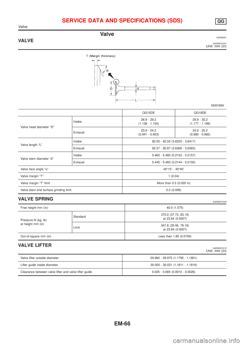
ValveNJEM0031VALVENJEM0031S01Unit: mm (in)
SEM188A
QG15DE QG18DE
Valve head diameter ªDºIntake28.9 - 29.2
(1.138 - 1.150)29.9 - 30.2
(1.177 - 1.189)
Exhaust23.9 - 24.2
(0.941 - 0.953)24.9 - 25.2
(0.980 - 0.992)
Valve length ªLºIntake 92.00 - 92.50 (3.6220 - 3.6417)
Exhaust 92.37 - 92.87 (3.6366 - 3.6563)
Valve stem diameter ªdºIntake 5.465 - 5.480 (0.2152 - 0.2157)
Exhaust 5.445 - 5.460 (0.2144 - 0.2150)
Valve face angle ªaº45É15¢- 45É45¢
Valve margin ªTº1 (0.04)
Valve margin ªTº limitMore than 0.5 (0.020 in)
Valve stem end surface grinding limit 0.2 (0.008)
VALVE SPRINGNJEM0031S02
Free height mm (in)40.0 (1.575)
Pressure N (kg, lb)
at height mm (in)Standard370.0 (37.73, 83.19)
at 23.64 (0.9307)
Limit347.8 (35.46, 78.19)
at 23.64 (0.9307)
Out-of-square mm (in)Less than 1.80 (0.0709)
VALVE LIFTERNJEM0031S10Unit: mm (in)
Valve lifter outside diameter 29.960 - 29.975 (1.1795 - 1.1801)
Lifter guide inside diameter 30.000 - 30.021 (1.1811 - 1.1819)
Clearance between valve lifter and valve lifter guide 0.025 - 0.065 (0.0010 - 0.0026)
SERVICE DATA AND SPECIFICATIONS (SDS)QG
Valve
EM-66
Page 145 of 2493

VALVE CLEARANCE=NJEM0031S11Unit: mm (in)
For adjusting For checking
Hot Cold* (reference data) Hot
Intake 0.32 - 0.40 (0.013 - 0.016) 0.25 - 0.33 (0.010 - 0.013) 0.21 - 0.49 (0.008 - 0.019)
Exhaust 0.37 - 0.45 (0.015 - 0.018) 0.32 - 0.40 (0.013 - 0.016) 0.30 - 0.58 (0.012 - 0.023)
*: At a temperature of approximately 20ÉC (68ÉF)
Whenever valve clearances are adjusted to cold specifications, check that the clearances satisfy hot specifications and adjust
again if necessary.
VALVE GUIDENJEM0031S04Unit: mm (in)
MEM096A
Intake Exhaust
Standard Service Standard Service
Valve guideOuter diameter9.523 - 9.534
(0.3749 - 0.3754)9.723 - 9.734
(0.3828 - 0.3832)9.523 - 9.534
(0.3749 - 0.3754)9.723 - 9.734
(0.3828 - 0.3832)
Inner diameter
[Finished size]5.500 - 5.515 (0.2165 - 0.2171) 5.500 - 5.515 (0.2165 - 0.2171)
Cylinder head valve guide hole diameter9.475 - 9.496
(0.3730 - 0.3739)9.685 - 9.696
(0.3813 - 0.3817)9.475 - 9.496
(0.3730 - 0.3739)9.685 - 9.696
(0.3813 - 0.3817)
Interference fit of valve guide0.027 - 0.059
(0.0011 - 0.0023)0.027 - 0.049
(0.0011 - 0.0019)0.027 - 0.059
(0.0011 - 0.0023)0.027 - 0.049
(0.0011 - 0.0019)
Stem to guide clearance 0.020 - 0.050 (0.0008 - 0.0020) 0.040 - 0.070 (0.0016 - 0.0028)
Valve deflection limit (Dial gauge reading) 0.2 (0.008)
Projection length ªLº 11.5 - 11.7 (0.453 - 0.461)
AVAILABLE SHIMSNJEM0031S07
Thickness mm (in) Identification mark
2.00 (0.0787) 200
2.02 (0.0795) 202
2.04 (0.0803) 204
2.06 (0.0811) 206
2.08 (0.0819) 208
2.10 (0.0827) 210
2.12 (0.0835) 212
2.14 (0.0843) 214
2.16 (0.0850) 216
SERVICE DATA AND SPECIFICATIONS (SDS)QG
Valve (Cont'd)
EM-67
Page 149 of 2493
VALVE SEAT RESURFACE LIMITNJEM0031S08Unit: mm (in)
AEM343
Depth (L)Intake 35.95 - 36.55 (1.4154 - 1.4390)
Exhaust 35.92 - 36.52 (1.4142 - 1.4378)
Camshaft and Camshaft BearingNJEM0032Unit: mm (in)
Engine modelQG
Cam height ªAºIntake 40.610 - 40.800 (1.5988 - 1.6063)
Exhaust 40.056 - 40.246 (1.5770 - 1.5845)
Cam wear limit0.20 (0.0079)
EM671
Standard Limit
Camshaft journal to bearing clearance 0.045 - 0.086 (0.0018 - 0.0034) 0.15 (0.0059)
Inner diameter of camshaft bearingNo. 1 28.000 - 28.021 (1.1024 - 1.1032)
Ð
No. 2 to No. 5 24.000 - 24.021 (0.9449 - 0.9457)
Outer diameter of camshaft journalNo. 1 27.935 - 27.955 (1.0998 - 1.1006)
Ð
No. 2 to No. 5 23.935 - 23.955 (0.9423 - 0.9431)
Camshaft runout [TIR*] Less than 0.02 (0.0008) 0.1 (0.004)
Camshaft end play 0.115 - 0.188 (0.0045 - 0.0074) 0.20 (0.0079)
*Total indicator reading
SERVICE DATA AND SPECIFICATIONS (SDS)QG
Valve (Cont'd)
EM-71
Page 150 of 2493
Cylinder BlockNJEM0033Unit: mm (in)
SEM171D
QG15DE QG18DE
Limit
Standard
Surface flatness Less than 0.03 (0.0012) 0.1 (0.004)
Height ªHº (nominal) 213.95 - 214.05 (8.4232 - 8.4271) Ð
Cylinder bore
inner diameterStandardGrade No. 1 73.600 - 73.610 (2.8976 - 2.8976) 80.000 - 80.010 (3.1496 - 3.1500)
0.2 (0.008) Grade No. 2 73.610 - 73.620 (2.8980 - 2.8984) 80.010 - 80.020 (3.1500 - 3.1504)
Grade No. 3 73.620 - 73.630 (2.8984 - 2.8988) 80.020 - 80.030 (3.1504 - 3.1508)
Out-of-round (X þ Y) Less than 0.015 (0.0006) Ð
Taper (A þ B) Less than 0.01 (0.0004) Ð
Difference in inner diameter between cylinders 0.05 (0.0020) 0.2 (0.008)
SERVICE DATA AND SPECIFICATIONS (SDS)QG
Cylinder Block
EM-72
Page 151 of 2493

Piston, Piston Ring and Piston Pin=NJEM0034PISTONNJEM0034S01Unit: mm (in)
SEM882E
QG15DE QG18DE
Piston skirt
diameter ªAºStandardGrade No. 1 73.575 - 73.585 (2.8966 - 2.8970) 79.965 - 79.975 (3.1482 - 3.1486)
Grade No. 2 73.585 - 73.595 (2.8970 - 2.8974) 79.975 - 79.985 (3.1486 - 3.1490)
Grade No. 3 73.595 - 73.605 (2.8974 - 2.8978) 79.985 - 79.995 (3.1490 - 3.1494)
0.5 (0.002) oversize (service) 74.075 - 74.105 (2.9163 - 2.9175) 80.215 - 80.245 (3.1581 - 3.1592)*1
1.0 (0.039) oversize (service) 74.575 - 74.605 (2.9360 - 2.9372) 80.465 - 80.495 (3.1679 - 3.1691)*2
ªaº dimension 43.6 (1.717) 42.3 (1.665)
Piston pin hole inner diameter 18.987 - 18.999 (0.7475 - 0.7080) 18.993 - 19.005 (0.7478 - 0.7482)
Piston to bore clearance 0.015 - 0.035 (0.0006 - 0.0014) 0.025 - 0.045 (0.0010 - 0.0018)
*1: 0.25 (0.0098) oversize (service)
*2: 0.5 (0.002) oversize (service)
PISTON RINGNJEM0034S02Unit: mm (in)
QG15DE QG18DE
Limit
Standard
Side clearanceTop 0.045 - 0.080 (0.0018 - 0.0031) 0.040 - 0.080 (0.0016 - 0.0031) 0.110 (0.0043)
2nd 0.030 - 0.070 (0.0012 - 0.0028) 0.100 (0.0039)
Oil 0.065 - 0.135 (0.0026 - 0.0053) 0.045 - 0.155 (0.0018 - 0.0061) Ð
End gapTop 0.20 - 0.30 (0.0079 - 0.0118) 0.53 (0.0209)
2nd 0.32 - 0.47 (0.0126 - 0.0185) 0.67 (0.0264)
Oil 0.20 - 0.60 (0.0079 - 0.0236) 0.95 (0.0374)
PISTON PINNJEM0034S03Unit: mm (in)
QG15DE QG18DE
Piston pin outer diameter 18.989 - 19.001 (0.7476 - 0.7481)
Piston pin to piston clearance þ0.004 to 0 (þ0.0002 to 0) 0.002 - 0.006 (0.0001 - 0.0002)
Piston pin to connecting rod bushing
clearanceStandard 0.005 - 0.017 (0.0002 - 0.0007)
Limit 0.023 (0.0009)
SERVICE DATA AND SPECIFICATIONS (SDS)QG
Piston, Piston Ring and Piston Pin
EM-73
Page 152 of 2493
![NISSAN ALMERA N16 2001 Electronic Repair Manual Connecting RodNJEM0035Unit: mm (in)
Center distance140.45 - 140.55 (5.5295 - 5.5335)
Bend limit [per 100 (3.94)]0.15 (0.0059)
Torsion limit [per 100 (3.94)]0.3 (0.012)
Connecting rod bushing inner dia NISSAN ALMERA N16 2001 Electronic Repair Manual Connecting RodNJEM0035Unit: mm (in)
Center distance140.45 - 140.55 (5.5295 - 5.5335)
Bend limit [per 100 (3.94)]0.15 (0.0059)
Torsion limit [per 100 (3.94)]0.3 (0.012)
Connecting rod bushing inner dia](/manual-img/5/57351/w960_57351-151.png)
Connecting RodNJEM0035Unit: mm (in)
Center distance140.45 - 140.55 (5.5295 - 5.5335)
Bend limit [per 100 (3.94)]0.15 (0.0059)
Torsion limit [per 100 (3.94)]0.3 (0.012)
Connecting rod bushing inner diameter* (small end) 19.000 - 19.012 (0.7480 - 0.7485)
Connecting rod big end inner diameter 43.000 - 43.013 (1.6929 - 1.6934)
Side clearanceStandard 0.200 - 0.470 (0.0079 - 0.0185)
Limit 0.5 (0.020)
*After installing in connecting rod
CrankshaftNJEM0036Unit: mm (in)
Main journal dia. ªDmºGrade No. 0 49.956 - 49.964 (1.9668 - 1.9671)
Grade No. 1 49.948 - 49.956 (1.9665 - 1.9668)
Grade No. 2 49.940 - 49.948 (1.9661 - 1.9665)
Pin journal dia. ªDpºGrade No. 0 39.968 - 39.974 (1.5735 - 1.5738)
Grade No. 1 39.962 - 39.968 (1.5733 - 1.5735)
Grade No. 2 39.956 - 39.962 (1.5731 - 1.5733)
Center distance ªrº43.95 - 44.05 (1.7303 - 1.7342)
Out-of-round (X þ Y)Standard Less than 0.003 (0.0001)
Limit Less than 0.005 (0.0002)
Taper (A þ B)Standard Less than 0.004 (0.0002)
Limit Less than 0.005 (0.0002)
Runout [TIR*]Standard Less than 0.04 (0.0016)
Limit Less than 0.05 (0.0020)
Free end playStandard 0.060 - 0.260 (0.0024 - 0.0102)
Limit 0.3 (0.012)
*: Total indicator reading
Main BearingNJEM0037STANDARDNJEM0037S01
Grade No. Thickness ªTº mm (in) Identification color
0 1.826 - 1.830 (0.0719 - 0.0720) Black
1 1.830 - 1.834 (0.0720 - 0.0722) Red
2 1.834 - 1.838 (0.0722 - 0.0724) Green
3 1.838 - 1.842 (0.0724 - 0.0725) Yellow
4 1.842 - 1.846 (0.0725 - 0.0727) Blue
UNDERSIZENJEM0037S02Unit: mm (in)
Thickness ªTº
0.25 (0.0098) 1.960 - 1.964 (0.0772 - 0.0773)
0.50 (0.0197) 2.085 - 2.089 (0.0821 - 0.0822)
SERVICE DATA AND SPECIFICATIONS (SDS)QG
Connecting Rod
EM-74
Page 154 of 2493

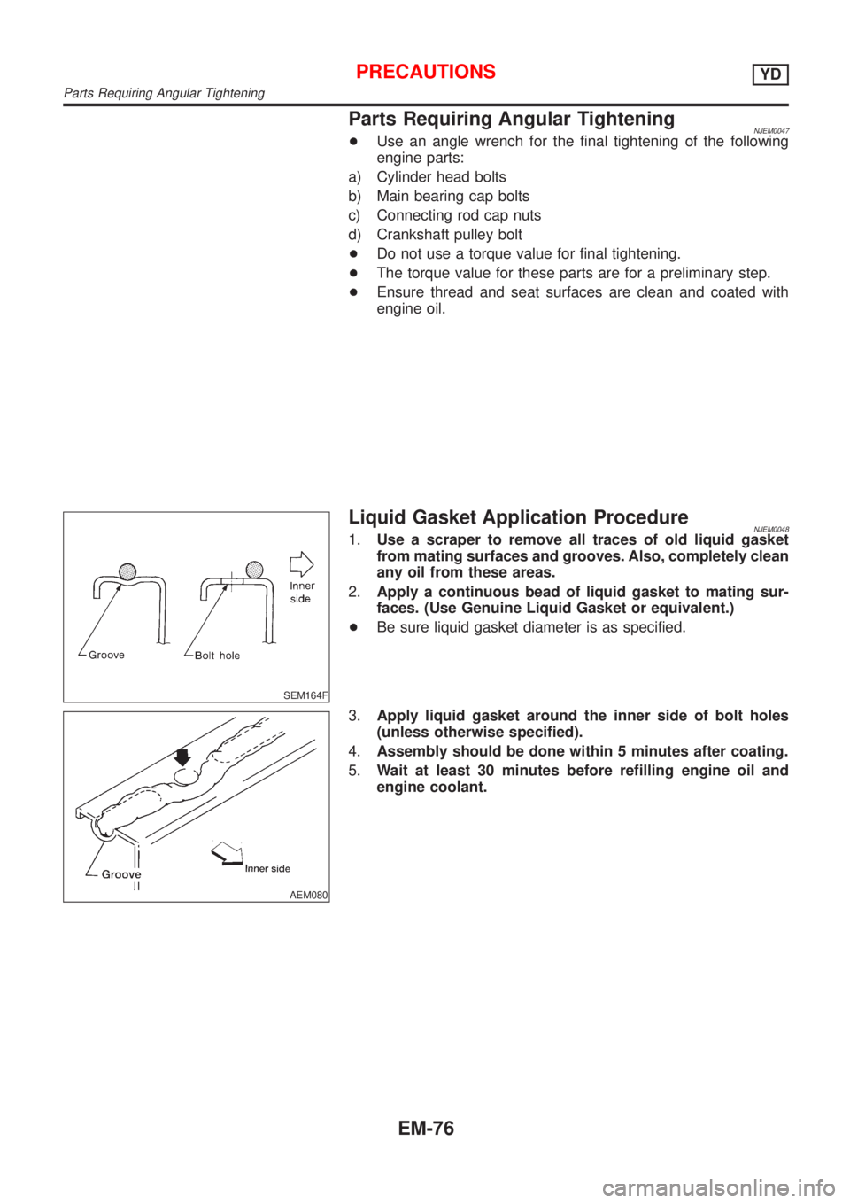
Parts Requiring Angular TighteningNJEM0047+Use an angle wrench for the final tightening of the following
engine parts:
a) Cylinder head bolts
b) Main bearing cap bolts
c) Connecting rod cap nuts
d) Crankshaft pulley bolt
+Do not use a torque value for final tightening.
+The torque value for these parts are for a preliminary step.
+Ensure thread and seat surfaces are clean and coated with
engine oil.
SEM164F
Liquid Gasket Application ProcedureNJEM00481.Use a scraper to remove all traces of old liquid gasket
from mating surfaces and grooves. Also, completely clean
any oil from these areas.
2.Apply a continuous bead of liquid gasket to mating sur-
faces. (Use Genuine Liquid Gasket or equivalent.)
+Be sure liquid gasket diameter is as specified.
AEM080
3.Apply liquid gasket around the inner side of bolt holes
(unless otherwise specified).
4.Assembly should be done within 5 minutes after coating.
5.Wait at least 30 minutes before refilling engine oil and
engine coolant.
PRECAUTIONSYD
Parts Requiring Angular Tightening
EM-76
Page 168 of 2493

JEM116G
13. For Europe only, remove catalyst rear diffuser, EM-109, ªCata-
lyst (For Europe)º.
14. Remove upper oil pan bolts in reverse order.
15. Remove four engine-to-transaxle bolts using a universal
socket. (Commercial Service Tool).
16. Remove upper oil pan.
a. Insert an appropriate size tool into the notch of upper oil pan.
+Be careful not to damage aluminum mating surface.
+Do not insert screwdriver, or oil pan flange will be
deformed.
b. Pry off upper oil pan by moving the tool up and down.
c. Remove upper oil pan.
+Be careful to prevent No. 15 and 16 blots from falling into
transaxle case.
JEM117G
InstallationNJEM00561. Install upper oil pan.
a. Use a scraper to remove old liquid gasket from mating sur-
faces.
+Also remove old liquid gasket from mating surface of cyl-
inder block, front cover and lower oil pan.
+Remove old liquid gasket from the bolt hole and thread.
SEM159F
b. Apply a continuous bead of liquid gasket to mating surface of
aluminum oil pan.
+Use Genuine Liquid Gasket or equivalent.
JEM118G
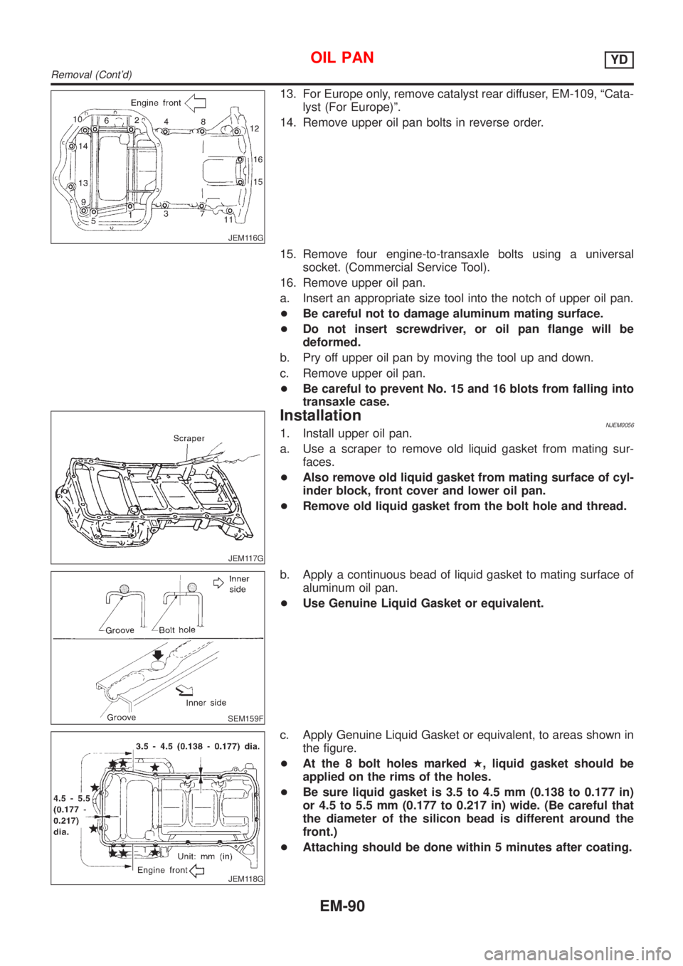
c. Apply Genuine Liquid Gasket or equivalent, to areas shown in
the figure.
+At the 8 bolt holes markedH, liquid gasket should be
applied on the rims of the holes.
+Be sure liquid gasket is 3.5 to 4.5 mm (0.138 to 0.177 in)
or 4.5 to 5.5 mm (0.177 to 0.217 in) wide. (Be careful that
the diameter of the silicon bead is different around the
front.)
+Attaching should be done within 5 minutes after coating.
OIL PANYD
Removal (Cont'd)
EM-90