Page 245 of 2493

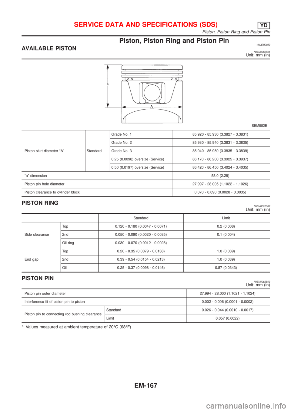
Piston, Piston Ring and Piston Pin=NJEM0082AVAILABLE PISTONNJEM0082S01Unit: mm (in)
SEM882E
Piston skirt diameter ªAº StandardGrade No. 1 85.920 - 85.930 (3.3827 - 3.3831)
Grade No. 2 85.930 - 85.940 (3.3831 - 3.3835)
Grade No. 3 85.940 - 85.950 (3.3835 - 3.3839)
0.25 (0.0098) oversize (Service) 86.170 - 86.200 (3.3925 - 3.3937)
0.50 (0.0197) oversize (Service) 86.420 - 86.450 (3.4024 - 3.4035)
ªaº dimension58.0 (2.28)
Piston pin hole diameter27.997 - 28.005 (1.1022 - 1.1026)
Piston clearance to cylinder block 0.070 - 0.090 (0.0028 - 0.0035)
PISTON RINGNJEM0082S02Unit: mm (in)
Standard Limit
Side clearanceTop 0.120 - 0.180 (0.0047 - 0.0071) 0.2 (0.008)
2nd 0.050 - 0.090 (0.0020 - 0.0035) 0.1 (0.004)
Oil ring 0.030 - 0.070 (0.0012 - 0.0028) Ð
End gapTop 0.20 - 0.35 (0.0079 - 0.0138) 1.0 (0.039)
2nd 0.39 - 0.54 (0.0154 - 0.0213) 1.0 (0.039)
Oil 0.25 - 0.37 (0.0098 - 0.0146) 0.87 (0.0343)
PISTON PINNJEM0082S03Unit: mm (in)
Piston pin outer diameter27.994 - 28.000 (1.1021 - 1.1024)
Interference fit of piston pin to piston 0.002 - 0.006 (0.0001 - 0.0002)
Piston pin to connecting rod bushing clearanceStandard 0.026 - 0.044 (0.0010 - 0.0017)
Limit 0.057 (0.0022)
*: Values measured at ambient temperature of 20ÉC (68ÉF)
SERVICE DATA AND SPECIFICATIONS (SDS)YD
Piston, Piston Ring and Piston Pin
EM-167
Page 246 of 2493
![NISSAN ALMERA N16 2001 Electronic Repair Manual Connecting RodNJEM0083Unit: mm (in)
Center distance157.5 (6.201)
Bend [per 100 (3.94)] Limit 0.12 (0.0047)
Torsion [per 100 (3.94)] Limit 0.12 (0.0047)
Connecting rod small end inner diameter 30.080 - NISSAN ALMERA N16 2001 Electronic Repair Manual Connecting RodNJEM0083Unit: mm (in)
Center distance157.5 (6.201)
Bend [per 100 (3.94)] Limit 0.12 (0.0047)
Torsion [per 100 (3.94)] Limit 0.12 (0.0047)
Connecting rod small end inner diameter 30.080 -](/manual-img/5/57351/w960_57351-245.png)
Connecting RodNJEM0083Unit: mm (in)
Center distance157.5 (6.201)
Bend [per 100 (3.94)] Limit 0.12 (0.0047)
Torsion [per 100 (3.94)] Limit 0.12 (0.0047)
Connecting rod small end inner diameter 30.080 - 31.000 (1.1842 - 1.2205)
Piston pin bushing inner diameter* 28.026 - 28.038 (1.1034 - 1.1039)
Connecting rod big end inner diameter 55.000 - 55.013 (2.1654 - 2.1659)
Side clearanceStandard 0.200 - 0.350 (0.0079 - 0.0138)
Limit 0.4 (0.016)
*: After installing in connecting rod
CrankshaftNJEM0084Unit: mm (in)
Main journal dia. ªDmº gradeGrade No. 0
Grade No. 1
Grade No. 262.967 - 62.975 (2.4790 - 2.4793)
62.959 - 62.967 (2.4787 - 2.4790)
62.951 - 62.959 (2.4784 - 2.4787)
Pin journal dia. ªDpºGrade No. 0 51.968 - 51.974 (2.0460 - 2.0462)
Grade No. 1 51.961 - 51.968 (2.0457 - 2.0460)
Grade No. 2 51.954 - 51.961 (2.0454 - 2.0457)
Center distance ªrº46.97 - 47.03 (1.8492 - 1.8516)
Out-of-round (X þ Y) Standard/Limit Less than 0.003 (0.0001)/Less than 0.005 (0.0002)
Taper (A þ B) Standard/Limit Less than 0.003 (0.0001)/Less than 0.005 (0.0002)
Runout [TIR*]Standard Less than 0.05 (0.0020)
Limit Less than 0.10 (0.0039)
Free end playStandard 0.10 - 0.25 (0.0039 - 0.0098)
Limit 0.30 (0.0118)
SEM645EM715
*: Total indicator reading
SERVICE DATA AND SPECIFICATIONS (SDS)YD
Connecting Rod
EM-168
Page 247 of 2493

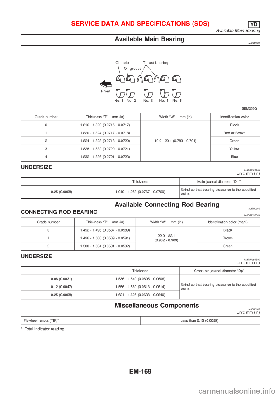
Available Main BearingNJEM0085
SEM255G
Grade number Thickness ªTº mm (in) Width ªWº mm (in) Identification color
0 1.816 - 1.820 (0.0715 - 0.0717)
19.9 - 20.1 (0.783 - 0.791)Black
1 1.820 - 1.824 (0.0717 - 0.0718) Red or Brown
2 1.824 - 1.828 (0.0718 - 0.0720) Green
3 1.828 - 1.832 (0.0720 - 0.0721) Yellow
4 1.832 - 1.836 (0.0721 - 0.0723) Blue
UNDERSIZENJEM0085S01Unit: mm (in)
Thickness Main journal diameter ªDmº
0.25 (0.0098) 1.949 - 1.953 (0.0767 - 0.0769)Grind so that bearing clearance is the specified
value.
Available Connecting Rod BearingNJEM0086CONNECTING ROD BEARINGNJEM0086S01
Grade number Thickness ªTº mm (in) Width ªWº mm (in) Identification color (mark)
0 1.492 - 1.496 (0.0587 - 0.0589)
22.9 - 23.1
(0.902 - 0.909)Black
1 1.496 - 1.500 (0.0589 - 0.0591) Brown
2 1.500 - 1.504 (0.0591 - 0.0592) Green
UNDERSIZENJEM0086S02Unit: mm (in)
Thickness Crank pin journal diameter ªDpº
0.08 (0.0031) 1.536 - 1.540 (0.0605 - 0.0606)
Grind so that bearing clearance is the specified
value. 0.12 (0.0047) 1.556 - 1.560 (0.0613 - 0.0614)
0.25 (0.0098) 1.621 - 1.625 (0.0638 - 0.0640)
Miscellaneous ComponentsNJEM0087Unit: mm (in)
Flywheel runout [TIR]*Less than 0.15 (0.0059)
*: Total indicator reading
SERVICE DATA AND SPECIFICATIONS (SDS)YD
Available Main Bearing
EM-169
Page 251 of 2493

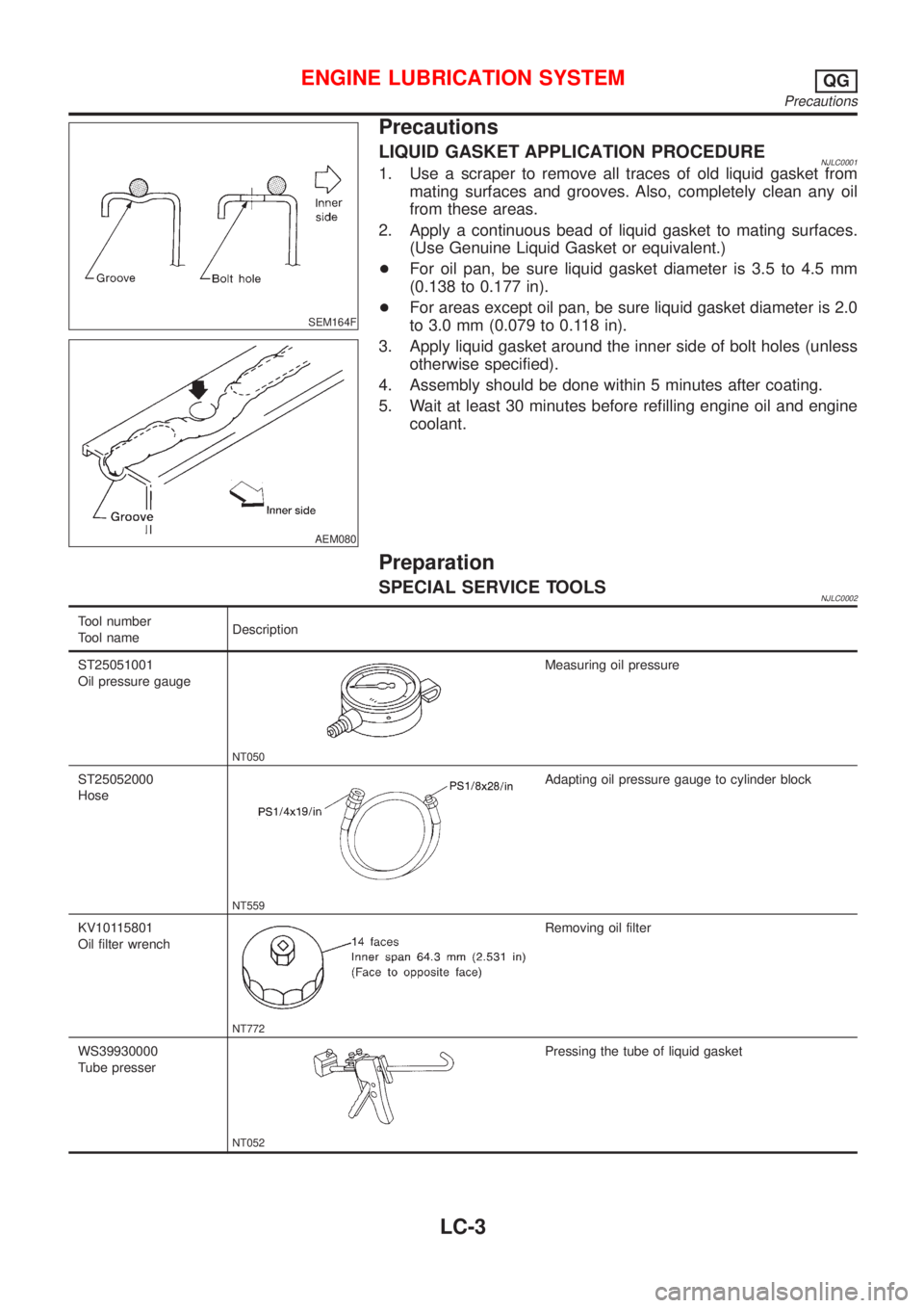
SEM164F
AEM080
Precautions
LIQUID GASKET APPLICATION PROCEDURENJLC00011. Use a scraper to remove all traces of old liquid gasket from
mating surfaces and grooves. Also, completely clean any oil
from these areas.
2. Apply a continuous bead of liquid gasket to mating surfaces.
(Use Genuine Liquid Gasket or equivalent.)
+For oil pan, be sure liquid gasket diameter is 3.5 to 4.5 mm
(0.138 to 0.177 in).
+For areas except oil pan, be sure liquid gasket diameter is 2.0
to 3.0 mm (0.079 to 0.118 in).
3. Apply liquid gasket around the inner side of bolt holes (unless
otherwise specified).
4. Assembly should be done within 5 minutes after coating.
5. Wait at least 30 minutes before refilling engine oil and engine
coolant.
Preparation
SPECIAL SERVICE TOOLSNJLC0002
Tool number
Tool nameDescription
ST25051001
Oil pressure gauge
NT050
Measuring oil pressure
ST25052000
Hose
NT559
Adapting oil pressure gauge to cylinder block
KV10115801
Oil filter wrench
NT772
Removing oil filter
WS39930000
Tube presser
NT052
Pressing the tube of liquid gasket
ENGINE LUBRICATION SYSTEMQG
Precautions
LC-3
Page 259 of 2493

SEM164F
AEM080
Precautions
LIQUID GASKET APPLICATION PROCEDURENJLC00141. Use a scraper to remove all traces of old liquid gasket from
mating surfaces and grooves. Also, completely clean any oil
from these areas.
2. Apply a continuous bead of liquid gasket to mating surfaces.
(Use Genuine Liquid Gasket or equivalent.)
+For oil pan, be sure liquid gasket diameter is 3.5 to 4.5 mm
(0.138 to 0.177 in).
+For areas except oil pan, be sure liquid gasket diameter is 2.0
to 3.0 mm (0.079 to 0.118 in).
3. Apply liquid gasket around the inner side of bolt holes (unless
otherwise specified).
4. Assembly should be done within 5 minutes after coating.
5. Wait at least 30 minutes before refilling engine oil and engine
coolant.
Preparation
SPECIAL SERVICE TOOLSNJLC0015
Tool number
Tool nameDescription
EG17650301
Radiator cap tester
adapter
NT564
Adapting radiator cap tester to radiator filler neck
a: 28 (1.10) dia.
b: 31.4 (1.236) dia.
c: 41.3 (1.626) dia.
Unit: mm (in)
KV99103510
Radiator plate pliers A
NT224
Installing radiator upper and lower tanks
KV99103520
Radiator plate pliers B
NT225
Removing radiator upper and lower tanks
ENGINE COOLING SYSTEMQG
Precautions
LC-11
Page 273 of 2493

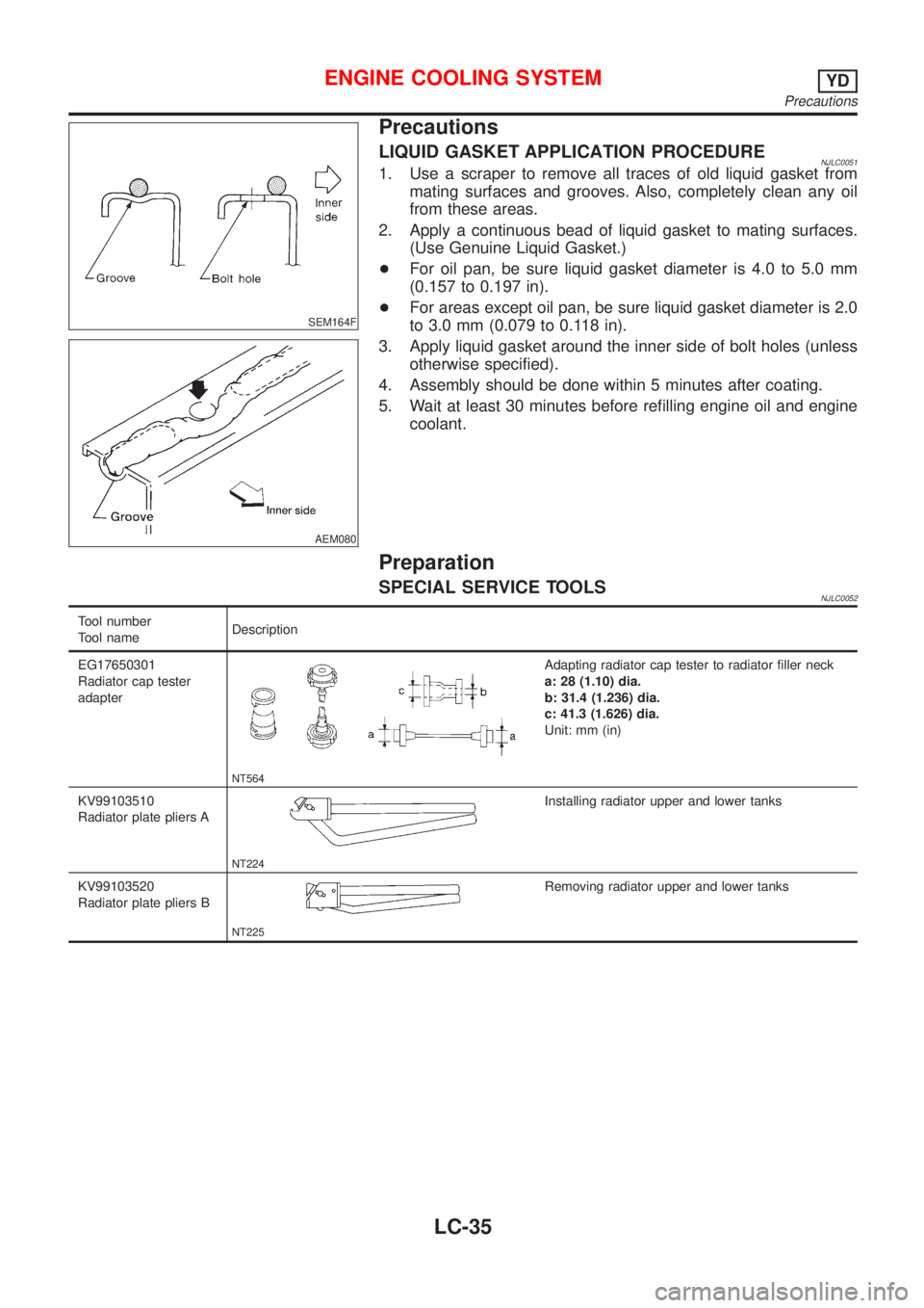
SEM164F
AEM080
Precautions
LIQUID GASKET APPLICATION PROCEDURENJLC00391. Use a scraper to remove all traces of old liquid gasket from
mating surfaces and grooves. Also, completely clean any oil
from these areas.
2. Apply a continuous bead of liquid gasket to mating surfaces.
(Use Genuine Liquid Gasket or equivalent.)
+For oil pan, be sure liquid gasket diameter is 4.0 to 5.0 mm
(0.157 to 0.197 in).
+For areas except oil pan, be sure liquid gasket diameter is 2.0
to 3.0 mm (0.079 to 0.118 in).
3. Apply liquid gasket around the inner side of bolt holes (unless
otherwise specified).
4. Assembly should be done within 5 minutes after coating.
5. Wait at least 30 minutes before refilling engine oil and engine
coolant.
Preparation
SPECIAL SERVICE TOOLSNJLC0040
Tool number
Tool nameDescription
ST25051001
Oil pressure gauge
NT050
ST25052000
Hose
NT559
Adapting oil pressure gauge to upper oil pan
WS39930000
Tube pressure
NT052
Pressing the tube of liquid gasket
ENGINE LUBRICATION SYSTEMYD
Precautions
LC-25
Page 276 of 2493
DISASSEMBLY AND ASSEMBLYNJLC0044
JLC285B
JLC286B
JLC355B
OIL PUMP INSPECTIONNJLC0045+Install the inner rotor and outer rotor with the punched
marks on the pump cover side.
Using a feeler gauge, straightedge and micrometers, check the
following clearances:
Unit: mm (in)
Body to outer rotor radial clearance10.114 - 0.260 (0.0045 - 0.0102)
Inner rotor to outer rotor tip clearance
2Below 0.18 (0.0071)
Body to inner rotor axial clearance30.050 - 0.090 (0.0020 - 0.0035)
Body to outer rotor axial clearance40.030 - 0.190 (0.0012 - 0.0075)
Inner rotor to brazed portion of hous-
ing clearance50.045 - 0.091 (0.0018 - 0.0036)
+If the tip clearance (2) exceeds the limit, replace rotor set.
+If body to rotor clearances (1, 3, 4, 5) exceed the limit,
replace oil pump body assembly.
ENGINE LUBRICATION SYSTEMYD
Oil Pump (Cont'd)
LC-28
Page 283 of 2493

SEM164F
AEM080
Precautions
LIQUID GASKET APPLICATION PROCEDURENJLC00511. Use a scraper to remove all traces of old liquid gasket from
mating surfaces and grooves. Also, completely clean any oil
from these areas.
2. Apply a continuous bead of liquid gasket to mating surfaces.
(Use Genuine Liquid Gasket.)
+For oil pan, be sure liquid gasket diameter is 4.0 to 5.0 mm
(0.157 to 0.197 in).
+For areas except oil pan, be sure liquid gasket diameter is 2.0
to 3.0 mm (0.079 to 0.118 in).
3. Apply liquid gasket around the inner side of bolt holes (unless
otherwise specified).
4. Assembly should be done within 5 minutes after coating.
5. Wait at least 30 minutes before refilling engine oil and engine
coolant.
Preparation
SPECIAL SERVICE TOOLSNJLC0052
Tool number
Tool nameDescription
EG17650301
Radiator cap tester
adapter
NT564
Adapting radiator cap tester to radiator filler neck
a: 28 (1.10) dia.
b: 31.4 (1.236) dia.
c: 41.3 (1.626) dia.
Unit: mm (in)
KV99103510
Radiator plate pliers A
NT224
Installing radiator upper and lower tanks
KV99103520
Radiator plate pliers B
NT225
Removing radiator upper and lower tanks
ENGINE COOLING SYSTEMYD
Precautions
LC-35