Page 567 of 2493
5 CHECK INTERMITTENT INCIDENT
Perform ªTROUBLE DIAGNOSIS FOR INTERMITTENT INCIDENTº, EC-144.
©INSPECTION END
SEF111Y
Component InspectionNJEC0212KNOCK SENSORNJEC0212S01+Use an ohmmeter which can measure more than 10 MW.
1. Disconnect knock sensor harness connector.
2. Check resistance between terminal 1 and ground.
Resistance: 500 - 620 kW[at 25ÉC (77ÉF)]
CAUTION:
Discard any knock sensors that have been dropped or physi-
cally damaged. Use only new ones.
DTC P0325 KNOCK SENSOR (KS)QG
Diagnostic Procedure (Cont'd)
EC-271
Page 596 of 2493

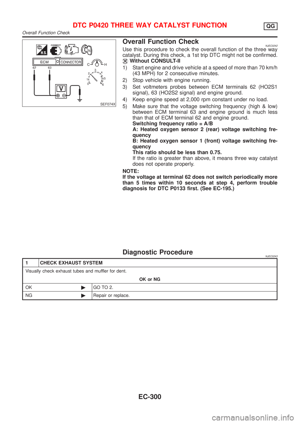
SEF074X
Overall Function CheckNJEC0242Use this procedure to check the overall function of the three way
catalyst. During this check, a 1st trip DTC might not be confirmed.
Without CONSULT-II
1) Start engine and drive vehicle at a speed of more than 70 km/h
(43 MPH) for 2 consecutive minutes.
2) Stop vehicle with engine running.
3) Set voltmeters probes between ECM terminals 62 (HO2S1
signal), 63 (HO2S2 signal) and engine ground.
4) Keep engine speed at 2,000 rpm constant under no load.
5) Make sure that the voltage switching frequency (high & low)
between ECM terminal 63 and engine ground is much less
than that of ECM terminal 62 and engine ground.
Switching frequency ratio = A/B
A: Heated oxygen sensor 2 (rear) voltage switching fre-
quency
B: Heated oxygen sensor 1 (front) voltage switching fre-
quency
This ratio should be less than 0.75.
If the ratio is greater than above, it means three way catalyst
does not operate properly.
NOTE:
If the voltage at terminal 62 does not switch periodically more
than 5 times within 10 seconds at step 4, perform trouble
diagnosis for DTC P0133 first. (See EC-195.)
Diagnostic ProcedureNJEC0243
1 CHECK EXHAUST SYSTEM
Visually check exhaust tubes and muffler for dent.
OK or NG
OK©GO TO 2.
NG©Repair or replace.
DTC P0420 THREE WAY CATALYST FUNCTIONQG
Overall Function Check
EC-300
Page 605 of 2493

SEF080X
Component DescriptionNJEC0272The vehicle speed sensor is installed in the transaxle. It contains a
pulse generator which provides a vehicle speed signal to the
speedometer. The speedometer then sends a signal to the ECM.
ECM Terminals and Reference ValueNJEC0273Specification data are reference values and are measured between each terminal and ground.
CAUTION:
Do not use ECM ground terminals when measuring input/output voltage. Doing so may result in dam-
age to the ECM's transistor. Use a ground other than ECM terminals, such as the ground.
TER-
MINAL
NO.WIRE
COLORITEM CONDITION DATA (DC Voltage)
86 PU/R Vehicle speed sensor[Engine is running]
+Lift up the vehicle
+In 2nd gear position
+Vehicle speed is 40 km/h (25 MPH)2.5-3V
SEF976W
On Board Diagnosis LogicNJEC0274
DTC No. Malfunction is detected when ... Check Items (Possible Cause)
P0500
0500+The almost 0 km/h (0 MPH) signal from vehicle speed
sensor is sent to ECM even when vehicle is being
driven.+Harness or connector
(The vehicle speed sensor circuit is open or
shorted.)
+Vehicle speed sensor
DTC Confirmation ProcedureNJEC0275CAUTION:
Always drive vehicle at a safe speed.
NOTE:
If ªDTC Confirmation Procedureº has been previously conducted,
always turn ignition switch ªOFFº and wait at least 9 seconds
before conducting the next test.
TESTING CONDITION:
This procedure may be conducted with the drive wheels lifted
in the shop or by driving the vehicle. If a road test is expected
to be easier, it is unnecessary to lift the vehicle.
DTC P0500 VEHICLE SPEED SENSOR (VSS)QG
Component Description
EC-309
Page 608 of 2493

Diagnostic ProcedureNJEC0278
1 CHECK INPUT SIGNAL CIRCUIT
1. Turn ignition switch ªOFFº.
2. Disconnect ECM harness connector and combination meter harness connector.
3. Check harness continuity between ECM terminal 86 and meter terminal 4.
Refer to wiring diagram.
Continuity should exist.
4. Also check harness for short to ground and short to power.
OK or NG
OK©GO TO 3.
NG©GO TO 2.
2 DETECT MALFUNCTIONING PART
Check the following.
+Harness connectors M63, F102
+Harness for open or short between ECM and combination meter
©Repair open circuit or short to ground or short to power in harness or connectors.
3 CHECK SPEEDOMETER FUNCTION
Make sure that speedometer functions properly.
OK or NG
OK©GO TO 5.
NG©GO TO 4.
4 CHECK SPEEDOMETER CIRCUIT
Check the following.
+Harness connectors M63, F102
+Harness connectors M169, F113
+Harness for open or short between combination meter and vehicle speed sensor
OK©Check combination meter and vehicle speed sensor. Refer to EL-89, ªMETERS AND
GAUGESº.
NG©Repair open circuit or short to ground or short to power in harness or connectors.
5 CHECK INTERMITTENT INCIDENT
Perform ªTROUBLE DIAGNOSIS FOR INTERMITTENT INCIDENTº, EC-144.
©INSPECTION END
DTC P0500 VEHICLE SPEED SENSOR (VSS)QG
Diagnostic Procedure
EC-312
Page 671 of 2493

Diagnostic ProcedureNJEC1221
1 INSPECTION START
Do you have CONSULT-II?
YesorNo
Ye s©GO TO 2.
No©GO TO 3.
2 CHECK OVERALL FUNCTION
With CONSULT-II
1. Start engine and warm it up to normal operating temperature.
2. Select ªHO2S1 MNTR (B1)º in ªDATA MONITORº mode with CONSULT-II.
3. Keep the engine speed at 2,000 rpm under no load, and make sure that the monitors fluctuate between LEAN and
RICH more than five times in 10 seconds.
SEF218Z
OK or NG
OK©INSPECTION END
NG©GO TO 4.
3 CHECK OVERALL FUNCTION
Without CONSULT-II
1. Start engine and warm it up to normal operating temperature.
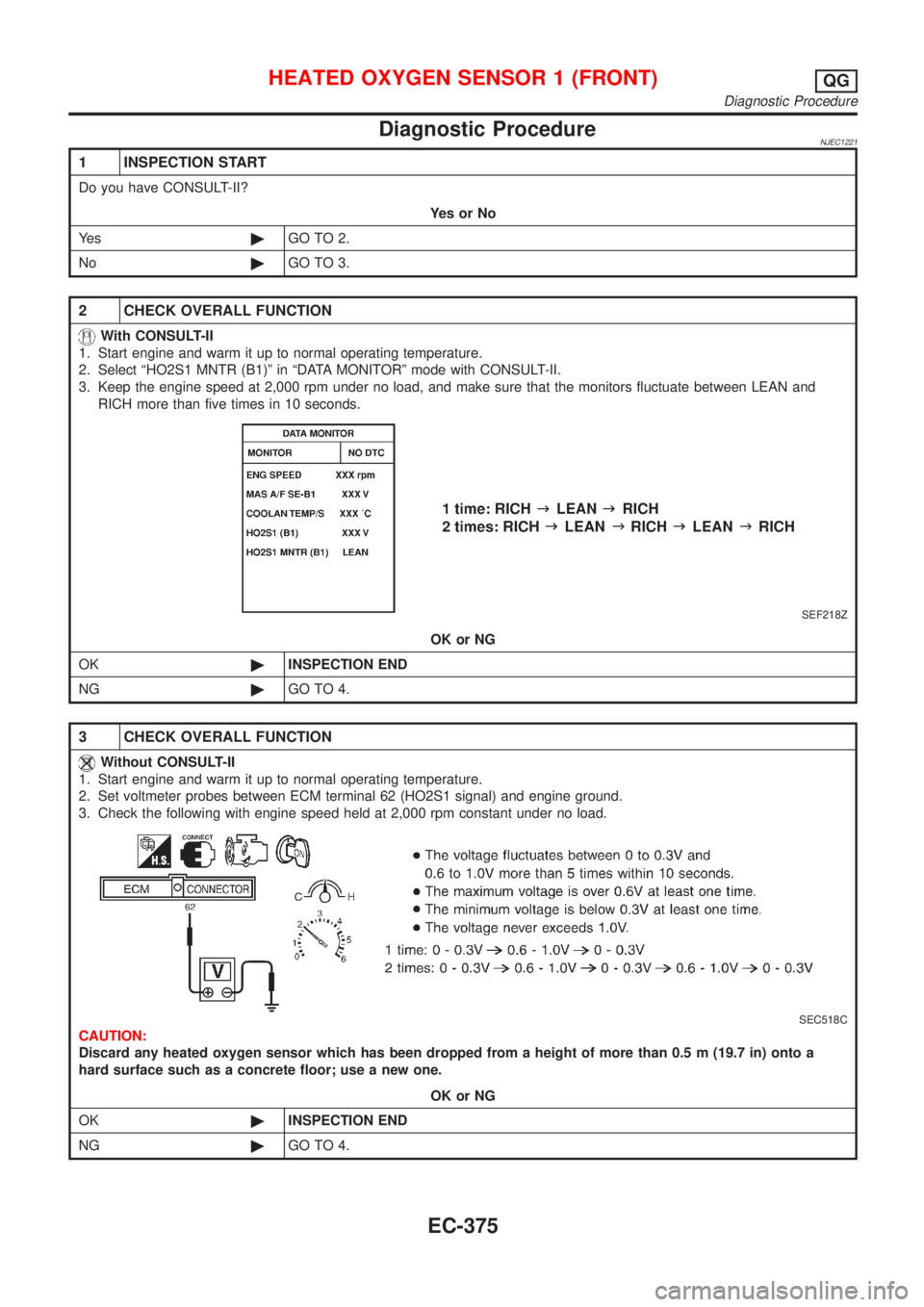
2. Set voltmeter probes between ECM terminal 62 (HO2S1 signal) and engine ground.
3. Check the following with engine speed held at 2,000 rpm constant under no load.
SEC518C
CAUTION:
Discard any heated oxygen sensor which has been dropped from a height of more than 0.5 m (19.7 in) onto a
hard surface such as a concrete floor; use a new one.
OK or NG
OK©INSPECTION END
NG©GO TO 4.
HEATED OXYGEN SENSOR 1 (FRONT)QG
Diagnostic Procedure
EC-375
Page 674 of 2493
SEF648Y
SEF011X
Without CONSULT-II
1) Start engine and warm it up to normal operating temperature.
2) Set voltmeter probes between ECM terminal 62 (HO2S1 sig-
nal) and engine ground.
3) Check the following with engine speed held at 2,000 rpm con-
stant under no load.
+The voltage fluctuates between 0 to 0.3V and 0.6 to 1.0V more
than 5 times within 10 seconds.
+The maximum voltage is over 0.6V at least one time.
+The minimum voltage is below 0.3V at least one time.
+The voltage never exceeds 1.0V.
1 time: 0 - 0.3V®0.6 - 1.0V®0 - 0.3V
2 times: 0 - 0.3V®0.6 - 1.0V®0 - 0.3V®0.6 - 1.0V®0-
0.3V
CAUTION:
+Discard any heated oxygen sensor which has been
dropped from a height of more than 0.5 m (19.7 in) onto a
hard surface such as a concrete floor; use a new one.
+Before installing new oxygen sensor, clean exhaust sys-
tem threads using Oxygen Sensor Thread Cleaner tool
and approved anti-seize lubricant.
HEATED OXYGEN SENSOR 1 (FRONT)QG
Component Inspection (Cont'd)
EC-378
Page 681 of 2493
Diagnostic ProcedureNJEC1238
1 CHECK OVERALL FUNCTION-I
1. Start engine and drive the vehicle at over 70 km/h (43 MPH) for 2 consecutive minutes.
2. Stop vehicle and keep the engine running.
3. Set voltmeter probes between ECM terminals 63 [HO2S2 (B1) signal] and ground.
4. Check the voltage while revving up to 4,000 rpm under no load at least 10 times.
(Depress and release the accelerator pedal as quickly as possible.)
SEF240Z
OK or NG
OK©INSPECTION END
NG©GO TO 2.
2 CHECK OVERALL FUNCTION-II
Keep engine at idle for 10 minutes, then check the voltage between ECM terminal 63 and ground, or check the voltage
when coasting at 80 km/h (50 MPH) in 3rd gear (M/T), ªDº position with ªODº OFF (A/T).
SEF240Z
OK or NG
OK©INSPECTION END
NG©GO TO 3.
HEATED OXYGEN SENSOR 2 (REAR)QG
Diagnostic Procedure
EC-385
Page 684 of 2493

SEF032X
Without CONSULT-II
1) Start engine and drive vehicle at a speed of more than 70 km/h
(43 MPH) for 2 consecutive minutes.
2) Stop vehicle with engine running.
3) Set voltmeter probes between ECM terminals 63 (HO2S2 sig-
nal) and engine ground.
4) Check the voltage when revving up to 4,000 rpm under no load
at least 10 times.
(Depress and release accelerator pedal as soon as possible.)
The voltage should be above 0.68V at least once.
If the voltage is above 0.68V at step 4, step 5 is not nec-
essary.
5) Check the voltage when revving up to 6,000 rpm under no
load. Or keep vehicle at idling for 10 minutes, then check the
voltage. Or check the voltage when coasting from 80 km/h (50
MPH) in 3rd gear position (M/T), D position with ªODº OFF
(A/T).
The voltage should be below 0.56V at least once.
CAUTION:
+Discard any heated oxygen sensor which has been
dropped from a height of more than 0.5 m (19.7 in) onto a
hard surface such as a concrete floor; use a new one.
+Before installing new oxygen sensor, clean exhaust sys-
tem threads using Oxygen Sensor Thread Cleaner tool
and approved anti-seize lubricant.
HEATED OXYGEN SENSOR 2 (REAR)QG
Component Inspection (Cont'd)
EC-388