2001 NISSAN ALMERA N16 speedometer
[x] Cancel search: speedometerPage 424 of 2493

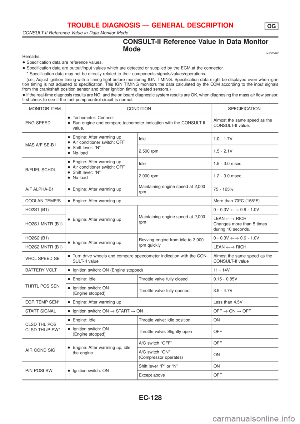
CONSULT-II Reference Value in Data Monitor
Mode
NJEC0042Remarks:
+Specification data are reference values.
+Specification data are output/input values which are detected or supplied by the ECM at the connector.
* Specification data may not be directly related to their components signals/values/operations.
(i.e., Adjust ignition timing with a timing light before monitoring IGN TIMING. Specification data might be displayed even when igni-
tion timing is not adjusted to specification. This IGN TIMING monitors the data calculated by the ECM according to the input signals
from the crankshaft position sensor and other ignition timing related sensors.)
+If the real-time diagnosis results are NG, and the on board diagnostic system results are OK, when diagnosing the mass air flow sensor,
first check to see if the fuel pump control circuit is normal.
MONITOR ITEM CONDITION SPECIFICATION
ENG SPEED+Tachometer: Connect
+Run engine and compare tachometer indication with the CONSULT-II
value.Almost the same speed as the
CONSULT-II value.
MAS A/F SE-B1+Engine: After warming up
+Air conditioner switch: OFF
+Shift lever: ªNº
+No-loadIdle 1.0 - 1.7V
2,500 rpm 1.5 - 2.1V
B/FUEL SCHDL+Engine: After warming up
+Air conditioner switch: OFF
+Shift lever: ªNº
+No-loadIdle 1.5 - 3.0 msec
2,000 rpm 1.2 - 3.0 msec
A/F ALPHA-B1+Engine: After warming upMaintaining engine speed at 2,000
rpm75 - 125%
COOLAN TEMP/S+Engine: After warming up More than 70ÉC (158ÉF)
HO2S1 (B1)
+Engine: After warming upMaintaining engine speed at 2,000
rpm0 - 0.3V¨0.6 - 1.0V
HO2S1 MNTR (B1)LEAN¨RICH
Changes more than 5 times
during 10 seconds.
HO2S2 (B1)
+Engine: After warming upRevving engine from idle to 3,000
rpm quickly0 - 0.3V¨0.6 - 1.0V
HO2S2 MNTR (B1)LEAN¨RICH
VHCL SPEED SE+Turn drive wheels and compare speedometer indication with the CON-
SULT-II valueAlmost the same speed as the
CONSULT-II value
BATTERY VOLT+Ignition switch: ON (Engine stopped) 11 - 14V
THRTL POS SEN+Engine: Idle Throttle valve fully closed 0.15 - 0.85V
+Ignition switch: ON
(Engine stopped)Throttle valve fully opened 3.5 - 4.7V
EGR TEMP SEN*+Engine: After warming up Less than 4.5V
START SIGNAL+Ignition switch: ON®START®ON OFF®ON®OFF
CLSD THL POS
CLSD THL/P SW*+Engine: Idle Throttle valve: Idle position ON
+Ignition switch: ON
(Engine stopped)Throttle valve: Slightly open OFF
AIR COND SIG+Engine: After warming up, idle
the engineA/C switch ªOFFº OFF
A/C switch ªONº
(Compressor operates)ON
P/N POSI SW+Ignition switch: ONShift lever ªPº or ªNº ON
Except above OFF
TROUBLE DIAGNOSIS Ð GENERAL DESCRIPTIONQG
CONSULT-II Reference Value in Data Monitor Mode
EC-128
Page 605 of 2493

SEF080X
Component DescriptionNJEC0272The vehicle speed sensor is installed in the transaxle. It contains a
pulse generator which provides a vehicle speed signal to the
speedometer. The speedometer then sends a signal to the ECM.
ECM Terminals and Reference ValueNJEC0273Specification data are reference values and are measured between each terminal and ground.
CAUTION:
Do not use ECM ground terminals when measuring input/output voltage. Doing so may result in dam-
age to the ECM's transistor. Use a ground other than ECM terminals, such as the ground.
TER-
MINAL
NO.WIRE
COLORITEM CONDITION DATA (DC Voltage)
86 PU/R Vehicle speed sensor[Engine is running]
+Lift up the vehicle
+In 2nd gear position
+Vehicle speed is 40 km/h (25 MPH)2.5-3V
SEF976W
On Board Diagnosis LogicNJEC0274
DTC No. Malfunction is detected when ... Check Items (Possible Cause)
P0500
0500+The almost 0 km/h (0 MPH) signal from vehicle speed
sensor is sent to ECM even when vehicle is being
driven.+Harness or connector
(The vehicle speed sensor circuit is open or
shorted.)
+Vehicle speed sensor
DTC Confirmation ProcedureNJEC0275CAUTION:
Always drive vehicle at a safe speed.
NOTE:
If ªDTC Confirmation Procedureº has been previously conducted,
always turn ignition switch ªOFFº and wait at least 9 seconds
before conducting the next test.
TESTING CONDITION:
This procedure may be conducted with the drive wheels lifted
in the shop or by driving the vehicle. If a road test is expected
to be easier, it is unnecessary to lift the vehicle.
DTC P0500 VEHICLE SPEED SENSOR (VSS)QG
Component Description
EC-309
Page 608 of 2493

Diagnostic ProcedureNJEC0278
1 CHECK INPUT SIGNAL CIRCUIT
1. Turn ignition switch ªOFFº.
2. Disconnect ECM harness connector and combination meter harness connector.
3. Check harness continuity between ECM terminal 86 and meter terminal 4.
Refer to wiring diagram.
Continuity should exist.
4. Also check harness for short to ground and short to power.
OK or NG
OK©GO TO 3.
NG©GO TO 2.
2 DETECT MALFUNCTIONING PART
Check the following.
+Harness connectors M63, F102
+Harness for open or short between ECM and combination meter
©Repair open circuit or short to ground or short to power in harness or connectors.
3 CHECK SPEEDOMETER FUNCTION
Make sure that speedometer functions properly.
OK or NG
OK©GO TO 5.
NG©GO TO 4.
4 CHECK SPEEDOMETER CIRCUIT
Check the following.
+Harness connectors M63, F102
+Harness connectors M169, F113
+Harness for open or short between combination meter and vehicle speed sensor
OK©Check combination meter and vehicle speed sensor. Refer to EL-89, ªMETERS AND
GAUGESº.
NG©Repair open circuit or short to ground or short to power in harness or connectors.
5 CHECK INTERMITTENT INCIDENT
Perform ªTROUBLE DIAGNOSIS FOR INTERMITTENT INCIDENTº, EC-144.
©INSPECTION END
DTC P0500 VEHICLE SPEED SENSOR (VSS)QG
Diagnostic Procedure
EC-312
Page 847 of 2493

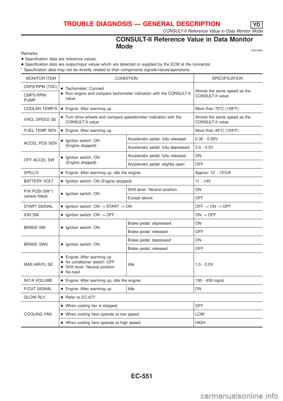
CONSULT-II Reference Value in Data Monitor
Mode
NJEC0634Remarks:
+Specification data are reference values.
+Specification data are output/input values which are detected or supplied by the ECM at the connector.
* Specification data may not be directly related to their components signals/values/operations.
MONITOR ITEM CONDITION SPECIFICATION
CKPS´RPM (TDC)
+Tachometer: Connect
+Run engine and compare tachometer indication with the CONSULT-II
value.Almost the same speed as the
CONSULT-II value. CMPS´RPM-
PUMP
COOLAN TEMP/S+Engine: After warming up More than 70ÉC (158ÉF)
VHCL SPEED SE+Turn drive wheels and compare speedometer indication with the
CONSULT-II valueAlmost the same speed as the
CONSULT-II value
FUEL TEMP SEN+Engine: After warming up More than 40ÉC (104ÉF)
ACCEL POS SEN+Ignition switch: ON
(Engine stopped)Accelerator pedal: fully released 0.30 - 0.50V
Accelerator pedal: fully depressed 3.0 - 4.3V
OFF ACCEL SW+Ignition switch: ON
(Engine stopped)Accelerator pedal: fully released ON
Accelerator pedal: slightly open OFF
SPILL/V+Engine: After warming up, idle the engine. Approx. 12 - 13ÉCA
BATTERY VOLT+Ignition switch: ON (Engine stopped) 11 - 14V
P/N POSI SW*1
(where fitted)+Ignition switch: ONShift lever: Neutral position ON
Except above OFF
START SIGNAL+Ignition switch: ON®START®ON OFF®ON®OFF
IGN SW+Ignition switch: ON®OFF ON®OFF
BRAKE SW+Ignition switch: ONBrake pedal: depressed ON
Brake pedal: released OFF
BRAKE SW2+Ignition switch: ONBrake pedal: depressed ON
Brake pedal: released OFF
MAS AIR/FL SE+Engine: After warming up
+Air conditioner switch: OFF
+Shift lever: Neutral position
+No-loadIdle 1.5 - 2.0V
INT/A VOLUME+Engine: After warming up, idle the engine. 150 - 450 mg/st
F/CUT SIGNAL+Engine: After warming up Idle ON
GLOW RLY+Refer to EC-677.
COOLING FAN+When cooling fan is stopped. OFF
+When cooling fans operate at low speed. LOW
+When cooling fans operate at high speed. HIGH
TROUBLE DIAGNOSIS Ð GENERAL DESCRIPTIONYD
CONSULT-II Reference Value in Data Monitor Mode
EC-551
Page 889 of 2493

AEC110
DescriptionNJEC0654The vehicle speed sensor is installed in the transaxle. It contains a
pulse generator which provides a vehicle speed signal to the
speedometer. The speedometer then sends a signal to the ECM.
ECM Terminals and Reference ValueNJEC0655Specification data are reference values and are measured between each terminal and ground.
CAUTION:
Do not use ECM ground terminals when measuring input/output voltage. Doing so may result in dam-
age to the ECM's transistor. Use a ground other than ECM terminals, such as the ground.
TER-
MINAL
NO.WIRE
COLORITEM CONDITIONDATA (DC Voltage and
Pulse Signal)
417 PU/R Vehicle speed sensor[Engine is running]
+Lift up the vehicle.
+In 1st gear position
+Vehicle speed is 10 km/h (6 MPH)Approximately 8V
SEF891Y
[Engine is running]
+Lift up the vehicle.
+In 2nd gear position
+Vehicle speed is 30 km/h (19 MPH)Approximately 6V
SEF892Y
On Board Diagnosis LogicNJEC0656
DTC Malfunction is detected when .... Check Items (Possible Cause)
P0500
0104+The almost 0 km/h (0 MPH) signal from vehicle
speed sensor is sent to ECM even when vehicle
is being driven.+Harness or connector
(The vehicle speed sensor circuit is open or
shorted.)
+Vehicle speed sensor
SEF864Y
Overall Function CheckNJEC0657Use this procedure to check the overall function of the vehicle
speed sensor circuit. During this check, a DTC might not be con-
firmed.
WITH CONSULT-IINJEC0657S011) Lift up the vehicle.
2) Start engine.
3) Read vehicle speed sensor signal in ªDATA MONITORº mode
with CONSULT-II.
The vehicle speed on CONSULT-II should be able to
DTC P0500 VEHICLE SPEED SENYD
Description
EC-593
Page 892 of 2493

Diagnostic ProcedureNJEC0659
1 CHECK VEHICLE SPEED SENSOR INPUT SIGNAL CIRCUIT FOR OPEN AND SHORT
1. Turn ignition switch ªOFFº.
2. Disconnect ECM harness connector and combination meter harness connector.
3. Check harness continuity between ECM terminal 417 and combination meter terminal 4. Refer to Wiring Diagram.
Continuity should exist.
4. Also check harness for short to ground and short to power.
OK or NG
OK©GO TO 3.
NG©GO TO 2.
2 DETECT MALFUNCTIONING PART
Check the following.
+Harness connectors M63, F102
+Harness for open or short between ECM and combination meter
©Repair open circuit or short to ground or short to power in harness or connectors.
3 CHECK SPEEDOMETER FUNCTION
Make sure that speedometer functions properly.
OK or NG
OK©GO TO 5.
NG©GO TO 4.
4 CHECK SPEEDOMETER CIRCUIT FOR OPEN AND SHORT
Check the following.
+Harness connectors M63, F102
+Harness for open or short between vehicle speed sensor and engine ground
+Harness for open or short between combination meter and vehicle speed sensor
OK or NG
OK©Check vehicle speed sensor and combination meter. Refer to EL section.
NG©Repair open circuit or short to ground or short to power in harness or connectors.
5 CHECK INTERMITTENT INCIDENT
Refer to ªTROUBLE DIAGNOSIS FOR INTERMITTENT INCIDENTº, EC-559.
©INSPECTION END
DTC P0500 VEHICLE SPEED SENYD
Diagnostic Procedure
EC-596
Page 1073 of 2493

NJMT0008
SMT928D
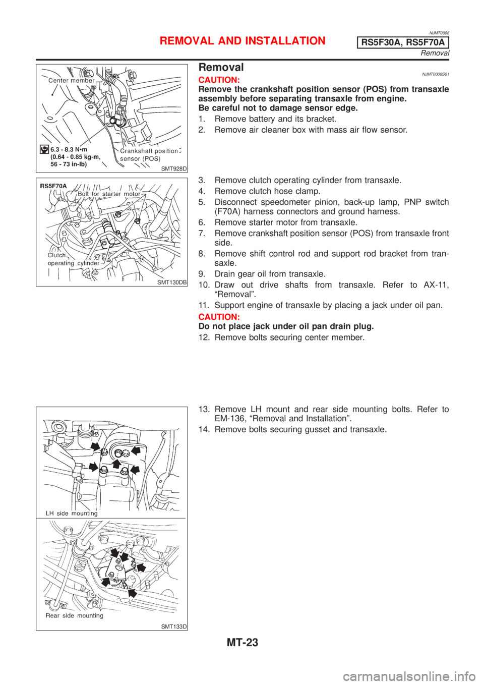
RemovalNJMT0008S01CAUTION:
Remove the crankshaft position sensor (POS) from transaxle
assembly before separating transaxle from engine.
Be careful not to damage sensor edge.
1. Remove battery and its bracket.
2. Remove air cleaner box with mass air flow sensor.
SMT130DB
3. Remove clutch operating cylinder from transaxle.
4. Remove clutch hose clamp.
5. Disconnect speedometer pinion, back-up lamp, PNP switch
(F70A) harness connectors and ground harness.
6. Remove starter motor from transaxle.
7. Remove crankshaft position sensor (POS) from transaxle front
side.
8. Remove shift control rod and support rod bracket from tran-
saxle.
9. Drain gear oil from transaxle.
10. Draw out drive shafts from transaxle. Refer to AX-11,
ªRemovalº.
11. Support engine of transaxle by placing a jack under oil pan.
CAUTION:
Do not place jack under oil pan drain plug.
12. Remove bolts securing center member.
SMT133D
13. Remove LH mount and rear side mounting bolts. Refer to
EM-136, ªRemoval and Installationº.
14. Remove bolts securing gusset and transaxle.
REMOVAL AND INSTALLATIONRS5F30A, RS5F70A
Removal
MT-23
Page 1076 of 2493

NJMT0090
SMT928D
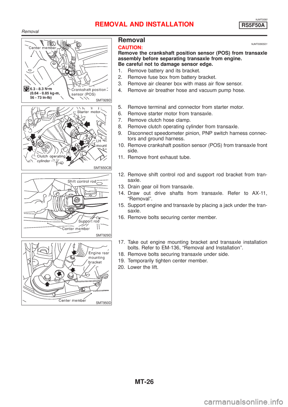
RemovalNJMT0090S01CAUTION:
Remove the crankshaft position sensor (POS) from transaxle
assembly before separating transaxle from engine.
Be careful not to damage sensor edge.
1. Remove battery and its bracket.
2. Remove fuse box from battery bracket.
3. Remove air cleaner box with mass air flow sensor.
4. Remove air breather hose and vacuum pump hose.
SMT650CB
5. Remove terminal and connector from starter motor.
6. Remove starter motor from transaxle.
7. Remove clutch hose clamp.
8. Remove clutch operating cylinder from transaxle.
9. Disconnect speedometer pinion, PNP switch harness connec-
tors and ground harness.
10. Remove crankshaft position sensor (POS) from transaxle front
side.
11. Remove front exhaust tube.
SMT929D
12. Remove shift control rod and support rod bracket from tran-
saxle.
13. Drain gear oil from transaxle.
14. Draw out drive shafts from transaxle. Refer to AX-11,
ªRemovalº.
15. Support engine and transaxle by placing a jack under the tran-
saxle.
16. Remove bolts securing center member.
SMT950D
17. Take out engine mounting bracket and transaxle installation
bolts. Refer to EM-136, ªRemoval and Installationº.
18. Remove bolts securing transaxle under side.
19. Temporarily tighten center member.
20. Lower the lift.
REMOVAL AND INSTALLATIONRS5F50A
Removal
MT-26