2001 NISSAN ALMERA N16 Meter
[x] Cancel search: MeterPage 1157 of 2493
SMT059A
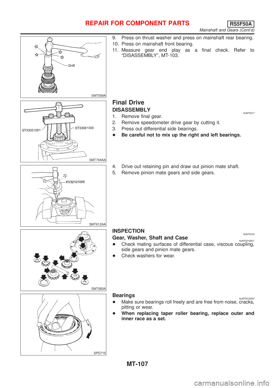
9. Press on thrust washer and press on mainshaft rear bearing.
10. Press on mainshaft front bearing.
11. Measure gear end play as a final check. Refer to
ªDISASSEMBLYº, MT-103.
SMT744AA
Final Drive
DISASSEMBLYNJMT00171. Remove final gear.
2. Remove speedometer drive gear by cutting it.
3. Press out differential side bearings.
+Be careful not to mix up the right and left bearings.
SMT612AA
4. Drive out retaining pin and draw out pinion mate shaft.
5. Remove pinion mate gears and side gears.
SMT083A
INSPECTIONNJMT0018Gear, Washer, Shaft and CaseNJMT0018S01+Check mating surfaces of differential case, viscous coupling,
side gears and pinion mate gears.
+Check washers for wear.
SPD715
BearingsNJMT0018S03+Make sure bearings roll freely and are free from noise, cracks,
pitting or wear.
+When replacing taper roller bearing, replace outer and
inner race as a set.
REPAIR FOR COMPONENT PARTSRS5F50A
Mainshaft and Gears (Cont'd)
MT-107
Page 1159 of 2493
SMT609A
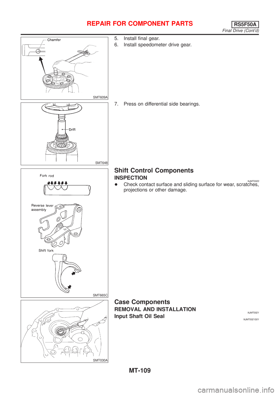
5. Install final gear.
6. Install speedometer drive gear.
SMT648
7. Press on differential side bearings.
SMT665C
Shift Control Components
INSPECTIONNJMT0020+Check contact surface and sliding surface for wear, scratches,
projections or other damage.
SMT030A
Case Components
REMOVAL AND INSTALLATIONNJMT0021Input Shaft Oil SealNJMT0021S01
REPAIR FOR COMPONENT PARTSRS5F50A
Final Drive (Cont'd)
MT-109
Page 1161 of 2493
NJMT0022
Input Shaft End Play and Differential Side
Bearing Preload
NJMT0022S01If any of the following parts are replaced, adjust input shaft end
play.
+Input shaft
+Input shaft bearing
+Clutch housing
+Transmission case
If any of the following parts are replaced, adjust differential side
bearing preload.
+Differential case
+Differential side bearing
+Clutch housing
+Transmission case
SMT132AA
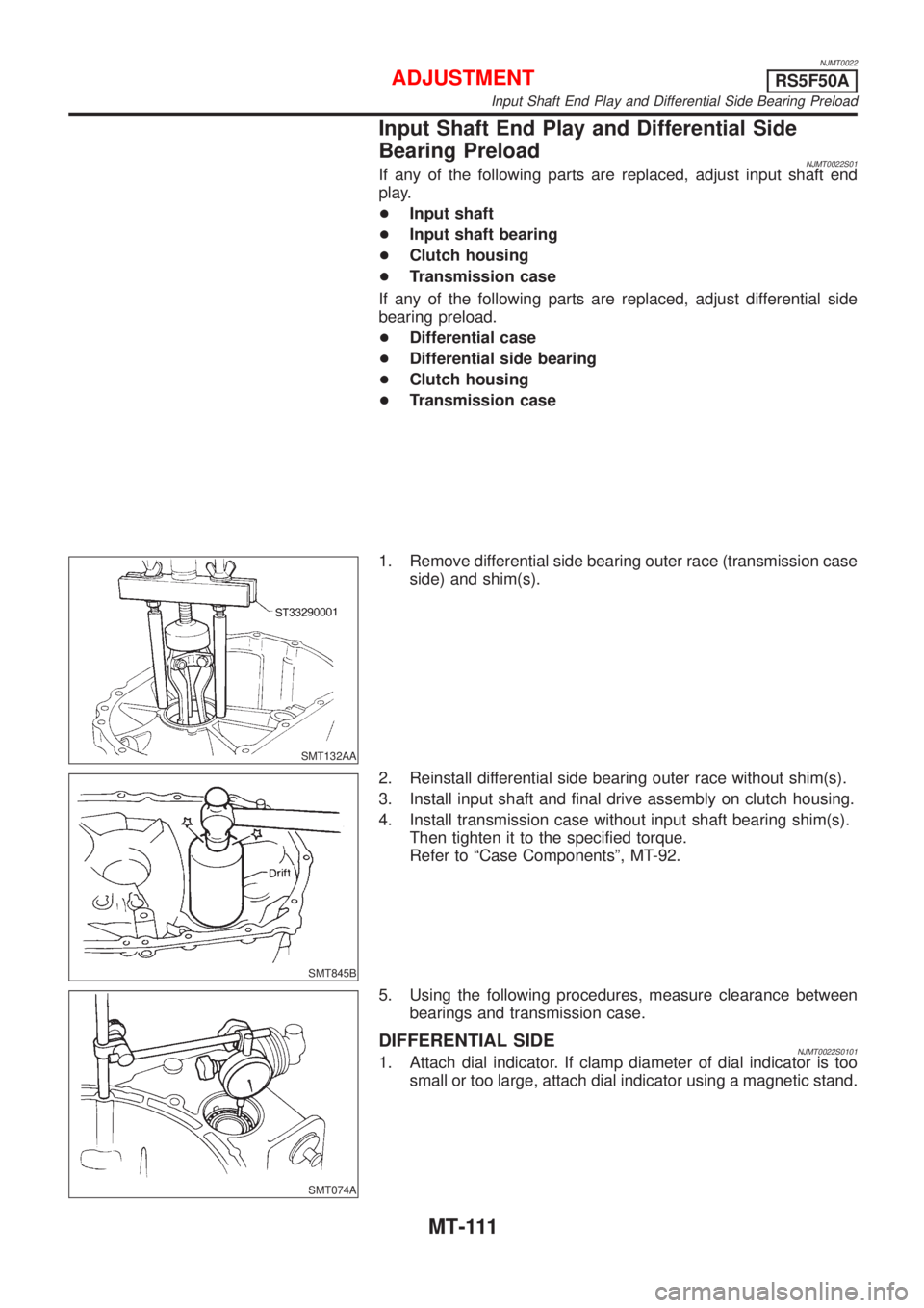
1. Remove differential side bearing outer race (transmission case
side) and shim(s).
SMT845B
2. Reinstall differential side bearing outer race without shim(s).
3. Install input shaft and final drive assembly on clutch housing.
4. Install transmission case without input shaft bearing shim(s).
Then tighten it to the specified torque.
Refer to ªCase Componentsº, MT-92.
SMT074A
5. Using the following procedures, measure clearance between
bearings and transmission case.
DIFFERENTIAL SIDENJMT0022S01011. Attach dial indicator. If clamp diameter of dial indicator is too
small or too large, attach dial indicator using a magnetic stand.
ADJUSTMENTRS5F50A
Input Shaft End Play and Differential Side Bearing Preload
MT-111
Page 1163 of 2493
SMT644AA
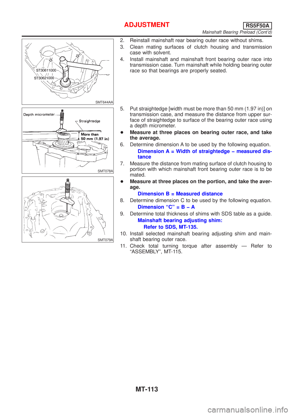
2. Reinstall mainshaft rear bearing outer race without shims.
3. Clean mating surfaces of clutch housing and transmission
case with solvent.
4. Install mainshaft and mainshaft front bearing outer race into
transmission case. Turn mainshaft while holding bearing outer
race so that bearings are properly seated.
SMT078A
SMT079A
5. Put straightedge [width must be more than 50 mm (1.97 in)] on
transmission case, and measure the distance from upper sur-
face of straightedge to surface of the bearing outer race using
a depth micrometer.
+Measure at three places on bearing outer race, and take
the average.
6. Determine dimension A to be used by the following equation.
Dimension A = Width of straightedge þ measured dis-
tance
7. Measure the distance from mating surface of clutch housing to
portion with which mainshaft front bearing outer race is to be
mated.
+Measure at three places on the portion, and take the aver-
age.
Dimension B = Measured distance
8. Determine dimension C to be used by the following equation.
Dimension ªCº=BþA
9. Determine total thickness of shims with SDS table as a guide.
Mainshaft bearing adjusting shim:
Refer to SDS, MT-135.
10. Install selected mainshaft bearing adjusting shim and main-
shaft bearing outer race.
11. Check total turning torque after assembly Ð Refer to
ªASSEMBLYº, MT-115.
ADJUSTMENTRS5F50A
Mainshaft Bearing Preload (Cont'd)
MT-113
Page 1224 of 2493
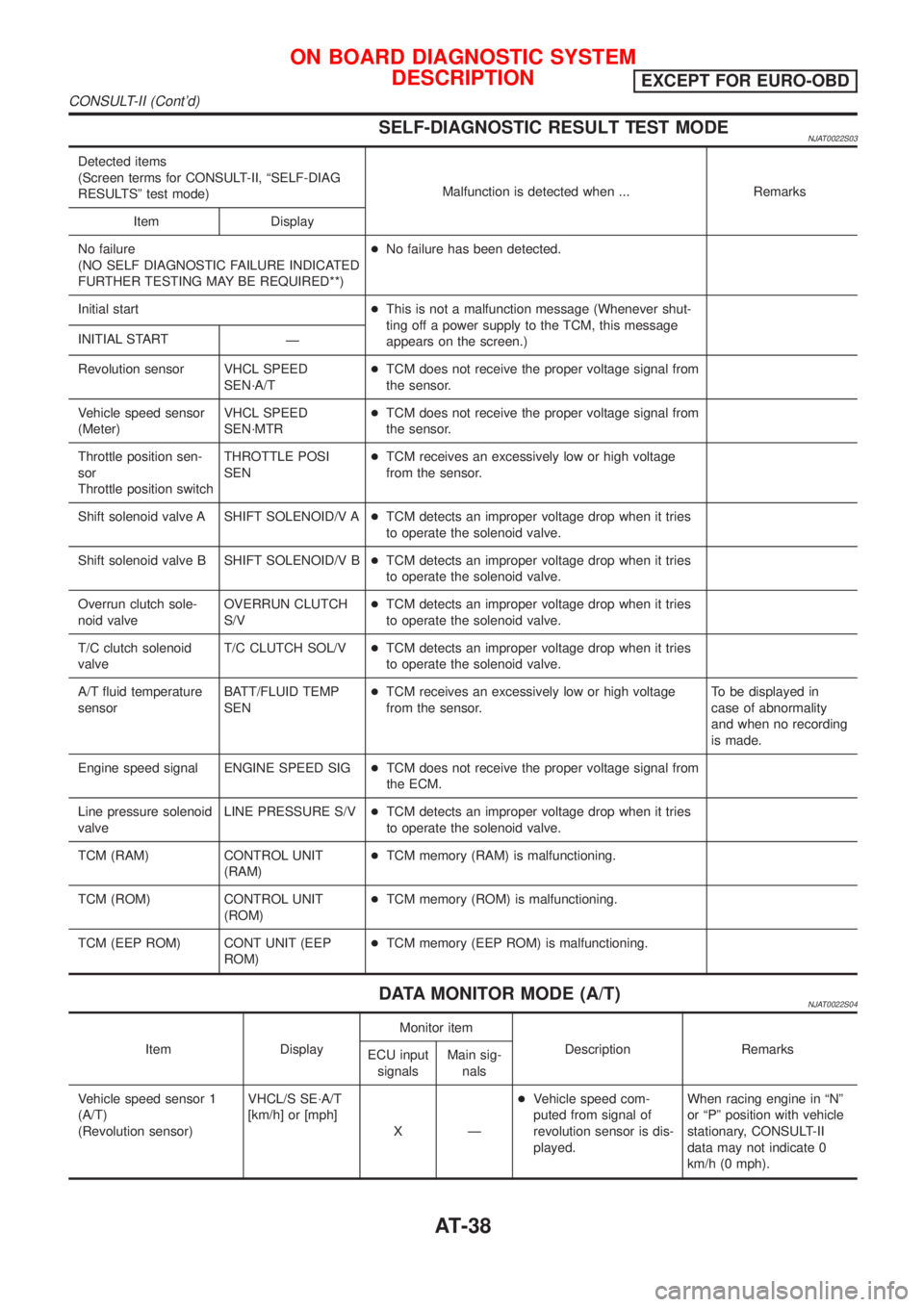
SELF-DIAGNOSTIC RESULT TEST MODENJAT0022S03
Detected items
(Screen terms for CONSULT-II, ªSELF-DIAG
RESULTSº test mode)Malfunction is detected when ... Remarks
Item Display
No failure
(NO SELF DIAGNOSTIC FAILURE INDICATED
FURTHER TESTING MAY BE REQUIRED**)+No failure has been detected.
Initial start+This is not a malfunction message (Whenever shut-
ting off a power supply to the TCM, this message
appears on the screen.) INITIAL START
Ð
Revolution sensor VHCL SPEED
SEN´A/T+TCM does not receive the proper voltage signal from
the sensor.
Vehicle speed sensor
(Meter)VHCL SPEED
SEN´MTR+TCM does not receive the proper voltage signal from
the sensor.
Throttle position sen-
sor
Throttle position switchTHROTTLE POSI
SEN+TCM receives an excessively low or high voltage
from the sensor.
Shift solenoid valve A SHIFT SOLENOID/V A+TCM detects an improper voltage drop when it tries
to operate the solenoid valve.
Shift solenoid valve B SHIFT SOLENOID/V B+TCM detects an improper voltage drop when it tries
to operate the solenoid valve.
Overrun clutch sole-
noid valveOVERRUN CLUTCH
S/V+TCM detects an improper voltage drop when it tries
to operate the solenoid valve.
T/C clutch solenoid
valveT/C CLUTCH SOL/V+TCM detects an improper voltage drop when it tries
to operate the solenoid valve.
A/T fluid temperature
sensorBATT/FLUID TEMP
SEN+TCM receives an excessively low or high voltage
from the sensor.To be displayed in
case of abnormality
and when no recording
is made.
Engine speed signal ENGINE SPEED SIG+TCM does not receive the proper voltage signal from
the ECM.
Line pressure solenoid
valveLINE PRESSURE S/V+TCM detects an improper voltage drop when it tries
to operate the solenoid valve.
TCM (RAM) CONTROL UNIT
(RAM)+TCM memory (RAM) is malfunctioning.
TCM (ROM) CONTROL UNIT
(ROM)+TCM memory (ROM) is malfunctioning.
TCM (EEP ROM) CONT UNIT (EEP
ROM)+TCM memory (EEP ROM) is malfunctioning.
DATA MONITOR MODE (A/T)NJAT0022S04
Item DisplayMonitor item
Description Remarks
ECU input
signalsMain sig-
nals
Vehicle speed sensor 1
(A/T)
(Revolution sensor)VHCL/S SE´A/T
[km/h] or [mph]
XÐ+Vehicle speed com-
puted from signal of
revolution sensor is dis-
played.When racing engine in ªNº
or ªPº position with vehicle
stationary, CONSULT-II
data may not indicate 0
km/h (0 mph).
ON BOARD DIAGNOSTIC SYSTEM
DESCRIPTION
EXCEPT FOR EURO-OBD
CONSULT-II (Cont'd)
AT-38
Page 1225 of 2493
![NISSAN ALMERA N16 2001 Electronic Repair Manual Item DisplayMonitor item
Description Remarks
ECU input
signalsMain sig-
nals
Vehicle speed sensor 2
(Meter)VHCL/S SE´MTR
[km/h] or [mph]
XÐ+Vehicle speed com-
puted from signal of
vehicle speed sens NISSAN ALMERA N16 2001 Electronic Repair Manual Item DisplayMonitor item
Description Remarks
ECU input
signalsMain sig-
nals
Vehicle speed sensor 2
(Meter)VHCL/S SE´MTR
[km/h] or [mph]
XÐ+Vehicle speed com-
puted from signal of
vehicle speed sens](/manual-img/5/57351/w960_57351-1224.png)
Item DisplayMonitor item
Description Remarks
ECU input
signalsMain sig-
nals
Vehicle speed sensor 2
(Meter)VHCL/S SE´MTR
[km/h] or [mph]
XÐ+Vehicle speed com-
puted from signal of
vehicle speed sensor is
displayed.Vehicle speed display may
not be accurate under
approx. 10 km/h (6 mph).
It may not indicate 0 km/h
(0 mph) when vehicle is
stationary.
Throttle position sensor THRTL POS SEN
[V] X Ð+Throttle position sensor
signal voltage is dis-
played.
A/T fluid temperature sen-
sorFLUID TEMP SE
[V]
XÐ+A/T fluid temperature
sensor signal voltage is
displayed.
+Signal voltage lowers as
fluid temperature rises.
Battery voltage BATTERY VOLT
[V]XÐ+Source voltage of TCM
is displayed.
Engine speed ENGINE SPEED
[rpm]
XX+Engine speed, com-
puted from engine
speed signal, is dis-
played.Engine speed display may
not be accurate under
approx. 800 rpm. It may
not indicate 0 rpm even
when engine is not run-
ning.
Overdrive control switch OVERDRIVE SW
[ON/OFF]
XÐ+ON/OFF state com-
puted from signal of
overdrive control SW is
displayed.
P/N position switch PN POSI SW
[ON/OFF]
XÐ+ON/OFF state com-
puted from signal of P/N
position SW is dis-
played.
R position switch R POSITION SW
[ON/OFF]
XÐ+ON/OFF state com-
puted from signal of R
position SW is dis-
played.
D position switch D POSITION SW
[ON/OFF]
XÐ+ON/OFF state com-
puted from signal of D
position SW is dis-
played.
2 position switch 2 POSITION SW
[ON/OFF]
XÐ+ON/OFF status, com-
puted from signal of 2
position SW, is dis-
played.
1 position switch 1 POSITION SW
[ON/OFF]
XÐ+ON/OFF status, com-
puted from signal of 1
position SW, is dis-
played.
ASCD cruise signal ASCD-CRUISE
[ON/OFF]
XÐ+Status of ASCD cruise
signal is displayed.
ON ... Cruising state
OFF ... Normal running
state+This is displayed even
when no ASCD is
mounted.
ON BOARD DIAGNOSTIC SYSTEM
DESCRIPTION
EXCEPT FOR EURO-OBD
CONSULT-II (Cont'd)
AT-39
Page 1239 of 2493
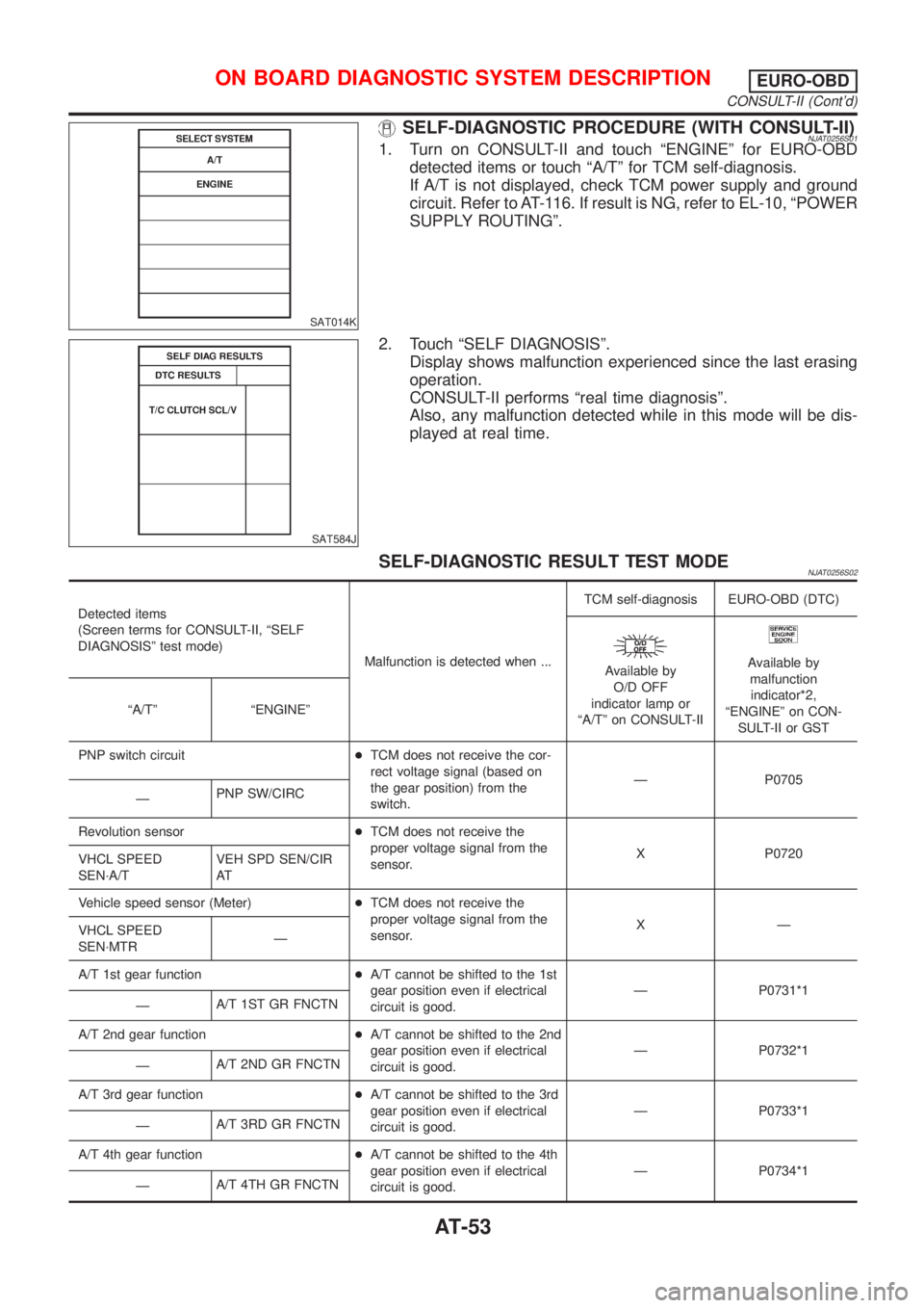
SAT014K
SELF-DIAGNOSTIC PROCEDURE (WITH CONSULT-II)NJAT0256S011. Turn on CONSULT-II and touch ªENGINEº for EURO-OBD
detected items or touch ªA/Tº for TCM self-diagnosis.
If A/T is not displayed, check TCM power supply and ground
circuit. Refer to AT-116. If result is NG, refer to EL-10, ªPOWER
SUPPLY ROUTINGº.
SAT584J
2. Touch ªSELF DIAGNOSISº.
Display shows malfunction experienced since the last erasing
operation.
CONSULT-II performs ªreal time diagnosisº.
Also, any malfunction detected while in this mode will be dis-
played at real time.
SELF-DIAGNOSTIC RESULT TEST MODENJAT0256S02
Detected items
(Screen terms for CONSULT-II, ªSELF
DIAGNOSISº test mode)
Malfunction is detected when ...TCM self-diagnosis EURO-OBD (DTC)
Available by
O/D OFF
indicator lamp or
ªA/Tº on CONSULT-IIAvailable by
malfunction
indicator*2,
ªENGINEº on CON-
SULT-II or GST ªA/Tº ªENGINEº
PNP switch circuit+TCM does not receive the cor-
rect voltage signal (based on
the gear position) from the
switch.Ð P0705
ÐPNP SW/CIRC
Revolution sensor+TCM does not receive the
proper voltage signal from the
sensor.X P0720
VHCL SPEED
SEN´A/TVEH SPD SEN/CIR
AT
Vehicle speed sensor (Meter)+TCM does not receive the
proper voltage signal from the
sensor.XÐ
VHCL SPEED
SEN´MTRÐ
A/T 1st gear function+A/T cannot be shifted to the 1st
gear position even if electrical
circuit is good.Ð P0731*1
ÐA/T 1ST GR FNCTN
A/T 2nd gear function+A/T cannot be shifted to the 2nd
gear position even if electrical
circuit is good.Ð P0732*1
ÐA/T 2ND GR FNCTN
A/T 3rd gear function+A/T cannot be shifted to the 3rd
gear position even if electrical
circuit is good.Ð P0733*1
ÐA/T 3RD GR FNCTN
A/T 4th gear function+A/T cannot be shifted to the 4th
gear position even if electrical
circuit is good.Ð P0734*1
ÐA/T 4TH GR FNCTN
ON BOARD DIAGNOSTIC SYSTEM DESCRIPTIONEURO-OBD
CONSULT-II (Cont'd)
AT-53
Page 1241 of 2493
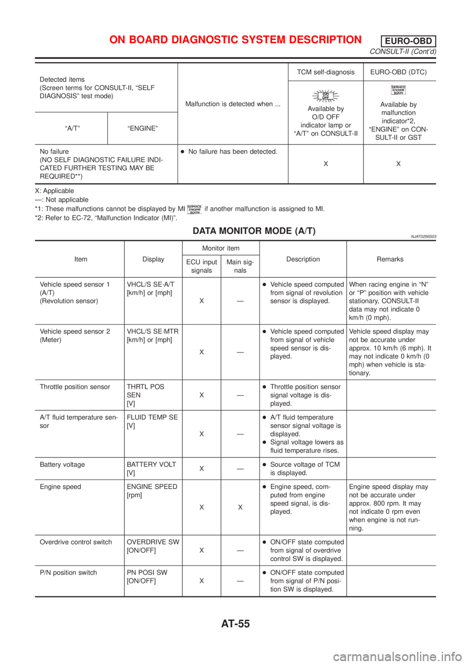
Detected items
(Screen terms for CONSULT-II, ªSELF
DIAGNOSISº test mode)
Malfunction is detected when ...TCM self-diagnosis EURO-OBD (DTC)
Available by
O/D OFF
indicator lamp or
ªA/Tº on CONSULT-IIAvailable by
malfunction
indicator*2,
ªENGINEº on CON-
SULT-II or GST ªA/Tº ªENGINEº
No failure
(NO SELF DIAGNOSTIC FAILURE INDI-
CATED FURTHER TESTING MAY BE
REQUIRED**)+No failure has been detected.
XX
X: Applicable
Ð: Not applicable
*1: These malfunctions cannot be displayed by MI
if another malfunction is assigned to MI.
*2: Refer to EC-72, ªMalfunction Indicator (MI)º.
DATA MONITOR MODE (A/T)NJAT0256S03
Item DisplayMonitor item
Description Remarks
ECU input
signalsMain sig-
nals
Vehicle speed sensor 1
(A/T)
(Revolution sensor)VHCL/S SE´A/T
[km/h] or [mph]
XÐ+Vehicle speed computed
from signal of revolution
sensor is displayed.When racing engine in ªNº
or ªPº position with vehicle
stationary, CONSULT-II
data may not indicate 0
km/h (0 mph).
Vehicle speed sensor 2
(Meter)VHCL/S SE´MTR
[km/h] or [mph]
XÐ+Vehicle speed computed
from signal of vehicle
speed sensor is dis-
played.Vehicle speed display may
not be accurate under
approx. 10 km/h (6 mph). It
may not indicate 0 km/h (0
mph) when vehicle is sta-
tionary.
Throttle position sensor THRTL POS
SEN
[V]XÐ+Throttle position sensor
signal voltage is dis-
played.
A/T fluid temperature sen-
sorFLUID TEMP SE
[V]
XÐ+A/T fluid temperature
sensor signal voltage is
displayed.
+Signal voltage lowers as
fluid temperature rises.
Battery voltage BATTERY VOLT
[V]XÐ+Source voltage of TCM
is displayed.
Engine speed ENGINE SPEED
[rpm]
XX+Engine speed, com-
puted from engine
speed signal, is dis-
played.Engine speed display may
not be accurate under
approx. 800 rpm. It may
not indicate 0 rpm even
when engine is not run-
ning.
Overdrive control switch OVERDRIVE SW
[ON/OFF] X Ð+ON/OFF state computed
from signal of overdrive
control SW is displayed.
P/N position switch PN POSI SW
[ON/OFF] X Ð+ON/OFF state computed
from signal of P/N posi-
tion SW is displayed.
ON BOARD DIAGNOSTIC SYSTEM DESCRIPTIONEURO-OBD
CONSULT-II (Cont'd)
AT-55