2001 NISSAN ALMERA N16 Meter
[x] Cancel search: MeterPage 1761 of 2493
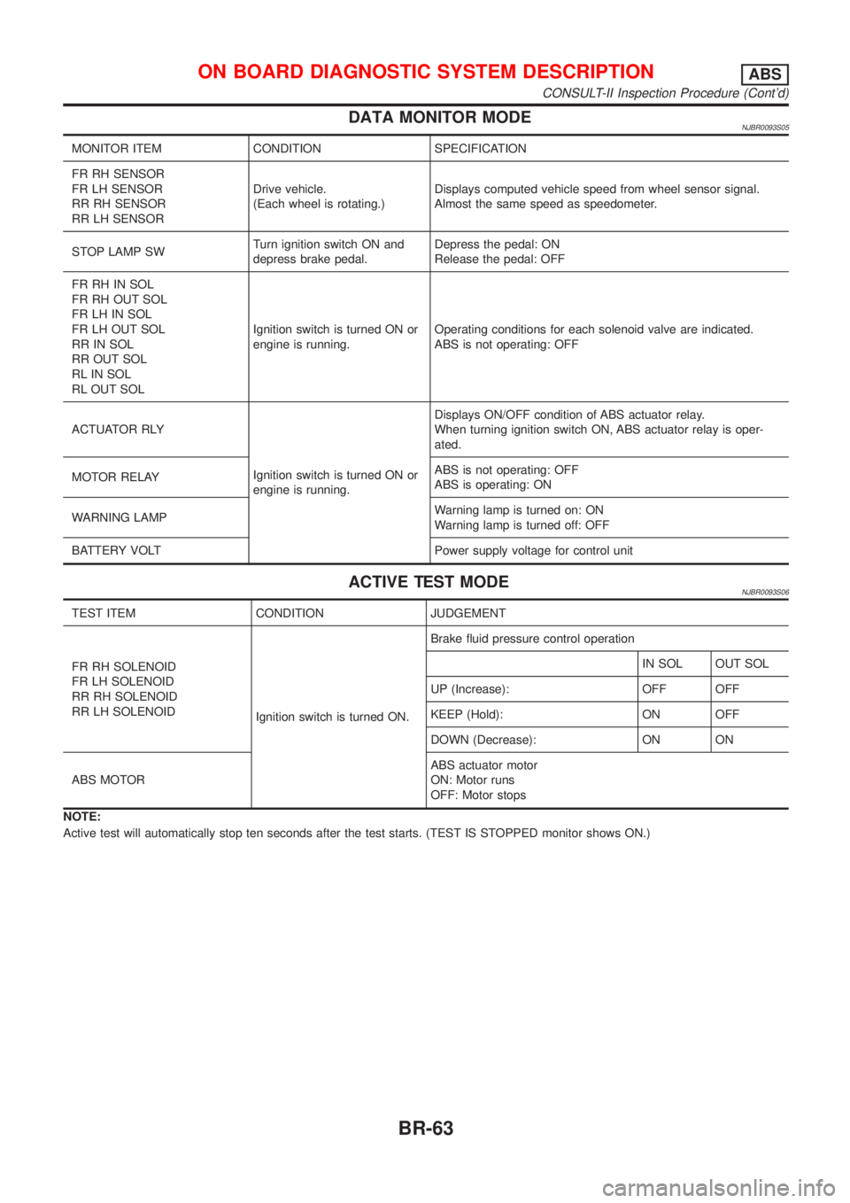
DATA MONITOR MODENJBR0093S05
MONITOR ITEM CONDITION SPECIFICATION
FR RH SENSOR
FR LH SENSOR
RR RH SENSOR
RR LH SENSORDrive vehicle.
(Each wheel is rotating.)Displays computed vehicle speed from wheel sensor signal.
Almost the same speed as speedometer.
STOP LAMP SWTurn ignition switch ON and
depress brake pedal.Depress the pedal: ON
Release the pedal: OFF
FR RH IN SOL
FR RH OUT SOL
FR LH IN SOL
FR LH OUT SOL
RR IN SOL
RR OUT SOL
RL IN SOL
RL OUT SOLIgnition switch is turned ON or
engine is running.Operating conditions for each solenoid valve are indicated.
ABS is not operating: OFF
ACTUATOR RLY
Ignition switch is turned ON or
engine is running.Displays ON/OFF condition of ABS actuator relay.
When turning ignition switch ON, ABS actuator relay is oper-
ated.
MOTOR RELAYABS is not operating: OFF
ABS is operating: ON
WARNING LAMPWarning lamp is turned on: ON
Warning lamp is turned off: OFF
BATTERY VOLT Power supply voltage for control unit
ACTIVE TEST MODENJBR0093S06
TEST ITEM CONDITION JUDGEMENT
FR RH SOLENOID
FR LH SOLENOID
RR RH SOLENOID
RR LH SOLENOID
Ignition switch is turned ON.Brake fluid pressure control operation
IN SOL OUT SOL
UP (Increase): OFF OFF
KEEP (Hold): ON OFF
DOWN (Decrease): ON ON
ABS MOTORABS actuator motor
ON: Motor runs
OFF: Motor stops
NOTE:
Active test will automatically stop ten seconds after the test starts. (TEST IS STOPPED monitor shows ON.)
ON BOARD DIAGNOSTIC SYSTEM DESCRIPTIONABS
CONSULT-II Inspection Procedure (Cont'd)
BR-63
Page 1783 of 2493
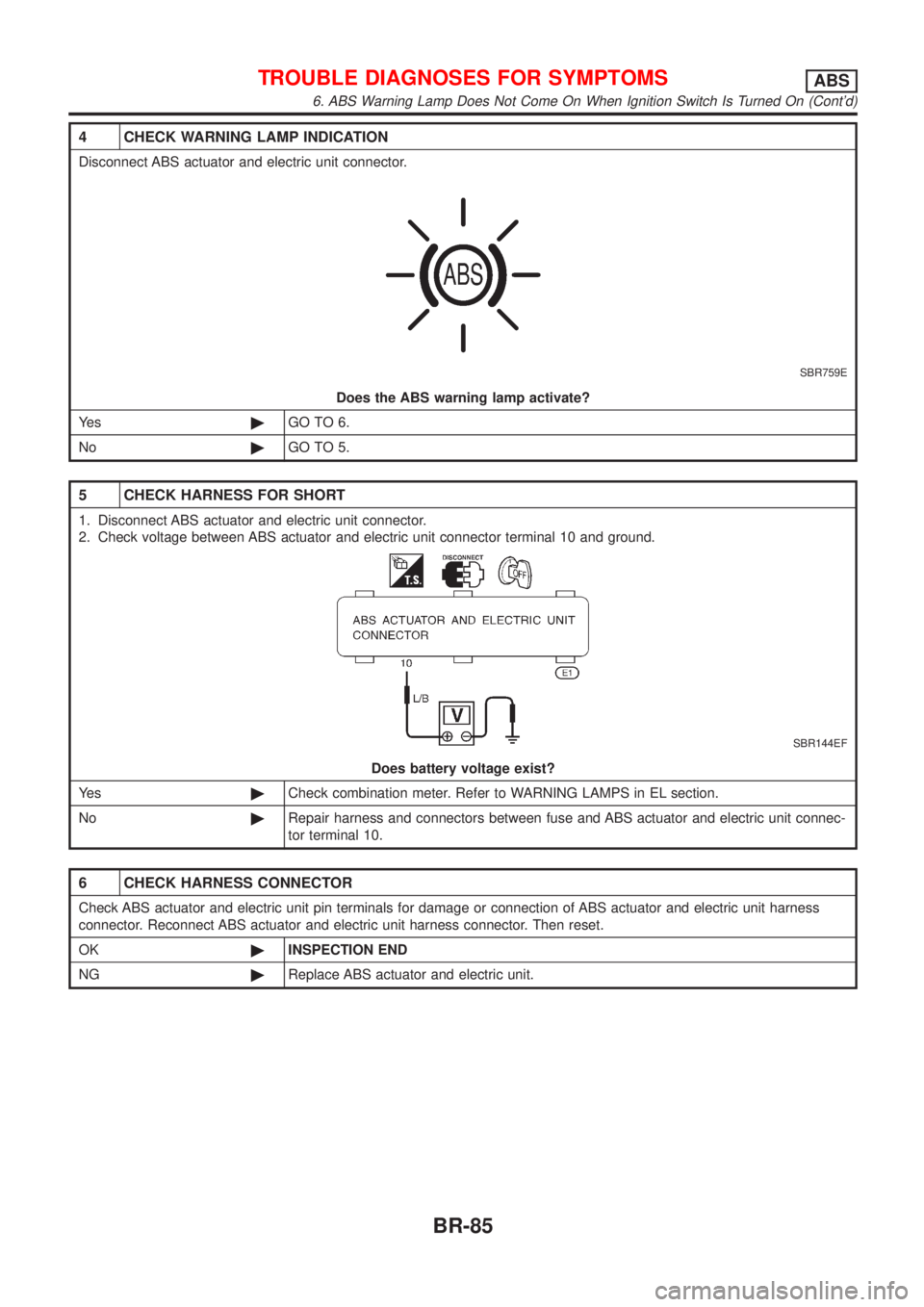
4 CHECK WARNING LAMP INDICATION
Disconnect ABS actuator and electric unit connector.
SBR759E
Does the ABS warning lamp activate?
Ye s©GO TO 6.
No©GO TO 5.
5 CHECK HARNESS FOR SHORT
1. Disconnect ABS actuator and electric unit connector.
2. Check voltage between ABS actuator and electric unit connector terminal 10 and ground.
SBR144EF
Does battery voltage exist?
Ye s©Check combination meter. Refer to WARNING LAMPS in EL section.
No©Repair harness and connectors between fuse and ABS actuator and electric unit connec-
tor terminal 10.
6 CHECK HARNESS CONNECTOR
Check ABS actuator and electric unit pin terminals for damage or connection of ABS actuator and electric unit harness
connector. Reconnect ABS actuator and electric unit harness connector. Then reset.
OK©INSPECTION END
NG©Replace ABS actuator and electric unit.
TROUBLE DIAGNOSES FOR SYMPTOMSABS
6. ABS Warning Lamp Does Not Come On When Ignition Switch Is Turned On (Cont'd)
BR-85
Page 1784 of 2493
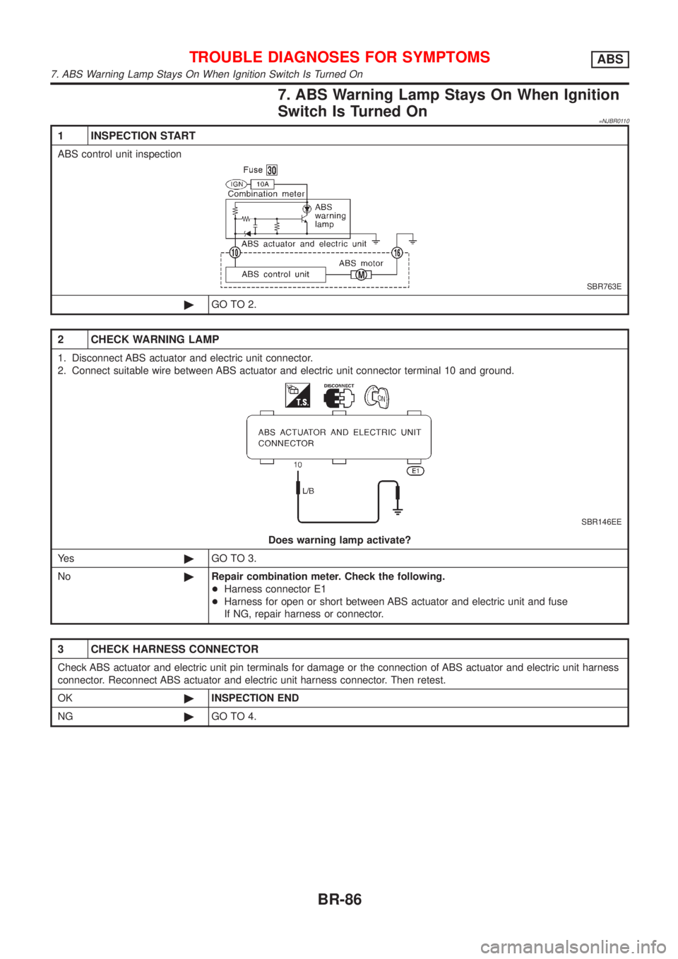
7. ABS Warning Lamp Stays On When Ignition
Switch Is Turned On
=NJBR0110
1 INSPECTION START
ABS control unit inspection
SBR763E
©GO TO 2.
2 CHECK WARNING LAMP
1. Disconnect ABS actuator and electric unit connector.
2. Connect suitable wire between ABS actuator and electric unit connector terminal 10 and ground.
SBR146EE
Does warning lamp activate?
Ye s©GO TO 3.
No©Repair combination meter. Check the following.
+Harness connector E1
+Harness for open or short between ABS actuator and electric unit and fuse
If NG, repair harness or connector.
3 CHECK HARNESS CONNECTOR
Check ABS actuator and electric unit pin terminals for damage or the connection of ABS actuator and electric unit harness
connector. Reconnect ABS actuator and electric unit harness connector. Then retest.
OK©INSPECTION END
NG©GO TO 4.
TROUBLE DIAGNOSES FOR SYMPTOMSABS
7. ABS Warning Lamp Stays On When Ignition Switch Is Turned On
BR-86
Page 1789 of 2493
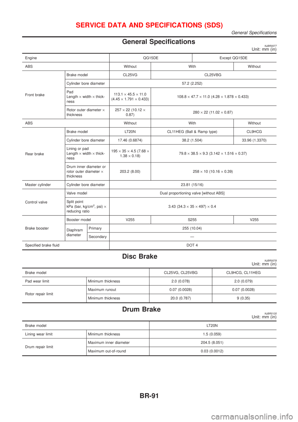
General SpecificationsNJBR0077Unit: mm (in)
Engine QG15DE Except QG15DE
ABS Without With Without
Front brakeBrake model CL25VG CL25VBG
Cylinder bore diameter 57.2 (2.252)
Pad
Length´width´thick-
ness113.1´45.5´11.0
(4.45´1.791´0.433)108.8´47.7´11.0 (4.28´1.878´0.433)
Rotor outer diameter´
thickness257´22 (10.12´
0.87)280´22 (11.02´0.87)
ABS Without With Without
Rear brakeBrake model LT20N CL11HEG (Ball & Ramp type) CL9HCG
Cylinder bore diameter 17.46 (0.6874) 38.2 (1.504) 33.96 (1.3370)
Lining or pad
Length´width´thick-
ness195´35´4.5 (7.68´
1.38´0.18)79.8´38.5´9.3 (3.142´1.516´0.37)
Drum inner diameter or
rotor outer diameter´
thickness203.2 (8.00) 258´10 (10.16´0.39)
Master cylinder Cylinder bore diameter 23.81 (15/16)
Control valveValve model Dual proportioning valve [without ABS]
Split point
kPa (bar, kg/cm
2, psi)´
reducing ratio3.43 (34.3´35´497)´0.4
Brake boosterBooster model V255 S255 V255
Diaphram
diameterPrimary 255 (10.04)
Secondary Ð
Specified brake fluidDOT 4
Disc BrakeNJBR0078Unit: mm (in)
Brake model CL25VG, CL25VBG CL9HCG, CL11HEG
Pad wear limit Minimum thickness 2.0 (0.078) 2.0 (0.079)
Rotor repair limitMaximum runout 0.07 (0.0028) 0.07 (0.0028)
Minimum thickness 20.0 (0.787) 9 (0.35)
Drum BrakeNJBR0135Unit: mm (in)
Brake modelLT20N
Lining wear limit Minimum thickness 1.5 (0.059)
Drum repair limitMaximum inner diameter 204.5 (8.051)
Maximum out-of-round 0.03 (0.0012)
SERVICE DATA AND SPECIFICATIONS (SDS)
General Specifications
BR-91
Page 1808 of 2493
SST051C
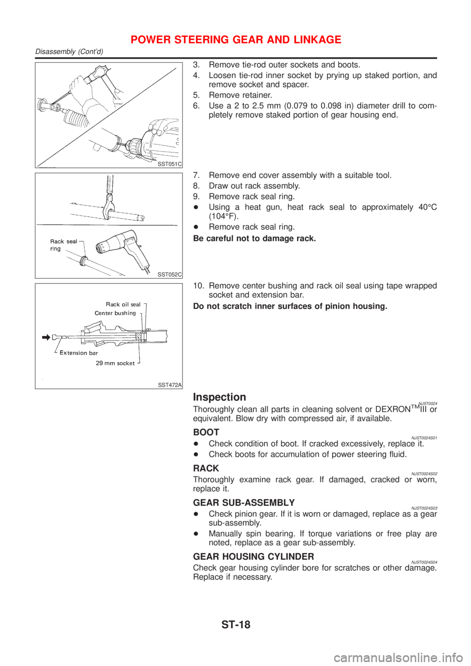
3. Remove tie-rod outer sockets and boots.
4. Loosen tie-rod inner socket by prying up staked portion, and
remove socket and spacer.
5. Remove retainer.
6. Usea2to2.5mm(0.079 to 0.098 in) diameter drill to com-
pletely remove staked portion of gear housing end.
SST052C
7. Remove end cover assembly with a suitable tool.
8. Draw out rack assembly.
9. Remove rack seal ring.
+Using a heat gun, heat rack seal to approximately 40ÉC
(104ÉF).
+Remove rack seal ring.
Be careful not to damage rack.
SST472A
10. Remove center bushing and rack oil seal using tape wrapped
socket and extension bar.
Do not scratch inner surfaces of pinion housing.
InspectionNJST0024Thoroughly clean all parts in cleaning solvent or DEXRONTMIII or
equivalent. Blow dry with compressed air, if available.
BOOTNJST0024S01+Check condition of boot. If cracked excessively, replace it.
+Check boots for accumulation of power steering fluid.
RACKNJST0024S02Thoroughly examine rack gear. If damaged, cracked or worn,
replace it.
GEAR SUB-ASSEMBLYNJST0024S03+Check pinion gear. If it is worn or damaged, replace as a gear
sub-assembly.
+Manually spin bearing. If torque variations or free play are
noted, replace as a gear sub-assembly.
GEAR HOUSING CYLINDERNJST0024S04Check gear housing cylinder bore for scratches or other damage.
Replace if necessary.
POWER STEERING GEAR AND LINKAGE
Disassembly (Cont'd)
ST-18
Page 1855 of 2493

Disposal of Air Bag Module and Seat Belt Pre-
tensioner
NJRS0022+Before disposing of air bag module and seat belt pre-tensioner,
or vehicles equipped with such systems, deploy the systems.
If such systems have already been deployed due to an
accident, dispose of them as indicated in ªDISPOSING OF AIR
BAG MODULE AND SEAT BELT PRE-TENSIONERº (RS-40).
+When deploying the air bag module and seat belt pre-
tensioner, always use the Special Service Tool; Deployment
tool KV99106400.
+When deploying the air bag module and seat belt pre-
tensioner, stand at least 5 m (16 ft) away from the deployment
component.
+When deploying air bag module and seat belt pre-tensioner, a
fairly loud noise is made, followed by smoke being released.
The smoke is not poisonous, however, be careful not to inhale
smoke since it irritates the throat and can cause choking.
+Always activate one air bag module at a time.
+Due to heat, leave air bag module unattended for more than
30 minutes after deployment. Also leave seat belt pre-ten-
sioner unattended for move than 10 minutes after deployment.
+Be sure to wear gloves when handling a deployed air bag
module and seat belt pre-tensioner.
+Never apply water to the deployed air bag module and seat
belt pre-tensioner.
+Wash your hands clean after finishing work.
+Place the vehicle outdoors with an open space of at least 6 m
(20 ft) on all sides when deploying air bag module and seat belt
pre-tensioner while mounted in vehicle.
+Use a voltmeter to make sure the vehicle battery is fully
charged.
+Do not dispose of the air bag module and seat belt pre-ten-
sioner un-deployed.
SRS005-B
CHECKING DEPLOYMENT TOOLNJRS0022S01Connecting to BatteryNJRS0022S0101CAUTION:
The battery must show voltage of 9.6V or more.
Remove the battery from the vehicle and place it on dry wood
blocks approximately 5 m (16 ft) away from the vehicle.
+Wait 3 minutes after the vehicle battery is disconnected before
proceeding.
+Connect red clip of deployment tool to battery positive termi-
nal and black clip to negative terminal.
Make sure the polarity is correct. The right side lamp in the
tool, marked ªdeployment tool powerº, should glow with a
green light. If the right side lamp glows red, reverse the con-
nections to the battery.
SUPPLEMENTAL RESTRAINT SYSTEM (SRS)
Disposal of Air Bag Module and Seat Belt Pre-tensioner
RS-35
Page 1856 of 2493
SBF266H
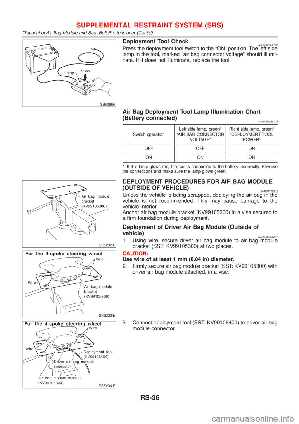
Deployment Tool CheckNJRS0022S0102Press the deployment tool switch to the ªONº position. The left side
lamp in the tool, marked ªair bag connector voltageº should illumi-
nate. If it does not illuminate, replace the tool.
Air Bag Deployment Tool Lamp Illumination Chart
(Battery connected)
NJRS0022S0103
Switch operationLeft side lamp, green*
ªAIR BAG CONNECTOR
VOLTAGEºRight side lamp, green*
ªDEPLOYMENT TOOL
POWERº
OFF OFF ON
ON ON ON
*: If this lamp glows red, the tool is connected to the battery incorrectly. Reverse
the connections and make sure the lamp glows green.
SRS232-E
SRS233-E
DEPLOYMENT PROCEDURES FOR AIR BAG MODULE
(OUTSIDE OF VEHICLE)
NJRS0022S02Unless the vehicle is being scrapped, deploying the air bag in the
vehicle is not recommended. This may cause damage to the
vehicle interior.
Anchor air bag module bracket (KV99105300) in a vise secured to
a firm foundation during deployment.
Deployment of Driver Air Bag Module (Outside of
vehicle)
NJRS0022S02011. Using wire, secure driver air bag module to air bag module
bracket (SST: KV99105300) at two places.
CAUTION:
Use wire of at least 1 mm (0.04 in) diameter.
2. Firmly secure air bag module bracket (SST: KV99105300) with
driver air bag module attached, in a vise.
SRS234-E
3. Connect deployment tool (SST: KV99106400) to driver air bag
module connector.
SUPPLEMENTAL RESTRAINT SYSTEM (SRS)
Disposal of Air Bag Module and Seat Belt Pre-tensioner (Cont'd)
RS-36
Page 1857 of 2493
SRS020-A
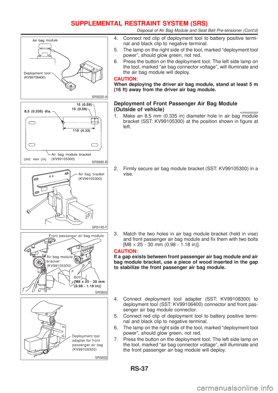
4. Connect red clip of deployment tool to battery positive termi-
nal and black clip to negative terminal.
5. The lamp on the right side of the tool, marked ªdeployment tool
powerº, should glow green, not red.
6. Press the button on the deployment tool. The left side lamp on
the tool, marked ªair bag connector voltageº, will illuminate and
the air bag module will deploy.
CAUTION:
When deploying the driver air bag module, stand at least 5 m
(16 ft) away from the driver air bag module.
SRS685-B
Deployment of Front Passenger Air Bag Module
(Outside of vehicle)
NJRS0022S02021. Make an 8.5 mm (0.335 in) diameter hole in air bag module
bracket (SST: KV99105300) at the position shown in figure at
left.
SRS145-F
2. Firmly secure air bag module bracket (SST: KV99105300) in a
vise.
SRS833
3. Match the two holes in air bag module bracket (held in vise)
and front passenger air bag module and fix them with two bolts
[M8´25 - 30 mm (0.98 - 1.18 in)].
CAUTION:
If a gap exists between front passenger air bag module and air
bag module bracket, use a piece of wood inserted in the gap
to stabilize the front passenger air bag module.
SRS832
4. Connect deployment tool adapter (SST: KV99108300) to
deployment tool (SST: KV99106400) connector and front pas-
senger air bag module connector.
5. Connect red clip of deployment tool to battery positive termi-
nal and black clip to negative terminal.
6. The lamp on the right side of the tool, marked ªdeployment tool
powerº, should glow green, not red.
7. Press the button on the deployment tool. The left side lamp on
the tool, marked ªair bag connector voltageº, will illuminate and
the front passenger air bag module will deploy.
SUPPLEMENTAL RESTRAINT SYSTEM (SRS)
Disposal of Air Bag Module and Seat Belt Pre-tensioner (Cont'd)
RS-37