2001 NISSAN ALMERA N16 Meter
[x] Cancel search: MeterPage 2107 of 2493
INSTALLATIONNJSC0013S02To install, reverse the removal procedure.
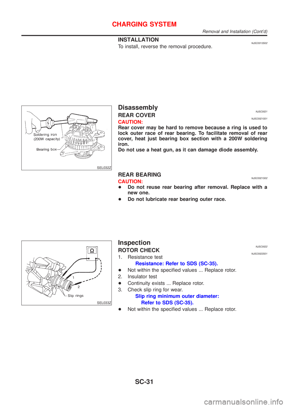
SEL032Z
DisassemblyNJSC0021REAR COVERNJSC0021S01CAUTION:
Rear cover may be hard to remove because a ring is used to
lock outer race of rear bearing. To facilitate removal of rear
cover, heat just bearing box section with a 200W soldering
iron.
Do not use a heat gun, as it can damage diode assembly.
REAR BEARINGNJSC0021S02CAUTION:
+Do not reuse rear bearing after removal. Replace with a
new one.
+Do not lubricate rear bearing outer race.
SEL033Z
InspectionNJSC0022ROTOR CHECKNJSC0022S011. Resistance test
Resistance: Refer to SDS (SC-35).
+Not within the specified values ... Replace rotor.
2. Insulator test
+Continuity exists ... Replace rotor.
3. Check slip ring for wear.
Slip ring minimum outer diameter:
Refer to SDS (SC-35).
+Not within the specified values ... Replace rotor.
CHARGING SYSTEM
Removal and Installation (Cont'd)
SC-31
Page 2110 of 2493
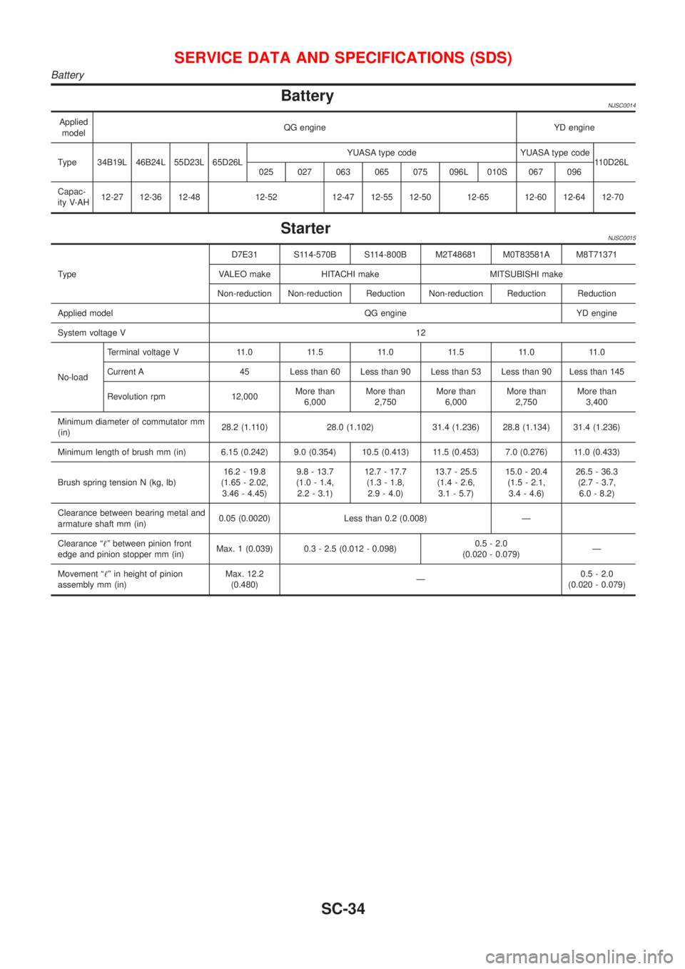
BatteryNJSC0014
Applied
modelQG engine YD engine
Type 34B19L 46B24L 55D23L 65D26LYUASA type code YUASA type code
110D26L
025 027 063 065 075 096L 010S 067 096
Capac-
ity V-AH12-27 12-36 12-48 12-52 12-47 12-55 12-50 12-65 12-60 12-64 12-70
StarterNJSC0015
TypeD7E31 S114-570B S114-800B M2T48681 M0T83581A M8T71371
VALEO make HITACHI make MITSUBISHI make
Non-reduction Non-reduction Reduction Non-reduction Reduction Reduction
Applied model QG engine YD engine
System voltage V12
No-loadTerminal voltage V 11.0 11.5 11.0 11.5 11.0 11.0
Current A 45 Less than 60 Less than 90 Less than 53 Less than 90 Less than 145
Revolution rpm 12,000More than
6,000More than
2,750More than
6,000More than
2,750More than
3,400
Minimum diameter of commutator mm
(in)28.2 (1.110) 28.0 (1.102) 31.4 (1.236) 28.8 (1.134) 31.4 (1.236)
Minimum length of brush mm (in) 6.15 (0.242) 9.0 (0.354) 10.5 (0.413) 11.5 (0.453) 7.0 (0.276) 11.0 (0.433)
Brush spring tension N (kg, lb)16.2 - 19.8
(1.65 - 2.02,
3.46 - 4.45)9.8 - 13.7
(1.0 - 1.4,
2.2 - 3.1)12.7 - 17.7
(1.3 - 1.8,
2.9 - 4.0)13.7 - 25.5
(1.4 - 2.6,
3.1 - 5.7)15.0 - 20.4
(1.5 - 2.1,
3.4 - 4.6)26.5 - 36.3
(2.7 - 3.7,
6.0 - 8.2)
Clearance between bearing metal and
armature shaft mm (in)0.05 (0.0020) Less than 0.2 (0.008) Ð
Clearance ª!º between pinion front
edge and pinion stopper mm (in)Max. 1 (0.039) 0.3 - 2.5 (0.012 - 0.098)0.5 - 2.0
(0.020 - 0.079)Ð
Movement ª!º in height of pinion
assembly mm (in)Max. 12.2
(0.480)Ð0.5 - 2.0
(0.020 - 0.079)
SERVICE DATA AND SPECIFICATIONS (SDS)
Battery
SC-34
Page 2111 of 2493
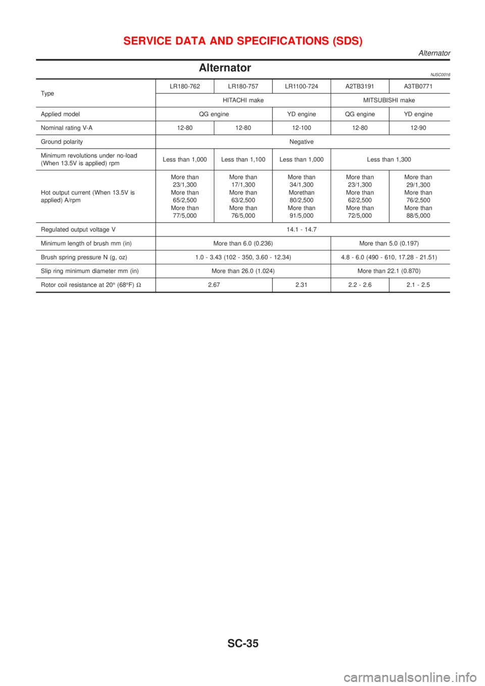
AlternatorNJSC0016
TypeLR180-762 LR180-757 LR1100-724 A2TB3191 A3TB0771
HITACHI make MITSUBISHI make
Applied model QG engine YD engine QG engine YD engine
Nominal rating V-A 12-80 12-80 12-100 12-80 12-90
Ground polarityNegative
Minimum revolutions under no-load
(When 13.5V is applied) rpmLess than 1,000 Less than 1,100 Less than 1,000 Less than 1,300
Hot output current (When 13.5V is
applied) A/rpmMore than
23/1,300
More than
65/2,500
More than
77/5,000More than
17/1,300
More than
63/2,500
More than
76/5,000More than
34/1,300
Morethan
80/2,500
More than
91/5,000More than
23/1,300
More than
62/2,500
More than
72/5,000More than
29/1,300
More than
76/2,500
More than
88/5,000
Regulated output voltage V 14.1 - 14.7
Minimum length of brush mm (in) More than 6.0 (0.236) More than 5.0 (0.197)
Brush spring pressure N (g, oz) 1.0 - 3.43 (102 - 350, 3.60 - 12.34) 4.8 - 6.0 (490 - 610, 17.28 - 21.51)
Slip ring minimum diameter mm (in) More than 26.0 (1.024) More than 22.1 (0.870)
Rotor coil resistance at 20É (68ÉF)W2.67 2.31 2.2 - 2.6 2.1 - 2.5
SERVICE DATA AND SPECIFICATIONS (SDS)
Alternator
SC-35
Page 2113 of 2493
ELECTRICAL SYSTEM
SECTION
EL
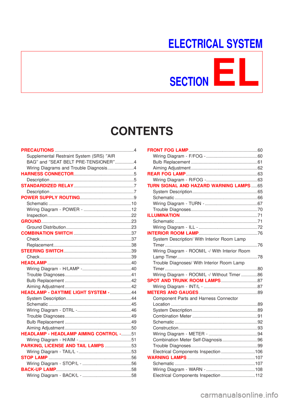
CONTENTS
PRECAUTIONS...............................................................4
Supplemental Restraint System (SRS)²AIR
BAG²and²SEAT BELT PRE-TENSIONER²...............4
Wiring Diagrams and Trouble Diagnosis .....................4
HARNESS CONNECTOR................................................5
Description ...................................................................5
STANDARDIZED RELAY................................................7
Description ...................................................................7
POWER SUPPLY ROUTING...........................................9
Schematic ..................................................................10
Wiring Diagram - POWER - ......................................12
Inspection...................................................................22
GROUND........................................................................23
Ground Distribution ....................................................23
COMBINATION SWITCH..............................................37
Check .........................................................................37
Replacement ..............................................................38
STEERING SWITCH......................................................39
Check .........................................................................39
HEADLAMP...................................................................40
Wiring Diagram - H/LAMP -.......................................40
Trouble Diagnoses.....................................................41
Bulb Replacement .....................................................42
Aiming Adjustment .....................................................42
HEADLAMP - DAYTIME LIGHT SYSTEM -.................44
System Description ....................................................44
Schematic ..................................................................45
Wiring Diagram - DTRL - ...........................................46
Trouble Diagnoses.....................................................49
Bulb Replacement .....................................................49
Aiming Adjustment .....................................................50
HEADLAMP - HEADLAMP AIMING CONTROL -........51
Wiring Diagram - H/AIM - ..........................................51
PARKING, LICENSE AND TAIL LAMPS.....................53
Wiring Diagram - TAIL/L - ..........................................53
STOP LAMP..................................................................56
Wiring Diagram - STOP/L - .......................................56
BACK-UP LAMP............................................................58
Wiring Diagram - BACK/L - .......................................58FRONT FOG LAMP.......................................................60
Wiring Diagram - F/FOG - .........................................60
Bulb Replacement .....................................................61
Aiming Adjustment .....................................................62
REAR FOG LAMP.........................................................63
Wiring Diagram - R/FOG -.........................................63
TURN SIGNAL AND HAZARD WARNING LAMPS.....65
System Description ....................................................65
Schematic ..................................................................66
Wiring Diagram - TURN - ..........................................67
Trouble Diagnoses.....................................................70
ILLUMINATION..............................................................71
Schematic ..................................................................71
Wiring Diagram - ILL - ...............................................72
INTERIOR ROOM LAMP...............................................76
System Description/ With Interior Room Lamp
Timer ..........................................................................76
Wiring Diagram - ROOM/L -/ With Interior Room
Lamp Timer ................................................................78
Trouble Diagnoses/ With Interior Room Lamp
Timer ..........................................................................80
Wiring Diagram - ROOM/L -/ Without Timer .............86
SPOT AND TRUNK ROOM LAMPS.............................87
Wiring Diagram - INT/L - ...........................................87
METERS AND GAUGES...............................................89
Component Parts and Harness Connector
Location .....................................................................89
System Description ....................................................89
Combination Meter ....................................................91
Schematic ..................................................................92
Construction ...............................................................93
Wiring Diagram - METER - .......................................94
Combination Meter Self-Diagnosis ............................96
Trouble Diagnoses.....................................................99
Electrical Components Inspection ...........................106
WARNING LAMPS......................................................107
Schematic ................................................................107
Wiring Diagram - WARN - .......................................108
Electrical Components Inspection ........................... 112
Page 2153 of 2493
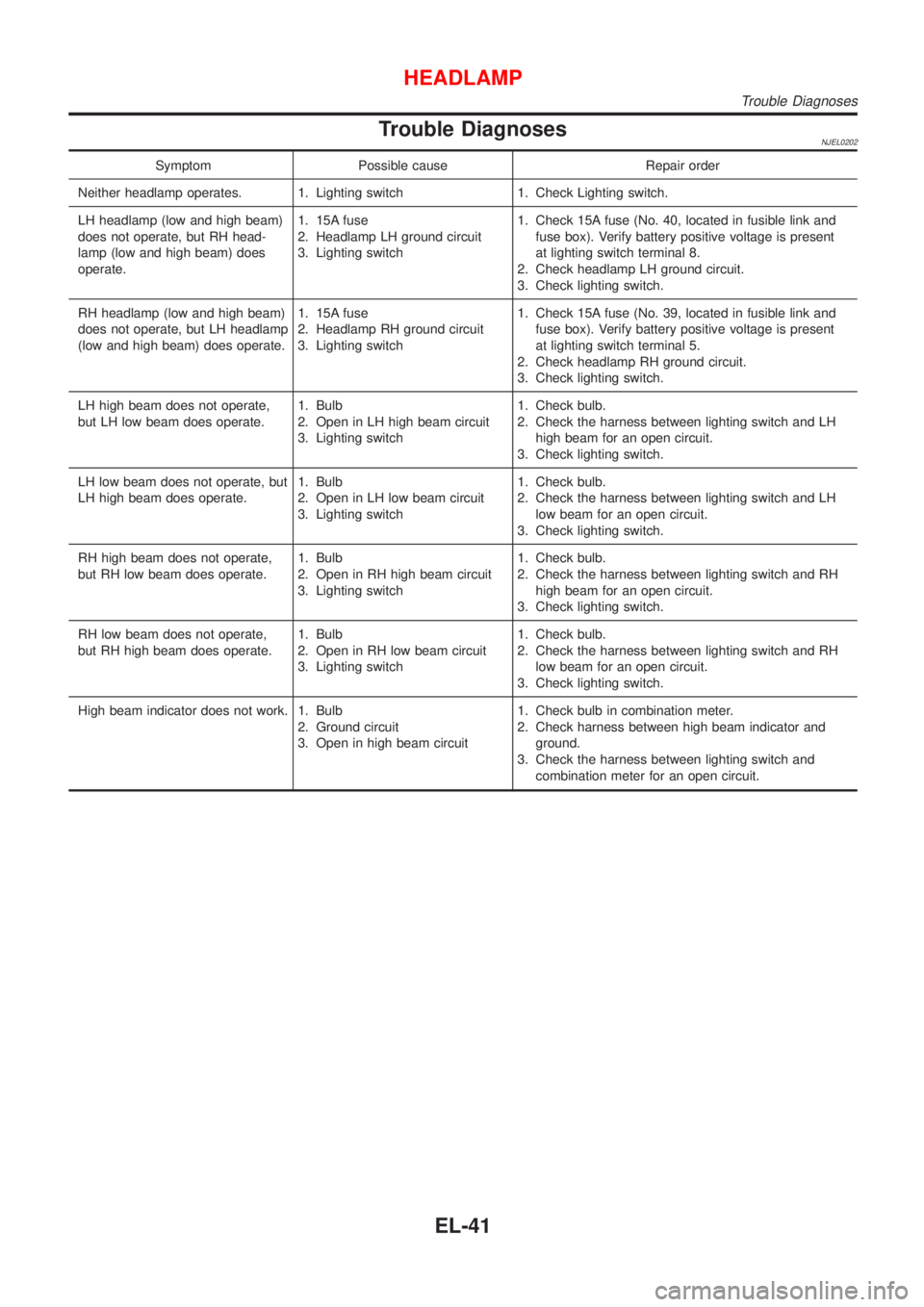
Trouble DiagnosesNJEL0202
Symptom Possible cause Repair order
Neither headlamp operates. 1. Lighting switch 1. Check Lighting switch.
LH headlamp (low and high beam)
does not operate, but RH head-
lamp (low and high beam) does
operate.1. 15A fuse
2. Headlamp LH ground circuit
3. Lighting switch1. Check 15A fuse (No. 40, located in fusible link and
fuse box). Verify battery positive voltage is present
at lighting switch terminal 8.
2. Check headlamp LH ground circuit.
3. Check lighting switch.
RH headlamp (low and high beam)
does not operate, but LH headlamp
(low and high beam) does operate.1. 15A fuse
2. Headlamp RH ground circuit
3. Lighting switch1. Check 15A fuse (No. 39, located in fusible link and
fuse box). Verify battery positive voltage is present
at lighting switch terminal 5.
2. Check headlamp RH ground circuit.
3. Check lighting switch.
LH high beam does not operate,
but LH low beam does operate.1. Bulb
2. Open in LH high beam circuit
3. Lighting switch1. Check bulb.
2. Check the harness between lighting switch and LH
high beam for an open circuit.
3. Check lighting switch.
LH low beam does not operate, but
LH high beam does operate.1. Bulb
2. Open in LH low beam circuit
3. Lighting switch1. Check bulb.
2. Check the harness between lighting switch and LH
low beam for an open circuit.
3. Check lighting switch.
RH high beam does not operate,
but RH low beam does operate.1. Bulb
2. Open in RH high beam circuit
3. Lighting switch1. Check bulb.
2. Check the harness between lighting switch and RH
high beam for an open circuit.
3. Check lighting switch.
RH low beam does not operate,
but RH high beam does operate.1. Bulb
2. Open in RH low beam circuit
3. Lighting switch1. Check bulb.
2. Check the harness between lighting switch and RH
low beam for an open circuit.
3. Check lighting switch.
High beam indicator does not work. 1. Bulb
2. Ground circuit
3. Open in high beam circuit1. Check bulb in combination meter.
2. Check harness between high beam indicator and
ground.
3. Check the harness between lighting switch and
combination meter for an open circuit.
HEADLAMP
Trouble Diagnoses
EL-41
Page 2182 of 2493
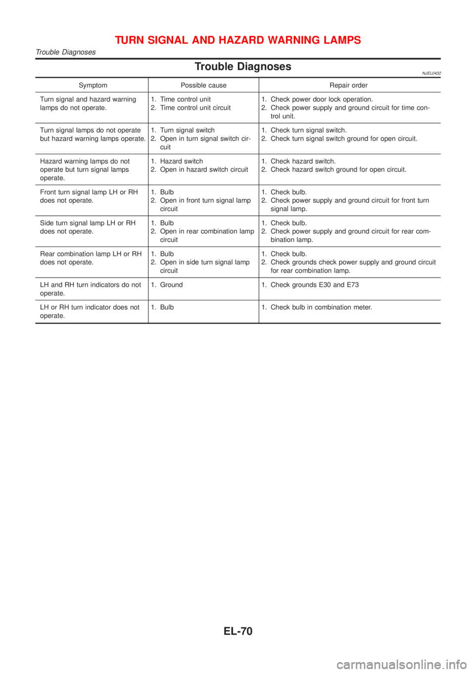
Trouble DiagnosesNJEL0432
Symptom Possible cause Repair order
Turn signal and hazard warning
lamps do not operate.1. Time control unit
2. Time control unit circuit1. Check power door lock operation.
2. Check power supply and ground circuit for time con-
trol unit.
Turn signal lamps do not operate
but hazard warning lamps operate.1. Turn signal switch
2. Open in turn signal switch cir-
cuit1. Check turn signal switch.
2. Check turn signal switch ground for open circuit.
Hazard warning lamps do not
operate but turn signal lamps
operate.1. Hazard switch
2. Open in hazard switch circuit1. Check hazard switch.
2. Check hazard switch ground for open circuit.
Front turn signal lamp LH or RH
does not operate.1. Bulb
2. Open in front turn signal lamp
circuit1. Check bulb.
2. Check power supply and ground circuit for front turn
signal lamp.
Side turn signal lamp LH or RH
does not operate.1. Bulb
2. Open in rear combination lamp
circuit1. Check bulb.
2. Check power supply and ground circuit for rear com-
bination lamp.
Rear combination lamp LH or RH
does not operate.1. Bulb
2. Open in side turn signal lamp
circuit1. Check bulb.
2. Check grounds check power supply and ground circuit
for rear combination lamp.
LH and RH turn indicators do not
operate.1. Ground 1. Check grounds E30 and E73
LH or RH turn indicator does not
operate.1. Bulb 1. Check bulb in combination meter.
TURN SIGNAL AND HAZARD WARNING LAMPS
Trouble Diagnoses
EL-70
Page 2201 of 2493
Component Parts and Harness Connector
Location
NJEL0441For details, refer to ªELECTRICAL UNIT LOCATIONº (EL-319) and
ªHARNESS LAYOUTº (EL-324).
System DescriptionNJEL0442UNIFIED CONTROL METERNJEL0442S01+Speedometer, odo/trip meter, tachometer, fuel gauge and water temperature gauge are controlled totally
by control unit built-in combination meter.
+Digital meter is adopted for odo/trip meter.*
*The record of the odo meter is kept even if the battery cable is disconnected. The record of the trip meter
is erased when the battery cable is disconnected.
+Odo/trip meter segment can be checked in diagnosis mode.
+Meter/gauge can be checked in diagnosis mode.
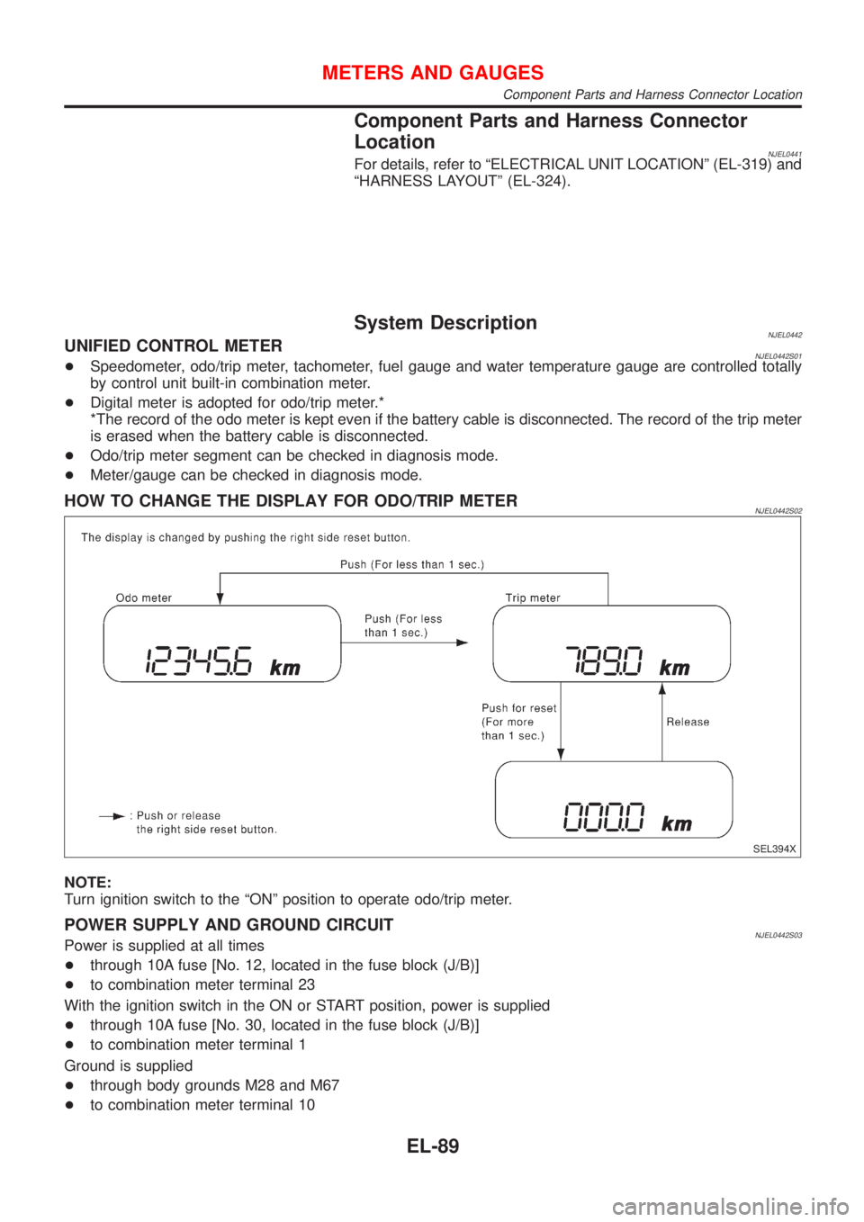
HOW TO CHANGE THE DISPLAY FOR ODO/TRIP METERNJEL0442S02
SEL394X
NOTE:
Turn ignition switch to the ªONº position to operate odo/trip meter.
POWER SUPPLY AND GROUND CIRCUITNJEL0442S03Power is supplied at all times
+through 10A fuse [No. 12, located in the fuse block (J/B)]
+to combination meter terminal 23
With the ignition switch in the ON or START position, power is supplied
+through 10A fuse [No. 30, located in the fuse block (J/B)]
+to combination meter terminal 1
Ground is supplied
+through body grounds M28 and M67
+to combination meter terminal 10
METERS AND GAUGES
Component Parts and Harness Connector Location
EL-89
Page 2202 of 2493
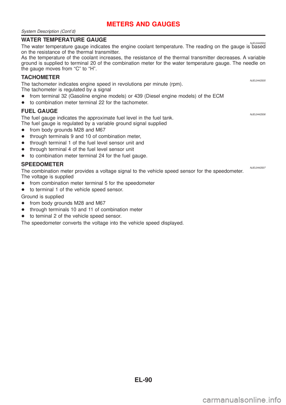
WATER TEMPERATURE GAUGENJEL0442S04The water temperature gauge indicates the engine coolant temperature. The reading on the gauge is based
on the resistance of the thermal transmitter.
As the temperature of the coolant increases, the resistance of the thermal transmitter decreases. A variable
ground is supplied to terminal 20 of the combination meter for the water temperature gauge. The needle on
the gauge moves from ªCº to ªHº.
TACHOMETERNJEL0442S05The tachometer indicates engine speed in revolutions per minute (rpm).
The tachometer is regulated by a signal
+from terminal 32 (Gasoline engine models) or 439 (Diesel engine models) of the ECM
+to combination meter terminal 22 for the tachometer.
FUEL GAUGENJEL0442S06The fuel gauge indicates the approximate fuel level in the fuel tank.
The fuel gauge is regulated by a variable ground signal supplied
+from body grounds M28 and M67
+through terminals 9 and 10 of combination meter,
+through terminal 1 of the fuel level sensor unit and
+through terminal 4 of the fuel level sensor unit
+to combination meter terminal 24 for the fuel gauge.
SPEEDOMETERNJEL0442S07The combination meter provides a voltage signal to the vehicle speed sensor for the speedometer.
The voltage is supplied
+from combination meter terminal 5 for the speedometer
+to terminal 1 of the vehicle speed sensor.
Ground is supplied
+from body grounds M28 and M67
+through terminals 10 and 11 of combination meter
+to teminal 2 of the vehicle speed sensor.
The speedometer converts the voltage into the vehicle speed displayed.
METERS AND GAUGES
System Description (Cont'd)
EL-90