Page 1858 of 2493
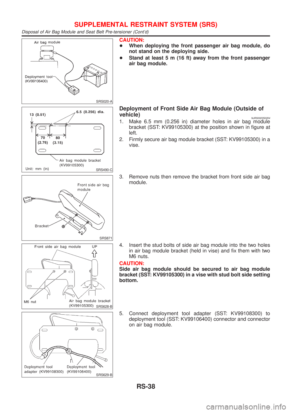
SRS020-A
CAUTION:
+When deploying the front passenger air bag module, do
not stand on the deploying side.
+Stand at least 5 m (16 ft) away from the front passenger
air bag module.
SRS490-C
Deployment of Front Side Air Bag Module (Outside of
vehicle)
NJRS0022S02041. Make 6.5 mm (0.256 in) diameter holes in air bag module
bracket (SST: KV99105300) at the position shown in figure at
left.
2. Firmly secure air bag module bracket (SST: KV99105300) in a
vise.
SRS871
3. Remove nuts then remove the bracket from front side air bag
module.
SRS628-B
4. Insert the stud bolts of side air bag module into the two holes
in air bag module bracket (held in vise) and fix them with two
M6 nuts.
CAUTION:
Side air bag module should be secured to air bag module
bracket (SST: KV99105300) in a vise with stud bolt side setting
bottom.
SRS629-B
5. Connect deployment tool adapter (SST: KV99108300) to
deployment tool (SST: KV99106400) connector and connector
on air bag module.
SUPPLEMENTAL RESTRAINT SYSTEM (SRS)
Disposal of Air Bag Module and Seat Belt Pre-tensioner (Cont'd)
RS-38
Page 1869 of 2493
SRS800
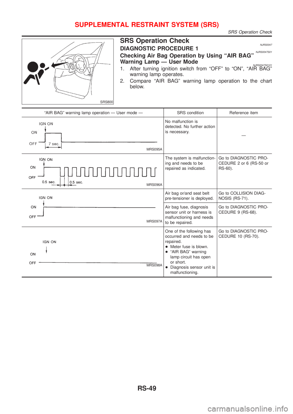
SRS Operation CheckNJRS0047DIAGNOSTIC PROCEDURE 1NJRS0047S01Checking Air Bag Operation by Using ªAIR BAGº
Warning Lamp Ð User Mode
NJRS0047S01011. After turning ignition switch from ªOFFº to ªONº, ªAIR BAGº
warning lamp operates.
2. Compare ªAIR BAGº warning lamp operation to the chart
below.
ªAIR BAGº warning lamp operation Ð User mode Ð SRS condition Reference item
MRS095A
No malfunction is
detected. No further action
is necessary.
Ð
MRS096A
The system is malfunction-
ing and needs to be
repaired as indicated.Go to DIAGNOSTIC PRO-
CEDURE 2 or 6 (RS-50 or
RS-60).
MRS097A
Air bag or/and seat belt
pre-tensioner is deployed.Go to COLLISION DIAG-
NOSIS (RS-71).
Air bag fuse, diagnosis
sensor unit or harness is
malfunctioning and needs
to be repaired.Go to DIAGNOSTIC PRO-
CEDURE 9 (RS-68).
MRS098A
One of the following has
occurred and needs to be
repaired.
+Meter fuse is blown.
+ªAIR BAGº warning
lamp circuit has open
or short.
+Diagnosis sensor unit is
malfunctioning.Go to DIAGNOSTIC PRO-
CEDURE 10 (RS-70).
SUPPLEMENTAL RESTRAINT SYSTEM (SRS)
SRS Operation Check
RS-49
Page 1887 of 2493
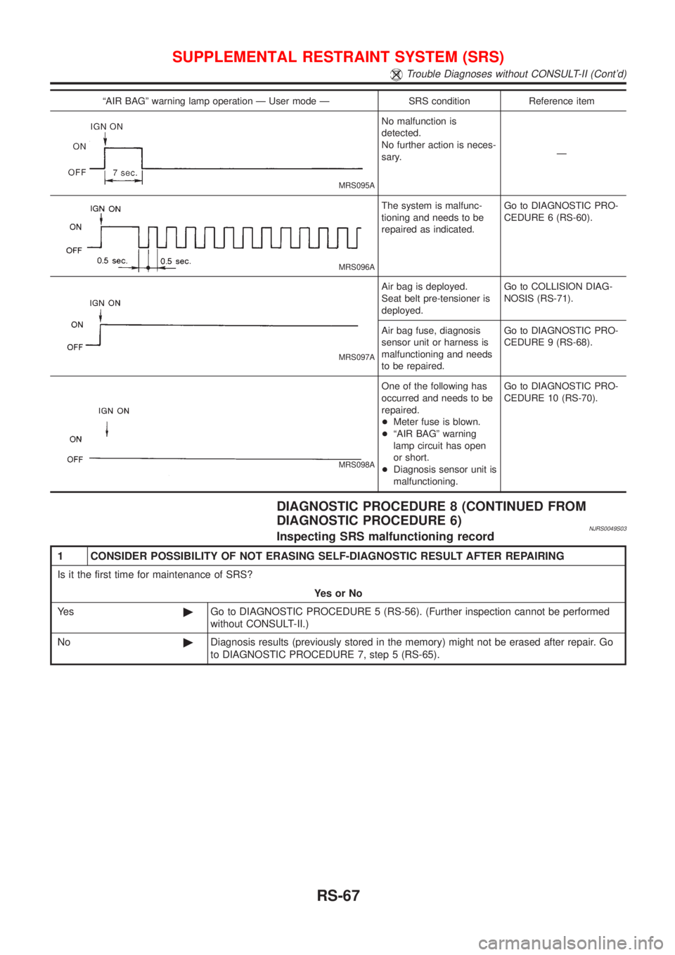
ªAIR BAGº warning lamp operation Ð User mode Ð SRS condition Reference item
MRS095A
No malfunction is
detected.
No further action is neces-
sary.Ð
MRS096A
The system is malfunc-
tioning and needs to be
repaired as indicated.Go to DIAGNOSTIC PRO-
CEDURE 6 (RS-60).
MRS097A
Air bag is deployed.
Seat belt pre-tensioner is
deployed.Go to COLLISION DIAG-
NOSIS (RS-71).
Air bag fuse, diagnosis
sensor unit or harness is
malfunctioning and needs
to be repaired.Go to DIAGNOSTIC PRO-
CEDURE 9 (RS-68).
MRS098A
One of the following has
occurred and needs to be
repaired.
+Meter fuse is blown.
+ªAIR BAGº warning
lamp circuit has open
or short.
+Diagnosis sensor unit is
malfunctioning.Go to DIAGNOSTIC PRO-
CEDURE 10 (RS-70).
DIAGNOSTIC PROCEDURE 8 (CONTINUED FROM
DIAGNOSTIC PROCEDURE 6)
NJRS0049S03Inspecting SRS malfunctioning record
1 CONSIDER POSSIBILITY OF NOT ERASING SELF-DIAGNOSTIC RESULT AFTER REPAIRING
Is it the first time for maintenance of SRS?
YesorNo
Ye s©Go to DIAGNOSTIC PROCEDURE 5 (RS-56). (Further inspection cannot be performed
without CONSULT-II.)
No©Diagnosis results (previously stored in the memory) might not be erased after repair. Go
to DIAGNOSTIC PROCEDURE 7, step 5 (RS-65).
SUPPLEMENTAL RESTRAINT SYSTEM (SRS)
Trouble Diagnoses without CONSULT-II (Cont'd)
RS-67
Page 1890 of 2493
Trouble Diagnoses: ªAIR BAGº Warning Lamp
Does Not Turn On
=NJRS0051DIAGNOSTIC PROCEDURE 10NJRS0051S01
1 CHECK ªMETERº FUSE
Is meter fuse OK?
SRS836
OK or NG
OK©GO TO 3.
NG©GO TO 2.
2 CHECK ªMETERº FUSE AGAIN
Replace meter fuse and turn ignition switch ON.
Is meter fuse blown again?
Ye s©Repair main harness.
No©INSPECTION END
3 CHECK ªAIR BAGº WARNING LAMP LED
Is ªAIR BAGº warning lamp LED OK?
OK or NG
OK©GO TO 4.
NG©Replace ªAIR BAGº warning lamp LED.
4 CHECK HARNESS CONNECTION BETWEEN DIAGNOSIS SENSOR UNIT AND ªAIR BAGº WARNING
LAMP
Disconnect diagnosis sensor unit connector and turn ignition switch ªONº.
+Does ªAIR BAGº warning lamp turn on?
YesorNo
Ye s©Replace diagnosis sensor unit.
No©Check the ground circuit of ªAIR BAGº warning lamp.
SUPPLEMENTAL RESTRAINT SYSTEM (SRS)
Trouble Diagnoses: ªAIR BAGº Warning Lamp Does Not Turn On
RS-70
Page 2080 of 2493
MEL043F
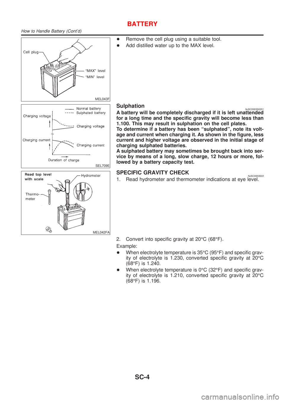
+Remove the cell plug using a suitable tool.
+Add distilled water up to the MAX level.
SEL709E
SulphationNJSC0003S0201A battery will be completely discharged if it is left unattended
for a long time and the specific gravity will become less than
1.100. This may result in sulphation on the cell plates.
To determine if a battery has been ªsulphatedº, note its volt-
age and current when charging it. As shown in the figure, less
current and higher voltage are observed in the initial stage of
charging sulphated batteries.
A sulphated battery may sometimes be brought back into ser-
vice by means of a long, slow charge, 12 hours or more, fol-
lowed by a battery capacity test.
MEL042FA
SPECIFIC GRAVITY CHECKNJSC0003S031. Read hydrometer and thermometer indications at eye level.
2. Convert into specific gravity at 20ÉC (68ÉF).
Example:
+When electrolyte temperature is 35ÉC (95ÉF) and specific grav-
ity of electrolyte is 1.230, converted specific gravity at 20ÉC
(68ÉF) is 1.240.
+When electrolyte temperature is 0ÉC (32ÉF) and specific grav-
ity of electrolyte is 1.210, converted specific gravity at 20ÉC
(68ÉF) is 1.196.
BATTERY
How to Handle Battery (Cont'd)
SC-4
Page 2097 of 2493
SEL018Z
YOKE CHECKNJSC0019S04Magnet is secured to yoke by bonding agent. Check magnet to see
that it is secured to yoke and for any cracks. Replace malfunction-
ing parts as an assembly.
CAUTION:
Do not clamp yoke in a vice or strike it with a hammer.
SEL019Z
ARMATURE CHECKNJSC0019S051. Continuity test (between two segments side by side).
+No continuity ... Replace.
2. Insulation test (between each commutator bar and shaft).
+Continuity exists. ... Replace.
SEL020Z
3. Check commutator surface.
+Rough ... Sand lightly with No. 500 - 600 emery paper.
SEL021Z
4. Check diameter of commutator.
Commutator minimum diameter:
Refer to SDS (SC-34).
+Less than specified value ... Replace.
STARTING SYSTEM
Inspection (Cont'd)
SC-21
Page 2100 of 2493
System DescriptionNJSC0009The alternator provides DC voltage to operate the vehicle's electrical system and to keep the battery charged.
The voltage output is controlled by the IC regulator.
Power is supplied at all times to alternator terminal 4 (S) through:
+10A fuse (No. 33, located in the fuse and fusible link box).
Terminal B supplies power to charge the battery and operate the vehicle's electrical system. Output voltage
is controlled by the IC regulator at terminal 4 (S) detecting the input voltage. The charging circuit is protected
by the 80A (Gasoline engine models for Europe without daytime light system) or 100A (Except gasoline engine
models for Europe without daytime light system) fusible link.
The alternator is grounded to the engine block.
With the ignition switch in the ON or START position, power is supplied
+through 10A fuse [No. 30, located in the fuse block (J/B)]
+to combination meter terminal 1
Ground is supplied to terminal 28 of the combination meter through terminal 3 (L) of the alternator. With power
and ground supplied, the charge warning lamp will illuminate. When the alternator is providing sufficient volt-
age with the engine running, the ground is opened and the charge warning lamp will go off.
If the charge warning lamp illuminates with the engine running, a fault is indicated.
CHARGING SYSTEM
System Description
SC-24
Page 2102 of 2493
Trouble DiagnosesNJSC0011Before conducting an alternator test, make sure that the battery is fully charged. A 30-volt voltmeter and suit-
able test probes are necessary for the test. The alternator can be checked easily by referring to the Inspec-
tion Table.
+Before starting, inspect the fusible link.
+Use fully charged battery.
WITH IC REGULATORNJSC0011S01
SEL338V
NOTE:
+If the inspection result is OK even though the charging system is malfunctioning, check the B terminal
connection. (Check the tightening torque.)
+When field circuit is open, check condition of rotor coil, rotor slip ring and brush. If necessary, replace faulty
parts with new ones.
MALFUNCTION INDICATORNJSC0011S02The IC regulator warning function activates to illuminate ªCHARGEº warning lamp, if any of the following
symptoms occur while alternator is operating:
+Excessive voltage is produced.
+No voltage is produced.
CHARGING SYSTEM
Trouble Diagnoses
SC-26