Page 1610 of 2493
Final Drive
COMPONENTSNJAT0169
SAT040K
SAT311D
DISASSEMBLYNJAT01701. Remove final gear.
SAT099K
2. Press out differential side bearings.
SAT313D
3. Remove speedometer drive gear.
REPAIR FOR COMPONENT PARTS
Final Drive
AT-424
Page 1612 of 2493
NAT056
3. Measure clearance between side gear and differential case
with washers using the following procedure.
a. Set Tool and dial indicator on side gear.
b. Move side gear up and down to measure dial indicator deflec-
tion. Always measure indicator deflection on both side gears.
Clearance between side gear and differential case with
washers:
0.1 - 0.2 mm (0.004 - 0.008 in)
SMT616
c. If not within specification adjust clearance by changing thick-
ness of side gear thrust washers.
Side gear thrust washer:
Refer to SDS, AT-453.
SAT970H
4. Install lock pin.
+Make sure that lock pin is flush with case.
SAT313D
5. Install speedometer drive gear on differential case.
+Align the projection of speedometer drive gear with the
groove of differential case.
SAT326D
6. Install final gear and tighten fixing bolts in numerical order.
REPAIR FOR COMPONENT PARTS
Final Drive (Cont'd)
AT-426
Page 1636 of 2493

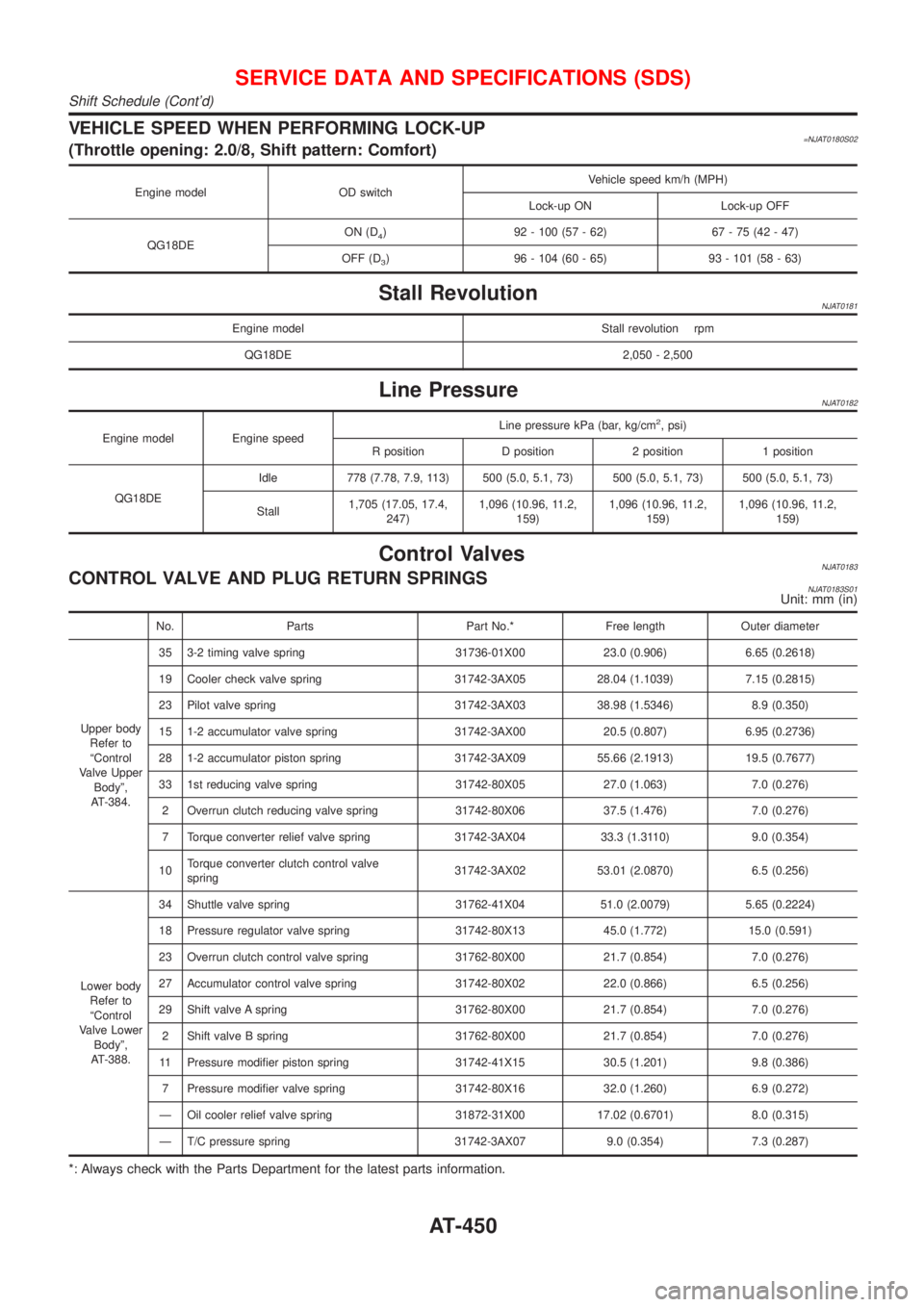
VEHICLE SPEED WHEN PERFORMING LOCK-UP=NJAT0180S02(Throttle opening: 2.0/8, Shift pattern: Comfort)
Engine model OD switchVehicle speed km/h (MPH)
Lock-up ON Lock-up OFF
QG18DEON (D
4) 92 - 100 (57 - 62) 67 - 75 (42 - 47)
OFF (D
3) 96 - 104 (60 - 65) 93 - 101 (58 - 63)
Stall RevolutionNJAT0181
Engine model Stall revolution rpm
QG18DE 2,050 - 2,500
Line PressureNJAT0182
Engine model Engine speedLine pressure kPa (bar, kg/cm
2, psi)
R position D position 2 position 1 position
QG18DEIdle 778 (7.78, 7.9, 113) 500 (5.0, 5.1, 73) 500 (5.0, 5.1, 73) 500 (5.0, 5.1, 73)
Stall1,705 (17.05, 17.4,
247)1,096 (10.96, 11.2,
159)1,096 (10.96, 11.2,
159)1,096 (10.96, 11.2,
159)
Control ValvesNJAT0183CONTROL VALVE AND PLUG RETURN SPRINGSNJAT0183S01Unit: mm (in)
No. Parts Part No.* Free length Outer diameter
Upper body
Refer to
ªControl
Valve Upper
Bodyº,
AT-384.35 3-2 timing valve spring 31736-01X00 23.0 (0.906) 6.65 (0.2618)
19 Cooler check valve spring 31742-3AX05 28.04 (1.1039) 7.15 (0.2815)
23 Pilot valve spring 31742-3AX03 38.98 (1.5346) 8.9 (0.350)
15 1-2 accumulator valve spring 31742-3AX00 20.5 (0.807) 6.95 (0.2736)
28 1-2 accumulator piston spring 31742-3AX09 55.66 (2.1913) 19.5 (0.7677)
33 1st reducing valve spring 31742-80X05 27.0 (1.063) 7.0 (0.276)
2 Overrun clutch reducing valve spring 31742-80X06 37.5 (1.476) 7.0 (0.276)
7 Torque converter relief valve spring 31742-3AX04 33.3 (1.3110) 9.0 (0.354)
10Torque converter clutch control valve
spring31742-3AX02 53.01 (2.0870) 6.5 (0.256)
Lower body
Refer to
ªControl
Valve Lower
Bodyº,
AT-388.34 Shuttle valve spring 31762-41X04 51.0 (2.0079) 5.65 (0.2224)
18 Pressure regulator valve spring 31742-80X13 45.0 (1.772) 15.0 (0.591)
23 Overrun clutch control valve spring 31762-80X00 21.7 (0.854) 7.0 (0.276)
27 Accumulator control valve spring 31742-80X02 22.0 (0.866) 6.5 (0.256)
29 Shift valve A spring 31762-80X00 21.7 (0.854) 7.0 (0.276)
2 Shift valve B spring 31762-80X00 21.7 (0.854) 7.0 (0.276)
11 Pressure modifier piston spring 31742-41X15 30.5 (1.201) 9.8 (0.386)
7 Pressure modifier valve spring 31742-80X16 32.0 (1.260) 6.9 (0.272)
Ð Oil cooler relief valve spring 31872-31X00 17.02 (0.6701) 8.0 (0.315)
Ð T/C pressure spring 31742-3AX07 9.0 (0.354) 7.3 (0.287)
*: Always check with the Parts Department for the latest parts information.
SERVICE DATA AND SPECIFICATIONS (SDS)
Shift Schedule (Cont'd)
AT-450
Page 1638 of 2493

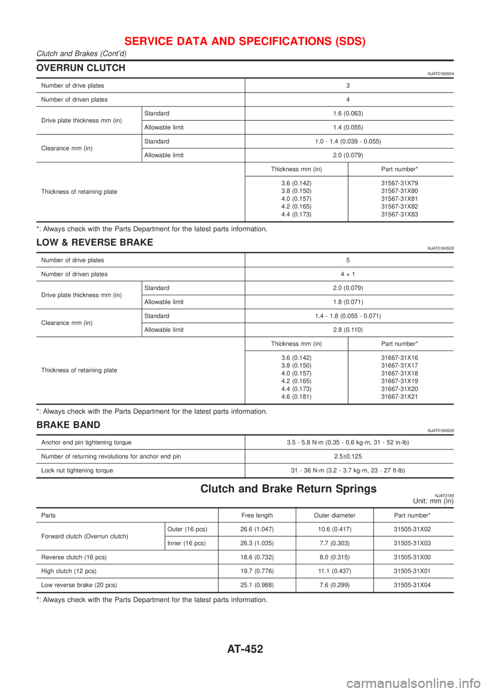
OVERRUN CLUTCHNJAT0184S04
Number of drive plates3
Number of driven plates4
Drive plate thickness mm (in)Standard 1.6 (0.063)
Allowable limit 1.4 (0.055)
Clearance mm (in)Standard 1.0 - 1.4 (0.039 - 0.055)
Allowable limit 2.0 (0.079)
Thickness of retaining plateThickness mm (in) Part number*
3.6 (0.142)
3.8 (0.150)
4.0 (0.157)
4.2 (0.165)
4.4 (0.173)31567-31X79
31567-31X80
31567-31X81
31567-31X82
31567-31X83
*: Always check with the Parts Department for the latest parts information.
LOW & REVERSE BRAKENJAT0184S05
Number of drive plates5
Number of driven plates4+1
Drive plate thickness mm (in)Standard 2.0 (0.079)
Allowable limit 1.8 (0.071)
Clearance mm (in)Standard 1.4 - 1.8 (0.055 - 0.071)
Allowable limit 2.8 (0.110)
Thickness of retaining plateThickness mm (in) Part number*
3.6 (0.142)
3.8 (0.150)
4.0 (0.157)
4.2 (0.165)
4.4 (0.173)
4.6 (0.181)31667-31X16
31667-31X17
31667-31X18
31667-31X19
31667-31X20
31667-31X21
*: Always check with the Parts Department for the latest parts information.
BRAKE BANDNJAT0184S06
Anchor end pin tightening torque 3.5 - 5.8 N´m (0.35 - 0.6 kg-m, 31 - 52 in-lb)
Number of returning revolutions for anchor end pin 2.5±0.125
Lock nut tightening torque 31 - 36 N´m (3.2 - 3.7 kg-m, 23 - 27 ft-lb)
Clutch and Brake Return SpringsNJAT0185Unit: mm (in)
Parts Free length Outer diameter Part number*
Forward clutch (Overrun clutch)Outer (16 pcs) 26.6 (1.047) 10.6 (0.417) 31505-31X02
Inner (16 pcs) 26.3 (1.035) 7.7 (0.303) 31505-31X03
Reverse clutch (16 pcs) 18.6 (0.732) 8.0 (0.315) 31505-31X00
High clutch (12 pcs) 19.7 (0.776) 11.1 (0.437) 31505-31X01
Low reverse brake (20 pcs) 25.1 (0.988) 7.6 (0.299) 31505-31X04
*: Always check with the Parts Department for the latest parts information.
SERVICE DATA AND SPECIFICATIONS (SDS)
Clutch and Brakes (Cont'd)
AT-452
Page 1643 of 2493

Bearing Retainer=NJAT0192SEAL RING CLEARANCENJAT0192S01Unit: mm (in)
Bearing retainer seal ring clearanceStandard 0.10 - 0.25 (0.0039 - 0.0098)
Allowable limit 0.25 (0.0098)
Total End PlayNJAT0193
Total end play ªT3º0.25 - 0.55 mm (0.0098 - 0.0217 in)
BEARING RACE FOR ADJUSTING TOTAL END PLAYNJAT0193S01
Thickness mm (in) Part number*
0.6 (0.024)
0.8 (0.031)
1.0 (0.039)
1.2 (0.047)
1.4 (0.055)
1.6 (0.063)
1.8 (0.071)
2.0 (0.079)31435-31X01
31435-31X02
31435-31X03
31435-31X04
31435-31X05
31435-31X06
31435-31X07
31435-31X08
*: Always check with the Parts Department for the latest parts information.
Reverse Clutch End PlayNJAT0194
Reverse clutch end play ªT4º 0.65 - 1.00 mm (0.0256 - 0.0394 in)
THRUST WASHERS FOR ADJUSTING REVERSE CLUTCH END PLAYNJAT0194S01
Thickness mm (in) Part number*
0.65 (0.0256)
0.80 (0.0315)
0.95 (0.0374)
1.10 (0.0433)
1.25 (0.0492)
1.40 (0.0551)31508-31X10
31508-31X11
31508-31X12
31508-31X13
31508-31X14
31508-31X15
*: Always check with the Parts Department for the latest parts information.
AccumulatorNJAT0195O-RINGNJAT0195S01Unit: mm (in)
Accumulator Diameter (Small) Part number* Diameter (Large) Part number*
Servo release accumulator 26.9 (1.059) 31526-41X03 44.2 (1.740) 31526-41X02
N-D accumulator 34.6 (1.362) 31526-31X08 39.4 (1.551) 31672-21X00
*: Always check with the Parts Department for the latest parts information.
RETURN SPRINGNJAT0195S02Unit: mm (in)
Accumulator Free length Outer diameter Part number*
Servo release accumulator springQG18DE + 3AX10, 3AX18 models 52.5 (2.067) 20.1 (0.791) 31605-80X00
Except QG18DE + 3AX10, 3AX18 mod-
els52.5 (2.067) 20.4 (0.803) 31605-80X03
N-D accumulator spring 45.0 (1.772) 27.6 (1.087) 31605-33X01
*: Always check with the Parts Department for the latest parts information.
SERVICE DATA AND SPECIFICATIONS (SDS)
Bearing Retainer
AT-457
Page 1644 of 2493

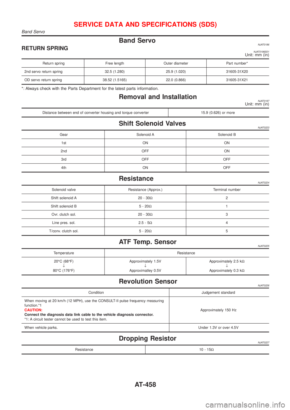
Band ServoNJAT0196RETURN SPRINGNJAT0196S01Unit: mm (in)
Return spring Free length Outer diameter Part number*
2nd servo return spring 32.5 (1.280) 25.9 (1.020) 31605-31X20
OD servo return spring 38.52 (1.5165) 22.0 (0.866) 31605-31X21
*: Always check with the Parts Department for the latest parts information.
Removal and InstallationNJAT0197Unit: mm (in)
Distance between end of converter housing and torque converter 15.9 (0.626) or more
Shift Solenoid ValvesNJAT0223
Gear Solenoid A Solenoid B
1st ON ON
2nd OFF ON
3rd OFF OFF
4th ON OFF
ResistanceNJAT0224
Solenoid valve Resistance (Approx.) Terminal number
Shift solenoid A 20 - 30W2
Shift solenoid B 5 - 20W1
Ovr. clutch sol. 20 - 30W3
Line pres. sol. 2.5 - 5W4
T/conv. clutch sol. 5 - 20W5
ATF Temp. SensorNJAT0225
Temperature Resistance
20ÉC (68ÉF)
¯
80ÉC (176ÉF)Approximately 1.5V
¯
Approximatley 0.5VApproximately 2.5 kW
¯
Approximately 0.3 kW
Revolution SensorNJAT0226
Condition Judgement standard
When moving at 20 km/h (12 MPH), use the CONSULT-II pulse frequency measuring
function.*1
CAUTION:
Connect the diagnosis data link cable to the vehicle diagnosis connector.
*1: A circuit tester cannot be used to test this item.Approximately 150 Hz
When vehicle parks.Under 1.3V or over 4.5V
Dropping ResistorNJAT0227
Resistance 10 - 15W
SERVICE DATA AND SPECIFICATIONS (SDS)
Band Servo
AT-458
Page 1695 of 2493
Torsion Beam, Lateral Link and Control Rod
DISASSEMBLYNJSU0036+Remove torsion beam assembly. Refer to ªRemoval and
Installationº, ªREAR SUSPENSIONº, SU-21.
+Remove lateral link and control rod from torsion beam.
ARA072
INSPECTIONNJSU0037+Check for cracks, distortion or other damage. Replace if nec-
essary.
Standard length:
A 207 - 208 mm (8.15 - 8.19 in)
B 394 - 395 mm (15.51 - 15.55 in)
C 601 - 603 mm (23.66 - 23.74 in)
D 106 - 108 mm (4.17 - 4.25 in)
+Check all rubber parts for wear, cracks or deformation.
Replace if necessary.
SRA793A
ASSEMBLYNJSU00381. Temporarily assemble lateral link and control rod.
+When installing the control rod, connect the bush with the
smaller inner diameter to the lateral link.
SRA701A
2. Temporarily install lateral link and control rod on torsion beam.
+When installing, place lateral link with the arrow topside.
REAR SUSPENSION
Torsion Beam, Lateral Link and Control Rod
SU-23
Page 1731 of 2493

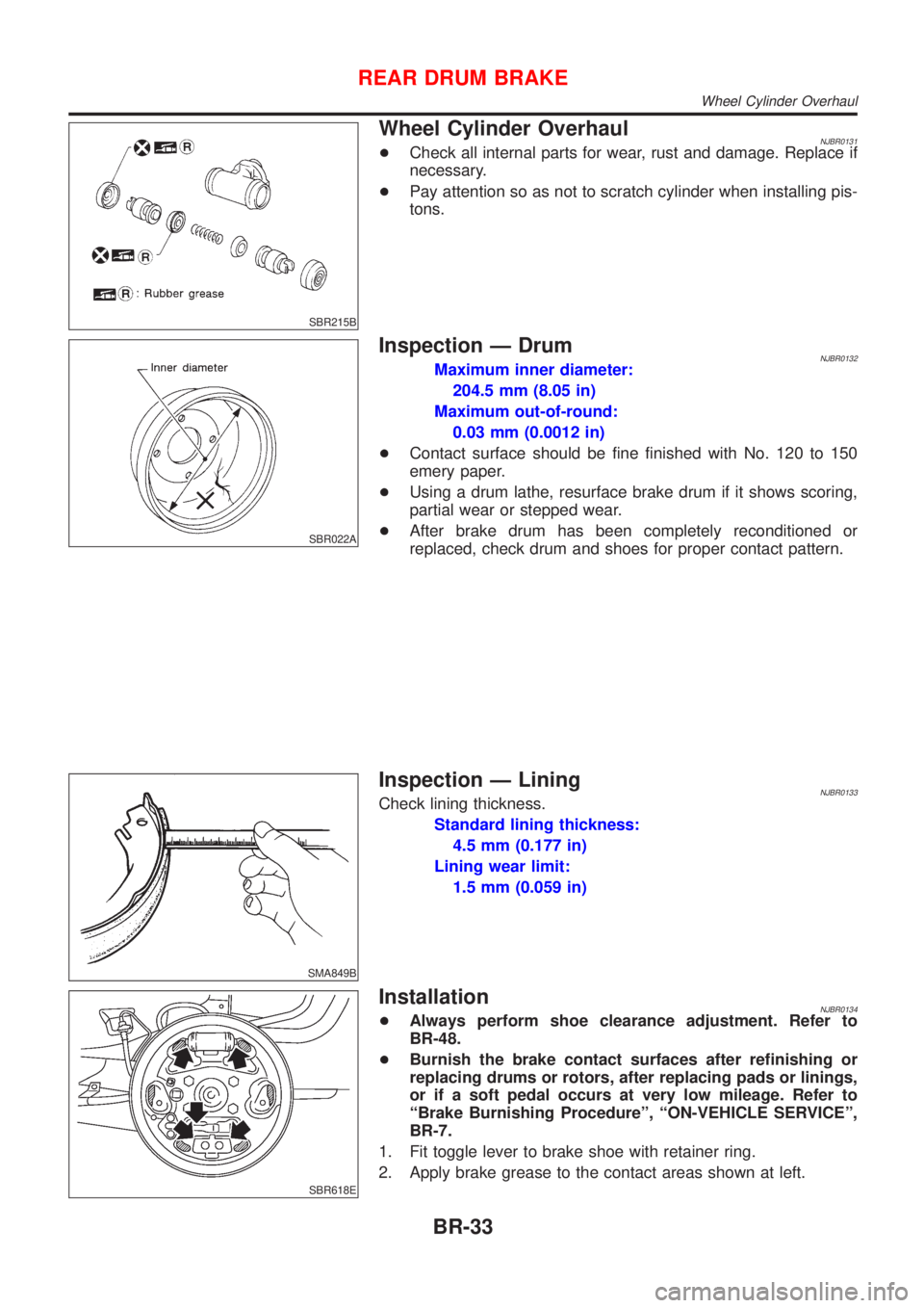
SBR215B
Wheel Cylinder OverhaulNJBR0131+Check all internal parts for wear, rust and damage. Replace if
necessary.
+Pay attention so as not to scratch cylinder when installing pis-
tons.
SBR022A
Inspection Ð DrumNJBR0132Maximum inner diameter:
204.5 mm (8.05 in)
Maximum out-of-round:
0.03 mm (0.0012 in)
+Contact surface should be fine finished with No. 120 to 150
emery paper.
+Using a drum lathe, resurface brake drum if it shows scoring,
partial wear or stepped wear.
+After brake drum has been completely reconditioned or
replaced, check drum and shoes for proper contact pattern.
SMA849B
Inspection Ð LiningNJBR0133Check lining thickness.
Standard lining thickness:
4.5 mm (0.177 in)
Lining wear limit:
1.5 mm (0.059 in)
SBR618E
InstallationNJBR0134+Always perform shoe clearance adjustment. Refer to
BR-48.
+Burnish the brake contact surfaces after refinishing or
replacing drums or rotors, after replacing pads or linings,
or if a soft pedal occurs at very low mileage. Refer to
ªBrake Burnishing Procedureº, ªON-VEHICLE SERVICEº,
BR-7.
1. Fit toggle lever to brake shoe with retainer ring.
2. Apply brake grease to the contact areas shown at left.
REAR DRUM BRAKE
Wheel Cylinder Overhaul
BR-33