Page 978 of 2493

6 CHECK GLOW INDICATOR LAMP POWER SUPPLY CIRCUIT
1. Turn ignition switch ªOFFº.
2. Disconnect combination meter harness connector M32 or M152 or M171.
3. Turn ignition switch ªONº.
4. Check voltage between combination meter terminal 40 or 17 or 1 and ground with CONSULT-II or tester.
YEC060A
OK or NG
OK©GO TO 8.
NG©GO TO 7.
7 DETECT MALFUNCTIONING PART
Check the following.
1. Fuse block (J/B) connector M1
2. 10A fuse
3. Harness for open or short between combination meter and fuse
©Repair open circuit or short to ground or short to power in harness or connectors.
8 CHECK GLOW INDICATOR LAMP OUTPUT SIGNAL CIRCUIT FOR OPEN AND SHORT
1. Turn ignition switch ªOFFº.
2. Disconnect ECM harness connector.
3. Disconnect combination meter harness connector M171.
4. Check harness continuity between ECM terminal 508 and combination meter terminal 17. Refer to Wiring Diagram.
Continuity should exist.
5. Also check harness for short to ground and short to power.
OK or NG
OK©GO TO 10.
NG©GO TO 9.
9 DETECT MALFUNCTIONING PART
Check the following.
1. Harness connectors M63, F102
2. Harness for open or short between combination meter and ECM
©Repair open circuit or short to ground or short to power in harness or connectors.
10 CHECK COMBINATION METER
Check combination meter and glow indicator lamp. Refer to EL-89, ªMeter and Gaugesº.
OK or NG
OK©GO TO 18.
NG©Repair or replace combination meter or glow indicator lamp.
GLOW CONTROL SYSTEMYD
Diagnostic Procedure (Cont'd)
EC-682
Page 1035 of 2493
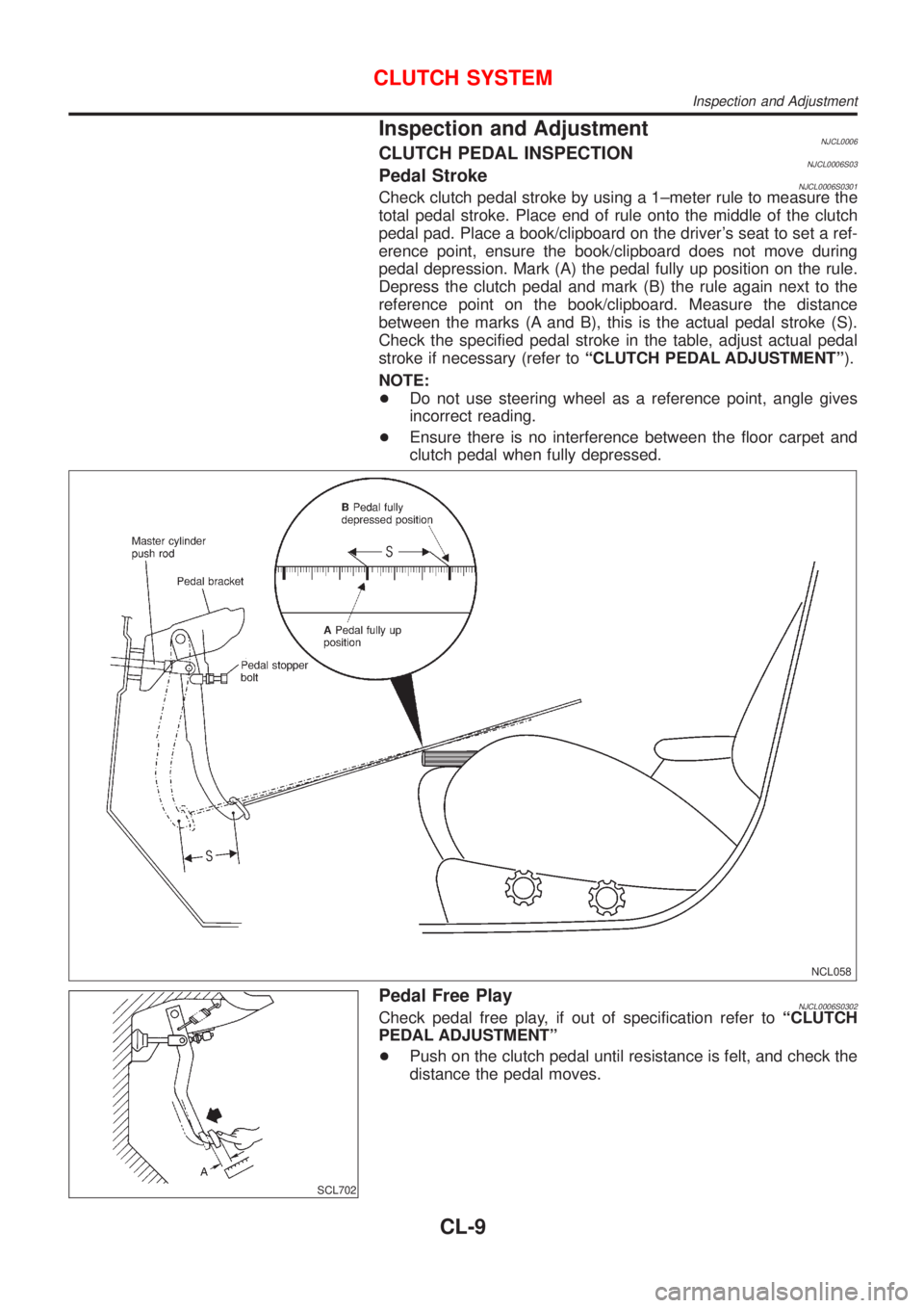
Inspection and AdjustmentNJCL0006CLUTCH PEDAL INSPECTIONNJCL0006S03Pedal StrokeNJCL0006S0301Check clutch pedal stroke by using a 1±meter rule to measure the
total pedal stroke. Place end of rule onto the middle of the clutch
pedal pad. Place a book/clipboard on the driver's seat to set a ref-
erence point, ensure the book/clipboard does not move during
pedal depression. Mark (A) the pedal fully up position on the rule.
Depress the clutch pedal and mark (B) the rule again next to the
reference point on the book/clipboard. Measure the distance
between the marks (A and B), this is the actual pedal stroke (S).
Check the specified pedal stroke in the table, adjust actual pedal
stroke if necessary (refer toªCLUTCH PEDAL ADJUSTMENTº).
NOTE:
+Do not use steering wheel as a reference point, angle gives
incorrect reading.
+Ensure there is no interference between the floor carpet and
clutch pedal when fully depressed.
NCL058
SCL702
Pedal Free PlayNJCL0006S0302Check pedal free play, if out of specification refer toªCLUTCH
PEDAL ADJUSTMENTº
+Push on the clutch pedal until resistance is felt, and check the
distance the pedal moves.
CLUTCH SYSTEM
Inspection and Adjustment
CL-9
Page 1050 of 2493
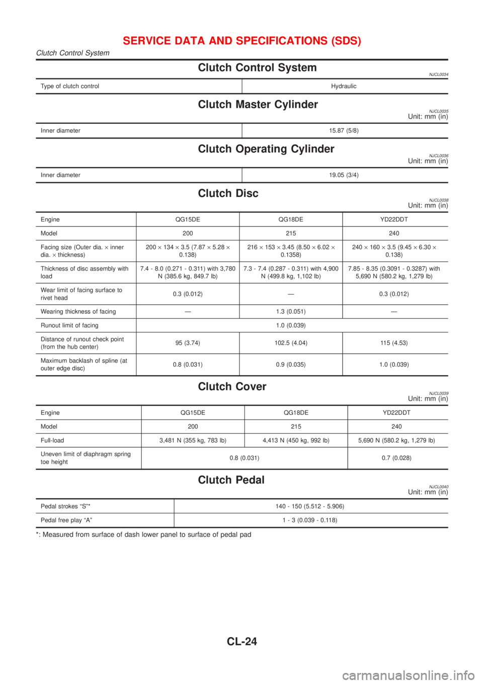
Clutch Control SystemNJCL0034
Type of clutch controlHydraulic
Clutch Master CylinderNJCL0035Unit: mm (in)
Inner diameter15.87 (5/8)
Clutch Operating CylinderNJCL0036Unit: mm (in)
Inner diameter19.05 (3/4)
Clutch DiscNJCL0038Unit: mm (in)
Engine QG15DE QG18DE YD22DDT
Model 200 215 240
Facing size (Outer dia.´inner
dia.´thickness)200´134´3.5 (7.87´5.28´
0.138)216´153´3.45 (8.50´6.02´
0.1358)240´160´3.5 (9.45´6.30´
0.138)
Thickness of disc assembly with
load7.4 - 8.0 (0.271 - 0.311) with 3,780
N (385.6 kg, 849.7 lb)7.3 - 7.4 (0.287 - 0.311) with 4,900
N (499.8 kg, 1,102 lb)7.85 - 8.35 (0.3091 - 0.3287) with
5,690 N (580.2 kg, 1,279 lb)
Wear limit of facing surface to
rivet head0.3 (0.012) Ð 0.3 (0.012)
Wearing thickness of facing Ð 1.3 (0.051) Ð
Runout limit of facing 1.0 (0.039)
Distance of runout check point
(from the hub center)95 (3.74) 102.5 (4.04) 115 (4.53)
Maximum backlash of spline (at
outer edge disc)0.8 (0.031) 0.9 (0.035) 1.0 (0.039)
Clutch CoverNJCL0039Unit: mm (in)
Engine QG15DE QG18DE YD22DDT
Model 200 215 240
Full-load 3,481 N (355 kg, 783 lb) 4,413 N (450 kg, 992 lb) 5,690 N (580.2 kg, 1,279 lb)
Uneven limit of diaphragm spring
toe height0.8 (0.031) 0.7 (0.028)
Clutch PedalNJCL0040Unit: mm (in)
Pedal strokes ªSº* 140 - 150 (5.512 - 5.906)
Pedal free play ªAº1 - 3 (0.039 - 0.118)
*: Measured from surface of dash lower panel to surface of pedal pad
SERVICE DATA AND SPECIFICATIONS (SDS)
Clutch Control System
CL-24
Page 1073 of 2493
NJMT0008
SMT928D
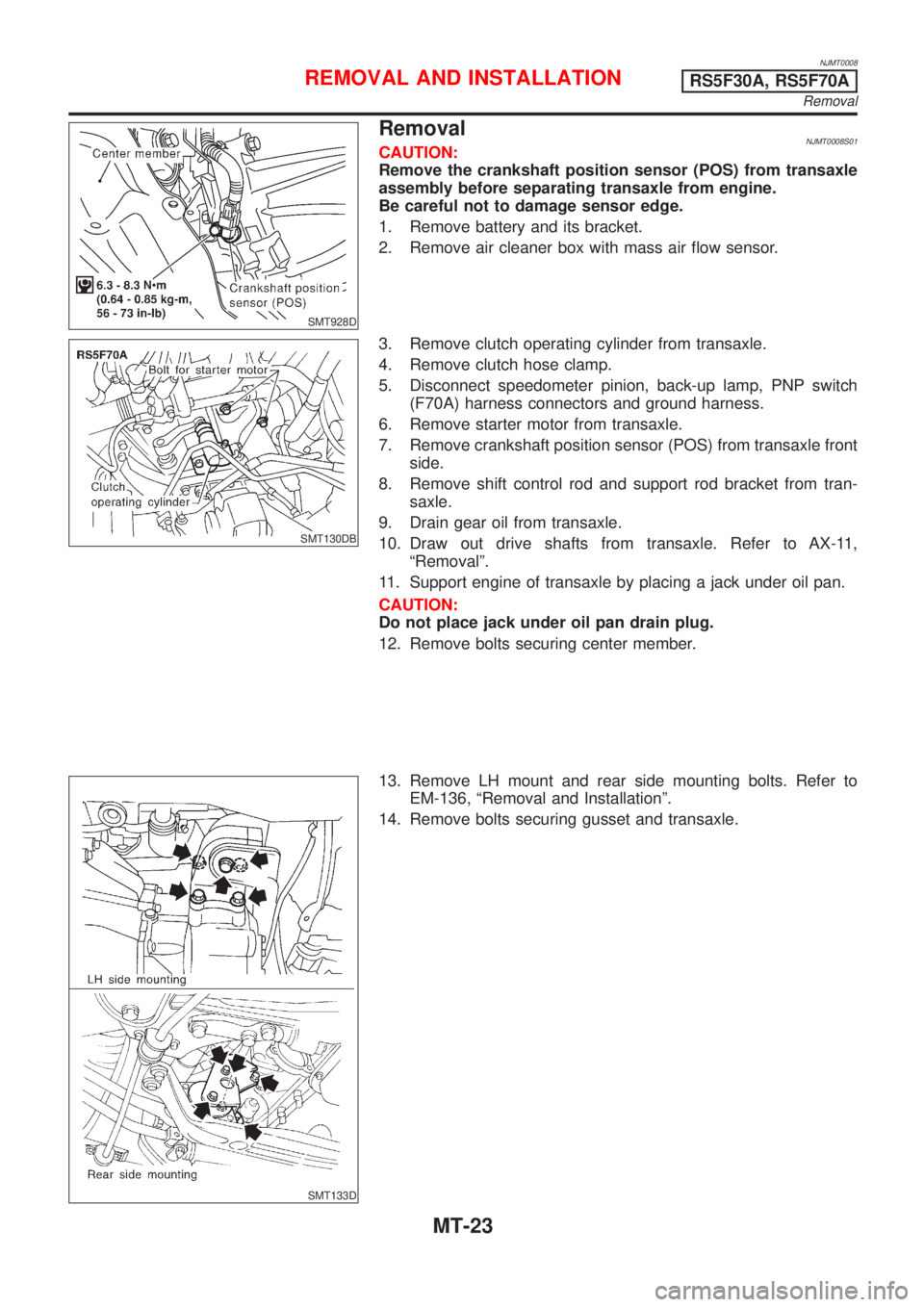
RemovalNJMT0008S01CAUTION:
Remove the crankshaft position sensor (POS) from transaxle
assembly before separating transaxle from engine.
Be careful not to damage sensor edge.
1. Remove battery and its bracket.
2. Remove air cleaner box with mass air flow sensor.
SMT130DB
3. Remove clutch operating cylinder from transaxle.
4. Remove clutch hose clamp.
5. Disconnect speedometer pinion, back-up lamp, PNP switch
(F70A) harness connectors and ground harness.
6. Remove starter motor from transaxle.
7. Remove crankshaft position sensor (POS) from transaxle front
side.
8. Remove shift control rod and support rod bracket from tran-
saxle.
9. Drain gear oil from transaxle.
10. Draw out drive shafts from transaxle. Refer to AX-11,
ªRemovalº.
11. Support engine of transaxle by placing a jack under oil pan.
CAUTION:
Do not place jack under oil pan drain plug.
12. Remove bolts securing center member.
SMT133D
13. Remove LH mount and rear side mounting bolts. Refer to
EM-136, ªRemoval and Installationº.
14. Remove bolts securing gusset and transaxle.
REMOVAL AND INSTALLATIONRS5F30A, RS5F70A
Removal
MT-23
Page 1076 of 2493
NJMT0090
SMT928D
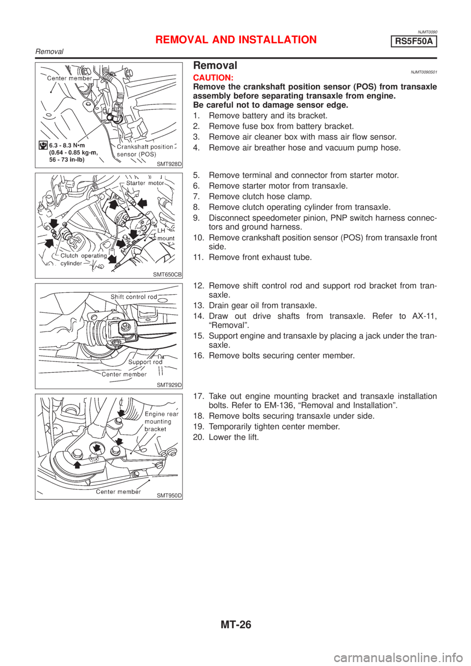
RemovalNJMT0090S01CAUTION:
Remove the crankshaft position sensor (POS) from transaxle
assembly before separating transaxle from engine.
Be careful not to damage sensor edge.
1. Remove battery and its bracket.
2. Remove fuse box from battery bracket.
3. Remove air cleaner box with mass air flow sensor.
4. Remove air breather hose and vacuum pump hose.
SMT650CB
5. Remove terminal and connector from starter motor.
6. Remove starter motor from transaxle.
7. Remove clutch hose clamp.
8. Remove clutch operating cylinder from transaxle.
9. Disconnect speedometer pinion, PNP switch harness connec-
tors and ground harness.
10. Remove crankshaft position sensor (POS) from transaxle front
side.
11. Remove front exhaust tube.
SMT929D
12. Remove shift control rod and support rod bracket from tran-
saxle.
13. Drain gear oil from transaxle.
14. Draw out drive shafts from transaxle. Refer to AX-11,
ªRemovalº.
15. Support engine and transaxle by placing a jack under the tran-
saxle.
16. Remove bolts securing center member.
SMT950D
17. Take out engine mounting bracket and transaxle installation
bolts. Refer to EM-136, ªRemoval and Installationº.
18. Remove bolts securing transaxle under side.
19. Temporarily tighten center member.
20. Lower the lift.
REMOVAL AND INSTALLATIONRS5F50A
Removal
MT-26
Page 1080 of 2493
NJMT0039
Case ComponentsNJMT0039S01
SMT956DA
1. Clutch housing
2. Input shaft oil seal
3. Oil pocket
4. Bearing retainer
5. Torx screw
6. Filler plug
7. Air breather tube
8. Welch plug
9. O-ring10. Case cover
11. Back-up lamp switch
12. Differential oil seal
13. Drain plug
14. Transmission case
15. Oil gutter
16. Reverse idler shaft
17. Oil channel
18. Striking rod oil seal19. Boot
20. Differential oil seal
21. O-ring
22. Speedometer pinion assembly
23. Magnet
24. Earth term
25. Welch plug
26. Welch plug
27. PNP switch
OVERHAULRS5F30A
Case Components
MT-30
Page 1081 of 2493
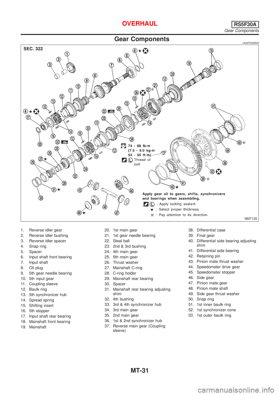
Gear Components=NJMT0039S02
NMT135
1. Reverse idler gear
2. Reverse idler bushing
3. Reverse idler spacer
4. Snap ring
5. Spacer
6. Input shaft front bearing
7. Input shaft
8. Oil plug
9. 5th gear needle bearing
10. 5th input gear
11. Coupling sleeve
12. Baulk ring
13. 5th synchronizer hub
14. Spread spring
15. Shifting insert
16. 5th stopper
17. Input shaft rear bearing
18. Mainshaft front bearing
19. Mainshaft20. 1st main gear
21. 1st gear needle bearing
22. Steel ball
23. 2nd & 3rd bushing
24. 4th main gear
25. 5th main gear
26. Thrust washer
27. Mainshaft C-ring
28. C-ring holder
29. Mainshaft rear bearing
30. Spacer
31. Mainshaft rear bearing adjusting
shim
32. 4th bushing
33. 3rd & 4th synchronizer hub
34. 3rd main gear
35. 2nd main gear
36. 1st & 2nd synchronizer hub
37. Reverse main gear (Coupling
sleeve)38. Differential case
39. Final gear
40. Differential side bearing adjusting
shim
41. Differential side bearing
42. Retaining pin
43. Pinion mate thrust washer
44. Speedometer drive gear
45. Speedometer stopper
46. Side gear
47. Pinion mate gear
48. Pinion mate shaft
49. Side gear thrust washer
50. Snap ring
51. 1st inner baulk ring
52. 1st synchronizer cone
53. 1st outer baulk ring
OVERHAULRS5F30A
Gear Components
MT-31
Page 1093 of 2493
SMT606AA
6. Press on 5th main gear.
SMT592-A
7. Install thrust washer.
8. Select and install mainshaft C-ring that gives proper clearance
of groove in mainshaft.
Allowable clearance of groove:
0 - 0.1 mm (0 - 0.004 in)
Mainshaft C-ring:
Refer to SDS, MT-121.
9. Install C-ring holder.
SMT607AA
10. Press on mainshaft rear bearing.
SMT639
11. Press on mainshaft front bearing.
12. Measure gear end play as the final check Ð Refer to
ªDISASSEMBLYº, MT-39.
SMT647-A
Final Drive
DISASSEMBLYNJMT00481. Remove final gear.
2. Remove speedometer drive gear by cutting it.
3. Press out differential side bearings.
+Be careful not to mix up the right and left bearings.
REPAIR FOR COMPONENT PARTSRS5F30A
Mainshaft and Gears (Cont'd)
MT-43