2001 NISSAN ALMERA N16 ESP
[x] Cancel search: ESPPage 6 of 2493

The security indicator is located on the combi meter. The indicator
blinks when the ignition switch is in ªOFFº or ªACCº position.
Therefore, NATS warns outsiders that the vehicle is equipped with
the anti-theft system.
+When NATS detects trouble, the security indicator lamp lights
up while ignition switch is in ªONº position.
This lighting up indicates that the anti-theft is not functioning,
so prompt service is required.
+When servicing NATS (trouble diagnoses, system initialization
and additional registration of other NATS ignition key IDs),
CONSULT-II hardware and CONSULT-II NATS software is
necessary.
Regarding the procedures of NATS initialization and NATS
ignition key ID registration, refer to CONSULT-II operation
manual, NATS.
Therefore, CONSULT-II NATS software (program card and
operation manual) must be kept strictly confidential to main-
tain the integrity of the anti-theft function.
+When servicing NATS (trouble diagnoses, system initialization
and additional registration of other NATS ignition key IDs), it
may be necessary to re-register original key identification.
Therefore, be sure to receive all keys from vehicle owner. A
maximum of five key IDs can be registered into NATS.
+When failing to start the engine first time using the key of
NATS, start as follows.
a) Leave the ignition key in ªONº position for approximately 5
seconds.
b) Turn ignition key to ªOFFº or ªLOCKº position and wait approxi-
mately 5 seconds.
c) Repeat step 1 and 2 again.
d) Restart the engine while keeping the key separate from any
others on key-chain.
SGI285
GENERAL PRECAUTIONSNJGI0001S03+Do not operate the engine for an extended period of time
without proper exhaust ventilation.
Keep the work area well ventilated and free of any inflammable
materials. Special care should be taken when handling any
inflammable or poisonous materials, such as gasoline, refrig-
erant gas, etc. When working in a pit or other enclosed area,
be sure to properly ventilate the area before working with haz-
ardous materials.
Do not smoke while working on the vehicle.
SGI231
+Before jacking up the vehicle, apply wheel chocks or other tire
blocks to the wheels to prevent the vehicle from moving. After
jacking up the vehicle, support the vehicle weight with safety
stands at the points designated for proper lifting before work-
ing on the vehicle.
These operations should be done on a level surface.
+When removing a heavy component such as the engine or
transaxle, be careful not to lose your balance and drop them.
Also, do not allow them to strike adjacent parts, especially the
brake tubes and master cylinder.
PRECAUTIONS
Precautions (Cont'd)
GI-4
Page 16 of 2493

Description=NJGI0003S02
Number Item Description
1 Power condition+This shows the condition when the system receives battery positive voltage (can be
operated).
2 Fusible link+The double line shows that this is a fusible link.
+The open circle shows current flow in, and the shaded circle shows current flow out.
3Fusible link/fuse loca-
tion+This shows the location of the fusible link or fuse in the fusible link or fuse box. For
arrangement, refer to EL-10, ªPOWER SUPPLY ROUTINGº.
4 Fuse+The single line shows that this is a fuse.
+The open circle shows current flow in, and the shaded circle shows current flow out.
5 Current rating+This shows the current rating of the fusible link or fuse.
6 Connectors+This shows that connector E3 is female and connector M1 is male.
+The G/R wire is located in the 1A terminal of both connectors.
+Terminal number with an alphabet (1A, 5B, etc.) indicates that the connector is SMJ con-
nector. Refer to GI-19.
7 Optional splice+The open circle shows that the splice is optional depending on vehicle application.
8 Splice+The shaded circle shows that the splice is always on the vehicle.
9 Page crossing+This arrow shows that the circuit continues to an adjacent page.
+The A will match with the A on the preceding or next page.
10 Common connector+The dotted lines between terminals show that these terminals are part of the same con-
nector.
11 Option abbreviation+This shows that the circuit is optional depending on vehicle application.
12 Relay+This shows an internal representation of the relay. For details, refer to EL-7, ªSTAN-
DARDIZED RELAYº.
13 Connectors+This shows that the connector is connected to the body or a terminal with bolt or nut.
14 Wire color+This shows a code for the color of the wire.
B = Black
W = White
R = Red
G = Green
L = Blue
Y = Yellow
LG = Light GreenBR = Brown
OR = Orange
P = Pink
PU = Purple
GY = Gray
SB = Sky Blue
CH = Dark Brown
DG = Dark Green
When the wire color is striped, the base color is given first, followed by the stripe color as
shown below:
Example: L/W = Blue with White Stripe
15 Option description+This shows a description of the option abbreviation used on the page.
16 Switch+This shows that continuity exists between terminals 1 and 2 when the switch is in the A
position. Continuity exists between terminals 1 and 3 when the switch is in the B posi-
tion.
17 Assembly parts+Connector terminal in component shows that it is a harness incorporated assembly.
18 Cell code+This identifies each page of the wiring diagram by section, system and wiring diagram
page number.
19 Current flow arrow+Arrow indicates electric current flow, especially where the direction of standard flow (ver-
tically downward or horizontally from left to right) is difficult to follow.
+A double arrow ª
º shows that current can flow in either direction depending on cir-
cuit operation.
HOW TO READ WIRING DIAGRAMS
Description
GI-14
Page 18 of 2493

SGI364
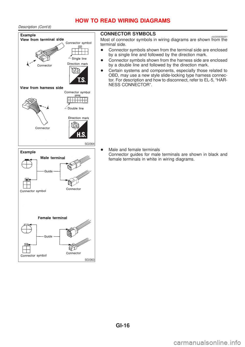
CONNECTOR SYMBOLS=NJGI0003S0201Most of connector symbols in wiring diagrams are shown from the
terminal side.
+Connector symbols shown from the terminal side are enclosed
by a single line and followed by the direction mark.
+Connector symbols shown from the harness side are enclosed
by a double line and followed by the direction mark.
+Certain systems and components, especially those related to
OBD, may use a new style slide-locking type harness connec-
tor. For description and how to disconnect, refer to EL-5, ªHAR-
NESS CONNECTORº.
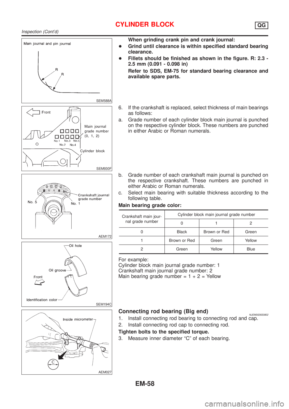
SGI363
+Male and female terminals
Connector guides for male terminals are shown in black and
female terminals in white in wiring diagrams.
HOW TO READ WIRING DIAGRAMS
Description (Cont'd)
GI-16
Page 136 of 2493

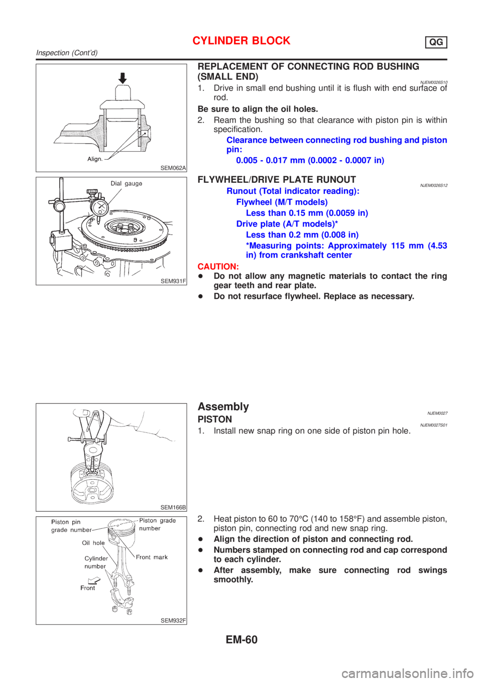
SEM588A
When grinding crank pin and crank journal:
+Grind until clearance is within specified standard bearing
clearance.
+Fillets should be finished as shown in the figure. R: 2.3 -
2.5 mm (0.091 - 0.098 in)
Refer to SDS, EM-75 for standard bearing clearance and
available spare parts.
SEM930F
6. If the crankshaft is replaced, select thickness of main bearings
as follows:
a. Grade number of each cylinder block main journal is punched
on the respective cylinder block. These numbers are punched
in either Arabic or Roman numerals.
AEM172
SEM194C
b. Grade number of each crankshaft main journal is punched on
the respective crankshaft. These numbers are punched in
either Arabic or Roman numerals.
c. Select main bearing with suitable thickness according to the
following table.
Main bearing grade color:
Crankshaft main jour-
nal grade numberCylinder block main journal grade number
012
0 Black Brown or Red Green
1 Brown or Red Green Yellow
2 Green Yellow Blue
For example:
Cylinder block main journal grade number: 1
Crankshaft main journal grade number: 2
Main bearing grade number=1+2=Yellow
AEM027
Connecting rod bearing (Big end)NJEM0026S08021. Install connecting rod bearing to connecting rod and cap.
2. Install connecting rod cap to connecting rod.
Tighten bolts to the specified torque.
3. Measure inner diameter ªCº of each bearing.
CYLINDER BLOCKQG
Inspection (Cont'd)
EM-58
Page 138 of 2493

SEM062A
REPLACEMENT OF CONNECTING ROD BUSHING
(SMALL END)
NJEM0026S101. Drive in small end bushing until it is flush with end surface of
rod.
Be sure to align the oil holes.
2. Ream the bushing so that clearance with piston pin is within
specification.
Clearance between connecting rod bushing and piston
pin:
0.005 - 0.017 mm (0.0002 - 0.0007 in)
SEM931F
FLYWHEEL/DRIVE PLATE RUNOUTNJEM0026S12Runout (Total indicator reading):
Flywheel (M/T models)
Less than 0.15 mm (0.0059 in)
Drive plate (A/T models)*
Less than 0.2 mm (0.008 in)
*Measuring points: Approximately 115 mm (4.53
in) from crankshaft center
CAUTION:
+Do not allow any magnetic materials to contact the ring
gear teeth and rear plate.
+Do not resurface flywheel. Replace as necessary.
SEM166B
AssemblyNJEM0027PISTONNJEM0027S011. Install new snap ring on one side of piston pin hole.
SEM932F
2. Heat piston to 60 to 70ÉC (140 to 158ÉF) and assemble piston,
piston pin, connecting rod and new snap ring.
+Align the direction of piston and connecting rod.
+Numbers stamped on connecting rod and cap correspond
to each cylinder.
+After assembly, make sure connecting rod swings
smoothly.
CYLINDER BLOCKQG
Inspection (Cont'd)
EM-60
Page 140 of 2493

SEM933F
3. Install crankshaft and main bearing caps and tighten bolts to
the specified torque.
+Apply new engine oil to the bolt thread and seat surface.
+Prior to tightening bearing cap bolts, shift crankshaft back
and forth to properly seat the bearing caps.
+Tighten bearing cap bolts gradually in two or three stages.
Start with center bearing and move outward as shown in
figure.
+After securing bearing cap bolts, make sure crankshaft
turns smoothly by hand.
SEM116F
4. Measure crankshaft end play.
Crankshaft end play:
Standard
0.060 - 0.260 mm (0.0024 - 0.0102 in)
Limit
0.3 mm (0.012 in)
If beyond the limit, replace thrust bearing with new ones.
SEM168D
5. Install connecting rod bearings in connecting rods and con-
necting rod caps.
+Confirm that correct bearings are used. Refer to EM-58.
+Install bearings so that oil hole in connecting rod aligns
with oil hole of bearing.
+Apply new engine oil to bolt threads and bearing surfaces.
SEM942F
6. Install pistons with connecting rods.
a. Install them into corresponding cylinders with Tool.
+Make sure connecting rod does not scratch cylinder wall.
+Make sure connecting rod bolts do not scratch crankshaft
pin journals.
+Arrange so that front mark on piston head faces engine.
+Apply new engine oil to piston rings and sliding surface
of piston.
SEM943F
b. Install connecting rod caps.
Apply new engine oil to bolt threads and nut seating surfaces.
Tighten connecting rod cap nuts in the following procedure:
+Tighten to 13.72 to 15.68 N´m (1.399 to 1.599 kg-m, 10.120
to 11.566 ft-lb).
+Turn nuts to 35É to 40É degrees clockwise with an angle
wrench. If an angle wrench is not available, tighten nuts to
23 to 28 N´m (2.3 to 2.9 kg-m, 17 to 21 ft-lb).
CYLINDER BLOCKQG
Assembly (Cont'd)
EM-62
Page 214 of 2493

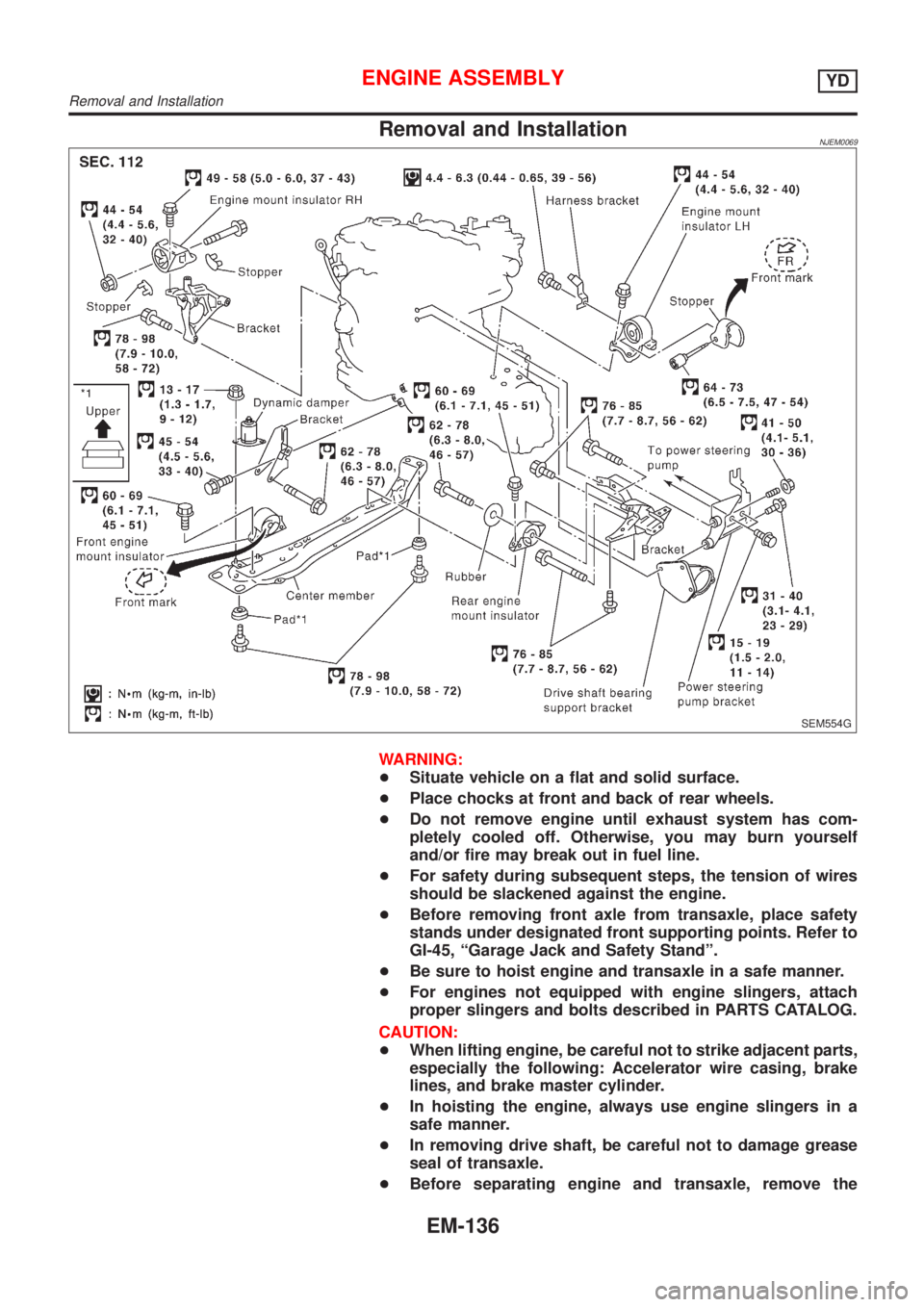
Removal and InstallationNJEM0069
SEM554G
WARNING:
+Situate vehicle on a flat and solid surface.
+Place chocks at front and back of rear wheels.
+Do not remove engine until exhaust system has com-
pletely cooled off. Otherwise, you may burn yourself
and/or fire may break out in fuel line.
+For safety during subsequent steps, the tension of wires
should be slackened against the engine.
+Before removing front axle from transaxle, place safety
stands under designated front supporting points. Refer to
GI-45, ªGarage Jack and Safety Standº.
+Be sure to hoist engine and transaxle in a safe manner.
+For engines not equipped with engine slingers, attach
proper slingers and bolts described in PARTS CATALOG.
CAUTION:
+When lifting engine, be careful not to strike adjacent parts,
especially the following: Accelerator wire casing, brake
lines, and brake master cylinder.
+In hoisting the engine, always use engine slingers in a
safe manner.
+In removing drive shaft, be careful not to damage grease
seal of transaxle.
+Before separating engine and transaxle, remove the
ENGINE ASSEMBLYYD
Removal and Installation
EM-136
Page 218 of 2493

Removal and InstallationNJEM0071CAUTION:
+When installing bearings, pistons, or other sliding parts,
lubricate contacting surfaces with new engine oil.
+Place removed parts such as bearings and bearing caps
in their proper order and direction.
+When installing connecting rod nuts, and main bearing
cap bolts, apply new engine oil to threads and seating
surfaces.
+Do not allow any magnetic materials to contact the signal
plate of flywheel.
+Do not remove the signal plate at back.
+Do not place the signal plate side facing under.
+Handle with care so as not to damage the signal plate
[especially four places on protrusions for signal of crank
position sensor (TDC sensor)].
DisassemblyNJEM0072PISTON AND CRANKSHAFTNJEM0072S011. Remove engine. Refer to ªENGINE ASSEMBLYº, ªRemoval
and Installationº, EM-136.
2. Place engine on a work stand.
a. Remove flywheel.
+Hold ring gear with ring gear stopper (KV10105630,
KV10105610). Then, loosen securing bolts with TORX socket
(size: Q8 E20, Commercial Service Tool) and remove them.
As an alternative method, hold the crankshaft pulley with a
pulley holder (SST) to remove the flywheel.
JEM192G
b. Install engine sub-attachment (SST) to rear surface of cylinder
block.
+To install, align the hole on the sub-attachment with the knock
pin on the cylinder block.
+The engine sub-attachment has five bolts.
c. Install engine attachment (SST).
+The four sets of bolts and nuts are multi-purpose products.
CYLINDER BLOCKYD
Removal and Installation
EM-140